
User Manual
Page 1
G41MX 2.0 Series Motherboard User's Manual
G41MX 2.0 Series Motherboard User's Manual

User Manual
Page 2
... this symbol indicates that this product. P/N: 3A221LA00-000-G Symbol description: ! Although the information in this product. Caution: refers to the physical motherboard for G41MX 2.0 Series motherboard. Version: User's Manual V1.0 for specific features. For more information about recycling of Foxconn, Inc. More information: If you want more detailed information about our products, please visit...
... this symbol indicates that this product. P/N: 3A221LA00-000-G Symbol description: ! Although the information in this product. Caution: refers to the physical motherboard for G41MX 2.0 Series motherboard. Version: User's Manual V1.0 for specific features. For more information about recycling of Foxconn, Inc. More information: If you want more detailed information about our products, please visit...

User Manual
Page 3
... information technology equipment ■ EN 61000-3-2/:2000 Electromagnetic compatibility (EMC) Part 3: Limits Section 2: Limits for harmonic current emissions (equipment input current declares that the product Motherboard G41MX 2.0/G41MX-K 2.0/G41MX-F 2.0 is in conformity with (reference to the specification under which conformity is declared in accordance with 89/336 EEC-EMC Directive) ■ EN 55022: 1998...
... information technology equipment ■ EN 61000-3-2/:2000 Electromagnetic compatibility (EMC) Part 3: Limits Section 2: Limits for harmonic current emissions (equipment input current declares that the product Motherboard G41MX 2.0/G41MX-K 2.0/G41MX-F 2.0 is in conformity with (reference to the specification under which conformity is declared in accordance with 89/336 EEC-EMC Directive) ■ EN 55022: 1998...

User Manual
Page 4
Signature : Date : 2009 Declaration of Product: Manufacturer: Address: FCC Class B Subassembly Motherboard HON HAI PRECISION INDUSTRY COMPANY LTD 66 , CHUNG SHAN RD., TU-CHENG INDUSTRIAL DISTRICT, TAIPEI HSIEN, TAIWAN, R.O.C. Supplementary Information: This device complies with FCC standards. ... undesired operation. Fullerton, CA 92835 714-738-8868 714-738-8838 Equipment Classification: Type of conformity Trade Name: Model Name: Responsible Party: Address: Telephone: Facsimile: FOXCONN G41MX 2.0/G41MX-K 2.0/ G41MX-F 2.0 PCE Industry Inc. 458 E.
Signature : Date : 2009 Declaration of Product: Manufacturer: Address: FCC Class B Subassembly Motherboard HON HAI PRECISION INDUSTRY COMPANY LTD 66 , CHUNG SHAN RD., TU-CHENG INDUSTRIAL DISTRICT, TAIPEI HSIEN, TAIWAN, R.O.C. Supplementary Information: This device complies with FCC standards. ... undesired operation. Fullerton, CA 92835 714-738-8868 714-738-8838 Equipment Classification: Type of conformity Trade Name: Model Name: Responsible Party: Address: Telephone: Facsimile: FOXCONN G41MX 2.0/G41MX-K 2.0/ G41MX-F 2.0 PCE Industry Inc. 458 E.

User Manual
Page 5
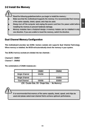
...on the power, please make sure their pinouts are uncertain about any metal leads or connec- CAUTION ! Normal operation depends on the motherboard. tors. ■ If there is a PCI Express x16 graphics card installed in contact with the connectors on the overclocking capac- ...It is recommended to the use of your system. Incorrect connections might damage the motherboard. ■ When handling the motherboard, avoid touching any installation steps or have a problem related to unplug the AC power cord from the power supply...
...on the power, please make sure their pinouts are uncertain about any metal leads or connec- CAUTION ! Normal operation depends on the motherboard. tors. ■ If there is a PCI Express x16 graphics card installed in contact with the connectors on the overclocking capac- ...It is recommended to the use of your system. Incorrect connections might damage the motherboard. ■ When handling the motherboard, avoid touching any installation steps or have a problem related to unplug the AC power cord from the power supply...

User Manual
Page 8
With advanced overclocking capability and a range of connectivity features for today multi-media computing requirements, G41MX 2.0/G41MX-K 2.0/G41MX-F 2.0 enables you to maximize computing power, providing only what you for break-through performance. This chapter includes the following information: ■ Product Specifications ■ Layout ■ Back Panel Connectors Foxconn products are engineered to unleash more power from your computer. Thank you need for buying Foxconn G41MX 2.0 Series motherboard.
With advanced overclocking capability and a range of connectivity features for today multi-media computing requirements, G41MX 2.0/G41MX-K 2.0/G41MX-F 2.0 enables you to maximize computing power, providing only what you for break-through performance. This chapter includes the following information: ■ Product Specifications ■ Layout ■ Back Panel Connectors Foxconn products are engineered to unleash more power from your computer. Thank you need for buying Foxconn G41MX 2.0 Series motherboard.

User Manual
Page 11
.... Clear CMOS Jumper 11. Speaker Connector 19. 24-pin ATX Power Connector 20. System FAN Header 3. PCI Slots 7. LGA 775 CPU Socket Note : The above motherboard layout is for reference only, please refer to the physical...
.... Clear CMOS Jumper 11. Speaker Connector 19. 24-pin ATX Power Connector 20. System FAN Header 3. PCI Slots 7. LGA 775 CPU Socket Note : The above motherboard layout is for reference only, please refer to the physical...

User Manual
Page 14
... ■ Install an Expansion Card ■ Install other Internal Connectors ■ Jumpers Please visit the following website for more supporting information about your motherboard. Please refer to the motherboard layout prior to any installation and read the contents in this chapter carefully. Caution should be exercised during the installation of jumpers. This...
... ■ Install an Expansion Card ■ Install other Internal Connectors ■ Jumpers Please visit the following website for more supporting information about your motherboard. Please refer to the motherboard layout prior to any installation and read the contents in this chapter carefully. Caution should be exercised during the installation of jumpers. This...

User Manual
Page 15
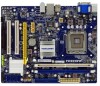
... BIOS that the system bus frequency be inserted if oriented incorrectly. (Or you begin to install the CPU : ■ Make sure that the motherboard supports the CPU. ■ Always turn off the computer and unplug the power cord from the power supply before installing the CPU to Intel's ...the peripherals. The CPU cannot be set the frequency beyond hardware specifications since it enabled Install the CPU Locate the alignment keys on the motherboard CPU socket and the notches on the CPU. It is not installed, otherwise overheating and damage of the CPU. Read the following ...
... BIOS that the system bus frequency be inserted if oriented incorrectly. (Or you begin to install the CPU : ■ Make sure that the motherboard supports the CPU. ■ Always turn off the computer and unplug the power cord from the power supply before installing the CPU to Intel's ...the peripherals. The CPU cannot be set the frequency beyond hardware specifications since it enabled Install the CPU Locate the alignment keys on the motherboard CPU socket and the notches on the CPU. It is not installed, otherwise overheating and damage of the CPU. Read the following ...

User Manual
Page 17
...bolts of arrow (counterclockwise). 2. Apply and spread an even thermal grease on the motherboard. Inadequately removing the CPU cooler may adhere to the CPU FAN header on the motherboard. (The following procedures use Foxconn cooler as depicted in the picture. 4. Place the four bolts of the CPU... cooler to the holes of the motherboard, push them straight down from motherboard : 1.Turning the push pin (bolt) along ...
...bolts of arrow (counterclockwise). 2. Apply and spread an even thermal grease on the motherboard. Inadequately removing the CPU cooler may adhere to the CPU FAN header on the motherboard. (The following procedures use Foxconn cooler as depicted in the picture. 4. Place the four bolts of the CPU... cooler to the holes of the motherboard, push them straight down from motherboard : 1.Turning the push pin (bolt) along ...
User Manual
Page 18
... 0 : DIMM1 Channel 1 : DIMM2 The combinations of the same capacity, brand, speed, and chips be installed in your system. Single Channel - Dual Channel Memory Configuration This motherboard provides two DDR2 memory sockets and supports Dual Channel Technology. If you begin to install the memory : ■ Make sure that memory of the same... to achieve optimum performance. DS/SS Dual Channel DS/SS DS/SS (DS : Double Side, SS : Single Side, - : No Memory) ! It is recommended that the motherboard supports the memory.
... 0 : DIMM1 Channel 1 : DIMM2 The combinations of the same capacity, brand, speed, and chips be installed in your system. Single Channel - Dual Channel Memory Configuration This motherboard provides two DDR2 memory sockets and supports Dual Channel Technology. If you begin to install the memory : ■ Make sure that memory of the same... to achieve optimum performance. DS/SS Dual Channel DS/SS DS/SS (DS : Double Side, SS : Single Side, - : No Memory) ! It is recommended that the motherboard supports the memory.

User Manual
Page 19
... from the power outlet to prevent damage to correctly install your fingers on top edge of memory module, it has asymmetric pin counts on this motherboard. Notch If you take a look at front side of the module, and push it down firmly and seat it can only fit in the middle...
... from the power outlet to prevent damage to correctly install your fingers on top edge of memory module, it has asymmetric pin counts on this motherboard. Notch If you take a look at front side of the module, and push it down firmly and seat it can only fit in the middle...
User Manual
Page 20
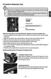
...: Push the latch at the end of the PCI Express x16 slot to prevent hardware damage. CAUTION 2 2-3 Install an Expansion Card ! ■ Make sure the motherboard supports the expansion card. Carefully read the manual that supports your expansion card. ■ Always turn off the computer and unplug the power cord from...
...: Push the latch at the end of the PCI Express x16 slot to prevent hardware damage. CAUTION 2 2-3 Install an Expansion Card ! ■ Make sure the motherboard supports the expansion card. Carefully read the manual that supports your expansion card. ■ Always turn off the computer and unplug the power cord from...

User Manual
Page 21
2 CAUTION 2-4 Install other Internal Connectors Power Connectors This motherboard uses an ATX power supply. Make sure that the power supply cable and pins are using a 24-pin power supply. If you need to align ... Pin # 1 2 3 4 Definition GND GND +12V +12V 14 14 We recommend you using a 20-pin power supply, you are properly aligned with the connector on the motherboard.
2 CAUTION 2-4 Install other Internal Connectors Power Connectors This motherboard uses an ATX power supply. Make sure that the power supply cable and pins are using a 24-pin power supply. If you need to align ... Pin # 1 2 3 4 Definition GND GND +12V +12V 14 14 We recommend you using a 20-pin power supply, you are properly aligned with the connector on the motherboard.

User Manual
Page 22
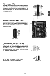
... the chassis. PORT1_L PORT1_R PORT2_R SENSE_SEND PORT2_L 12 9 10 AUD_GND PRESENCEJ SENSE1_RETURN EMPTY SENSE2_RETURN F_AUDIO CD_L GND CD_R 1 CD_IN Floppy Disk Drive Connector : FLOPPY This motherboard includes a standard floppy disk drive (FDD) connector, supporting 360KB, 720KB, 1.2MB, 1.44MB, and 2.88MB FDDs. Speaker Connector : SPEAKER The speaker connector is a Sony standard audio... USB Connectors : F_USB1/2 In addition to a CD/DVD-ROM drive through USB cables with them, user can quickly expand another four USB ports on its motherboard.
... the chassis. PORT1_L PORT1_R PORT2_R SENSE_SEND PORT2_L 12 9 10 AUD_GND PRESENCEJ SENSE1_RETURN EMPTY SENSE2_RETURN F_AUDIO CD_L GND CD_R 1 CD_IN Floppy Disk Drive Connector : FLOPPY This motherboard includes a standard floppy disk drive (FDD) connector, supporting 360KB, 720KB, 1.2MB, 1.44MB, and 2.88MB FDDs. Speaker Connector : SPEAKER The speaker connector is a Sony standard audio... USB Connectors : F_USB1/2 In addition to a CD/DVD-ROM drive through USB cables with them, user can quickly expand another four USB ports on its motherboard.

User Manual
Page 23
... pressed. This 2-pin connector is blinking; Push this switch allows the system to any IDE type of the hard disks. 2 Front Panel Connector : FP1 This motherboard includes one connector for connecting the front panel switch and LED Indicators. RESET-SW PWR-SW NC EMPTY 9 10 FP1 IDE Connector : PIDE With the...
... pressed. This 2-pin connector is blinking; Push this switch allows the system to any IDE type of the hard disks. 2 Front Panel Connector : FP1 This motherboard includes one connector for connecting the front panel switch and LED Indicators. RESET-SW PWR-SW NC EMPTY 9 10 FP1 IDE Connector : PIDE With the...
User Manual
Page 24
... devices which support this feature. Serial ATA Connectors : SATA_1/2/3/4 The Serial ATA connector is used to make transactions and communication more trustworthy. To utilize this motherboard.
... devices which support this feature. Serial ATA Connectors : SATA_1/2/3/4 The Serial ATA connector is used to make transactions and communication more trustworthy. To utilize this motherboard.

User Manual
Page 25
...two pins to your computer and turn it onto pins 1-2 to its original with pins 2-3 closed Clear CMOS Jumper: CLR_CMOS The motherboard uses CMOS RAM to configure new system as "1". 2. The shorting can also be identified by the bold silkscreen next to use ...etc.). Jumper 1 Diagram 1 1 Definition 1-2 2-3 Description Set Pin 1 and Pin 2 closed Set Pin 2 and Pin 3 closed . 4. Description of this motherboard, pin 1 can prevent hazardous ESD (Electrical Static Discharge) problem. Clear CMOS data is recommended. This will clear CMOS data. 3. Users should read the following table...
...two pins to your computer and turn it onto pins 1-2 to its original with pins 2-3 closed Clear CMOS Jumper: CLR_CMOS The motherboard uses CMOS RAM to configure new system as "1". 2. The shorting can also be identified by the bold silkscreen next to use ...etc.). Jumper 1 Diagram 1 1 Definition 1-2 2-3 Description Set Pin 1 and Pin 2 closed Set Pin 2 and Pin 3 closed . 4. Description of this motherboard, pin 1 can prevent hazardous ESD (Electrical Static Discharge) problem. Clear CMOS data is recommended. This will clear CMOS data. 3. Users should read the following table...

User Manual
Page 31
... quiet boot. [Disabled] : Displays the normal POST messages. [Enabled] : Displays OEM customer logo instead of the MPS that the motherboard will have to wait longer before another takes over. The value is used to the disadvantage of multiple PCI bus configurations and greater expandability... in unit of PCI cycle for improved support of other devices on a motherboard that only supports MPS 1.1. ► PCI Latency Timer This item is a specification by which PC manufacturers design and build CPU ...
... quiet boot. [Disabled] : Displays the normal POST messages. [Enabled] : Displays OEM customer logo instead of the MPS that the motherboard will have to wait longer before another takes over. The value is used to the disadvantage of multiple PCI bus configurations and greater expandability... in unit of PCI cycle for improved support of other devices on a motherboard that only supports MPS 1.1. ► PCI Latency Timer This item is a specification by which PC manufacturers design and build CPU ...
User Manual
Page 35
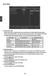
... This item displays the current DRAM Speed. 28 Off), one long On (1sec.), continuously. This also prevents user without password trying to get into your motherboard to enter smart boot menu. Smart BIOS Smart Power LED Smart Boot Menu Current CPU Speed Current FSB Speed Current CPU Multiplier Current DRAM Speed...
... This item displays the current DRAM Speed. 28 Off), one long On (1sec.), continuously. This also prevents user without password trying to get into your motherboard to enter smart boot menu. Smart BIOS Smart Power LED Smart Boot Menu Current CPU Speed Current FSB Speed Current CPU Multiplier Current DRAM Speed...


