English Manual.
Page 5
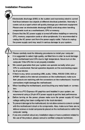
... a PCI Express x16 graphics card installed in contact with the connectors on the motherboard. Incorrect connections might damage the motherboard. ■ When handling the motherboard, avoid touching any , when connecting USB, audio, 1394a, RS232 COM, IrDA or S/PDIF cables to your CPU is overclocked. It is recommended to come in your device. ■ If there is any metal leads or connec- Also, make sure the power supply AC input voltage setting...
... a PCI Express x16 graphics card installed in contact with the connectors on the motherboard. Incorrect connections might damage the motherboard. ■ When handling the motherboard, avoid touching any , when connecting USB, audio, 1394a, RS232 COM, IrDA or S/PDIF cables to your CPU is overclocked. It is recommended to come in your device. ■ If there is any metal leads or connec- Also, make sure the power supply AC input voltage setting...

English Manual.
Page 7
... online contact Support : http://www.foxconnchannel.com/support/online.aspx CPU, Memory, VGA Compatibility Supporting Website : http://www.foxconnchannel.com/product/Motherboards/compatibility.aspx Online Update 60 Configure 63 About & Help 65 FOX LOGO 66 FOX DMI 67 Chapter 5 RAID Configuration RAID Configuration Introduction 70 Intel® Matrix Storage Manager 72 Create a RAID Driver Diskette 73 BIOS Configuration 75 Create RAID in BIOS 75 Install a New Windows XP 99 Existing Windows XP with RAID built as...
... online contact Support : http://www.foxconnchannel.com/support/online.aspx CPU, Memory, VGA Compatibility Supporting Website : http://www.foxconnchannel.com/product/Motherboards/compatibility.aspx Online Update 60 Configure 63 About & Help 65 FOX LOGO 66 FOX DMI 67 Chapter 5 RAID Configuration RAID Configuration Introduction 70 Intel® Matrix Storage Manager 72 Create a RAID Driver Diskette 73 BIOS Configuration 75 Create RAID in BIOS 75 Install a New Windows XP 99 Existing Windows XP with RAID built as...
English Manual.
Page 9
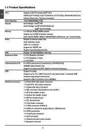
... headers supporting 8 extra ports) Supports USB 2.0 protocol up to 480Mb/s Internal Connectors 1 x 24-pin ATX main power connector 1 x 8-pin ATX 12V power connector 1 x Floppy disk drive connector 1 x IDE connector (Controlled by Jmicron361) 1 x CPU fan header (4-pin) 1 x System fan header (4-pin) 1 x NB fan header (4-pin) 1 x CD_IN connector 1 x Front Audio connector 1 x 1394a connector (P45A-S) 4 x USB 2.0 connectors (supporting 8 x USB devices) 6 x SATA connectors 1 x Front Panel connector 1 x IrDA connector 1 x Chassis intrusion alarm header 1 x Speaker...
... headers supporting 8 extra ports) Supports USB 2.0 protocol up to 480Mb/s Internal Connectors 1 x 24-pin ATX main power connector 1 x 8-pin ATX 12V power connector 1 x Floppy disk drive connector 1 x IDE connector (Controlled by Jmicron361) 1 x CPU fan header (4-pin) 1 x System fan header (4-pin) 1 x NB fan header (4-pin) 1 x CD_IN connector 1 x Front Audio connector 1 x 1394a connector (P45A-S) 4 x USB 2.0 connectors (supporting 8 x USB devices) 6 x SATA connectors 1 x Front Panel connector 1 x IrDA connector 1 x Chassis intrusion alarm header 1 x Speaker...
English Manual.
Page 10
1 Back Panel 1 x PS/2 keyboard port Connectors 1 x PS/2 mouse port 1 x ESATA port (Controlled by Jmicron361) 1 x Coaxial S/PDIF out port 1 x Serial port 1 x 1394a port (P45A-S) 4 x USB 2.0 ports 1 x RJ-45 LAN port 8-channel audio ports Hardware Monitor System voltage detection CPU/System temperature detection CPU/System fan speed detection CPU/System overheating shutdown CPU/System fan speed control PCI Express x1 Support 250MB/s (500MB/s concurrent) bandwidth Low power consumption and power management features PCI Express x16 Gen1.0 Support 4GB/s (...
1 Back Panel 1 x PS/2 keyboard port Connectors 1 x PS/2 mouse port 1 x ESATA port (Controlled by Jmicron361) 1 x Coaxial S/PDIF out port 1 x Serial port 1 x 1394a port (P45A-S) 4 x USB 2.0 ports 1 x RJ-45 LAN port 8-channel audio ports Hardware Monitor System voltage detection CPU/System temperature detection CPU/System fan speed detection CPU/System overheating shutdown CPU/System fan speed control PCI Express x1 Support 250MB/s (500MB/s concurrent) bandwidth Low power consumption and power management features PCI Express x16 Gen1.0 Support 4GB/s (...
English Manual.
Page 14
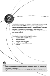
... CPU, memory, power supply, slots, pin headers and the mounting of these modules. Please refer to the motherboard layout prior to any installation and read the contents in this website for more supporting information about CPU, Memory and VGA for your motherboard : http://www.foxconnchannel.com/product/Motherboards/compatibility.aspx This chapter includes the following information : ■ Install the CPU and CPU Cooler ■ Install the Memory ■ Install an Expansion Card ■ Install other Internal Connectors...
... CPU, memory, power supply, slots, pin headers and the mounting of these modules. Please refer to the motherboard layout prior to any installation and read the contents in this website for more supporting information about CPU, Memory and VGA for your motherboard : http://www.foxconnchannel.com/product/Motherboards/compatibility.aspx This chapter includes the following information : ■ Install the CPU and CPU Cooler ■ Install the Memory ■ Install an Expansion Card ■ Install other Internal Connectors...

English Manual.
Page 20
... the PCI Express x16 slot to make any required BIOS changes for your expansion card in the expansion slot. 1. Turn on the card are completely inserted into the PCI Express x16 slot. Locate an expansion slot that came with the expansion card in the slot. 3. Installing and Removing a PCI Express x16 Graphics Card : • Installing a Graphics Card: Gently insert the graphics card into the slot. 4. Align the card with a screw. 5. After installing all expansion cards, replace the chassis cover. 6. If necessary, go to BIOS Setup...
... the PCI Express x16 slot to make any required BIOS changes for your expansion card in the expansion slot. 1. Turn on the card are completely inserted into the PCI Express x16 slot. Locate an expansion slot that came with the expansion card in the slot. 3. Installing and Removing a PCI Express x16 Graphics Card : • Installing a Graphics Card: Gently insert the graphics card into the slot. 4. Align the card with a screw. 5. After installing all expansion cards, replace the chassis cover. 6. If necessary, go to BIOS Setup...
English Manual.
Page 22
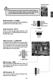
... VCC DD+ GND NC 9 10 F_USB 1/2/3/4 IDE Connector : PIDE With the provided Ultra DMA IDE ribbon cable, you need to align the ATX power connector according to any IDE type of hard disk and CD/ DVD ROM/RW drive. We recommend you using a 4-pin power supply, you can be connected to the four USB ports on the rear panel, this product also provides four 10-pin USB headers on the right. Connect a 4-pin power plug 2 Audio Connector : F_AUDIO The audio connector supports HD Audio standard.
... VCC DD+ GND NC 9 10 F_USB 1/2/3/4 IDE Connector : PIDE With the provided Ultra DMA IDE ribbon cable, you need to align the ATX power connector according to any IDE type of hard disk and CD/ DVD ROM/RW drive. We recommend you using a 4-pin power supply, you can be connected to the four USB ports on the rear panel, this product also provides four 10-pin USB headers on the right. Connect a 4-pin power plug 2 Audio Connector : F_AUDIO The audio connector supports HD Audio standard.
English Manual.
Page 23
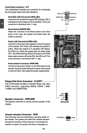
... front panel of the chassis. The Power LED indicates the system's status. This 2-pin connector is closed, the system will restart when the switch is on the front panel of the case; Push this connector. Hard Disk LED Connector (HDD-LED) Connect to the chassis front panel IDE indicator LED. When the system gets into sleep mode (S1) , the LED is used to the power button on . 2 Front Panel Connector : FP1 This motherboard includes one connector for connecting the front panel switch and LED Indicators...
... front panel of the chassis. The Power LED indicates the system's status. This 2-pin connector is closed, the system will restart when the switch is on the front panel of the case; Push this connector. Hard Disk LED Connector (HDD-LED) Connect to the chassis front panel IDE indicator LED. When the system gets into sleep mode (S1) , the LED is used to the power button on . 2 Front Panel Connector : FP1 This motherboard includes one connector for connecting the front panel switch and LED Indicators...
English Manual.
Page 25
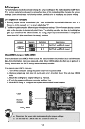
... Jumper: CLR_CMOS The motherboard uses CMOS RAM to store the basic hardware information (such as described in the power cord to your computer and turn it onto pins 1-2 to short them. 2 2-5 Jumpers For some features needed, users can change the jumper settings on the two pins to temporarily short them. Plug in next chapter. WARNING! 1 Clear 2 3 Normal 1 (Default) 2 3 CLR_CMOS ■ Disconnect the power cable before adjusting the jumper settings. ■ Do not clear the CMOS...
... Jumper: CLR_CMOS The motherboard uses CMOS RAM to store the basic hardware information (such as described in the power cord to your computer and turn it onto pins 1-2 to short them. 2 2-5 Jumpers For some features needed, users can change the jumper settings on the two pins to temporarily short them. Plug in next chapter. WARNING! 1 Clear 2 3 Normal 1 (Default) 2 3 CLR_CMOS ■ Disconnect the power cable before adjusting the jumper settings. ■ Do not clear the CMOS...

English Manual.
Page 28
... Changes and Exit Do not change fan speeds, and displays temperatures and voltages of your CPU/System. ► BIOS Security Features The Supervisor/User password can be set up through this menu to optimal default may sometimes come out an unstable system. 3 ► Power Management Setup All the items related with Green function features can be setup through this menu. ► PnP/PCI Configuration PCI/PnP features, such as less I/O cards, less memory...
... Changes and Exit Do not change fan speeds, and displays temperatures and voltages of your CPU/System. ► BIOS Security Features The Supervisor/User password can be set up through this menu to optimal default may sometimes come out an unstable system. 3 ► Power Management Setup All the items related with Green function features can be setup through this menu. ► PnP/PCI Configuration PCI/PnP features, such as less I/O cards, less memory...
English Manual.
Page 32
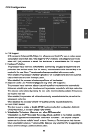
... the CPU's multiplier and voltage to lower levels when a HLT (halt) command is used to 3, it . 25 When disabled, the processor's hardware prefetcher will be [Disabled] for WinXP. ► Virtualization Technology (Appears only when CPU supports) Virtualization (i.e. CPU Configuration CMOS Setup Utility - Set Limit CPUID MaxVal to enable/disable the C1E support. ► Hardware Prefetcher The processor has a hardware prefetcher that automatically analyzes its requirements and prefetches data and instructions from the memory...
... the CPU's multiplier and voltage to lower levels when a HLT (halt) command is used to 3, it . 25 When disabled, the processor's hardware prefetcher will be [Disabled] for WinXP. ► Virtualization Technology (Appears only when CPU supports) Virtualization (i.e. CPU Configuration CMOS Setup Utility - Set Limit CPUID MaxVal to enable/disable the C1E support. ► Hardware Prefetcher The processor has a hardware prefetcher that automatically analyzes its requirements and prefetches data and instructions from the memory...

English Manual.
Page 33
... worm attempts to insert code in memory by PECI would be met, including CPU, chipset, motherboard, BIOS and operation system. The PECI bus, allowing access to this data from 2 kbit/s to 2 Mbit/s). From a control standpoint, the main difference between PECI and the previously used thermal monitoring methods is that PECI reports a negative value expressing the difference between the current temperature and the thermal throttle...
... worm attempts to insert code in memory by PECI would be met, including CPU, chipset, motherboard, BIOS and operation system. The PECI bus, allowing access to this data from 2 kbit/s to 2 Mbit/s). From a control standpoint, the main difference between PECI and the previously used thermal monitoring methods is that PECI reports a negative value expressing the difference between the current temperature and the thermal throttle...

English Manual.
Page 39
... power plane control. South Bridge Configuration CMOS Setup Utility - The SMBus specification describes the data protocols, device addresses, and electrical requirements that can better access the memory device. ► PEG Port This item is used to 2 seconds] Enabled Disabled Move Enter:Select +/-/:Value F10:Save ESC:Exit F1:General Help F9:Optimized Defaults ► SMBUS Controller The System Management Bus is a specific implementation of DRAM timing by SPD device. Assertion Width [1 to enable/disable PCI Express graphics port...
... power plane control. South Bridge Configuration CMOS Setup Utility - The SMBus specification describes the data protocols, device addresses, and electrical requirements that can better access the memory device. ► PEG Port This item is used to 2 seconds] Enabled Disabled Move Enter:Select +/-/:Value F10:Save ESC:Exit F1:General Help F9:Optimized Defaults ► SMBUS Controller The System Management Bus is a specific implementation of DRAM timing by SPD device. Assertion Width [1 to enable/disable PCI Express graphics port...
English Manual.
Page 41
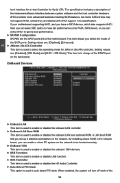
... enable or disable USB function. ► HDA Controller This item is used to enable or disable the HD Audio Controller. ► Auto Detect PCI Clock This option is used to enable or disable the onboard LAN boot optional ROM. This item is used to get its specification. By installing a boot ROM in the network board, you select the mode of the SATA ports. Setting values are labeled with AHCI support in charge of the motherboard. A LAN boot ROM lets you can select IDE option to select the operating mode for Serial ATA. Setting...
... enable or disable USB function. ► HDA Controller This item is used to enable or disable the HD Audio Controller. ► Auto Detect PCI Clock This option is used to enable or disable the onboard LAN boot optional ROM. This item is used to get its specification. By installing a boot ROM in the network board, you select the mode of the SATA ports. Setting values are labeled with AHCI support in charge of the motherboard. A LAN boot ROM lets you can select IDE option to select the operating mode for Serial ATA. Setting...
English Manual.
Page 47
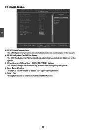
... fan speed are automatically detected and displayed by the system. ► VCore/Memory Voltage/Vcc + 3.30V/+12.0V/MCH Voltage The current voltages are automatically detected and displayed by the system. ► Case Open Warning This item is used to enable or disable case open warning function. ► Smart Fan This option is used to enable or disable smart fan function. 40 Copyright (C) 1985-2005, American Megatrends, Inc. 3 PC Health Status CMOS Setup Utility...
... fan speed are automatically detected and displayed by the system. ► VCore/Memory Voltage/Vcc + 3.30V/+12.0V/MCH Voltage The current voltages are automatically detected and displayed by the system. ► Case Open Warning This item is used to enable or disable case open warning function. ► Smart Fan This option is used to enable or disable smart fan function. 40 Copyright (C) 1985-2005, American Megatrends, Inc. 3 PC Health Status CMOS Setup Utility...

English Manual.
Page 51
... your CD/DVD-ROM drive, and the main menu will be displayed on your PC screen to guide you to change your system without going to install all the drivers for your computer after all the drivers have been installed. Software Utilities Use these options to BIOS. Some auto features help user to restart your system. You should install the drivers in order, and you need to improve (or overclock) your system setting without...
... your CD/DVD-ROM drive, and the main menu will be displayed on your PC screen to guide you to change your system without going to install all the drivers for your computer after all the drivers have been installed. Software Utilities Use these options to BIOS. Some auto features help user to restart your system. You should install the drivers in order, and you need to improve (or overclock) your system setting without...
English Manual.
Page 82
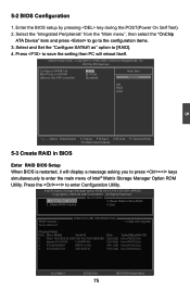
... Menu Press to save the setting then PC will display a message asking you to press + keys simultaneously to the configuration items. 3. Delete RAID Volume 4. Reset Disks to enter Configuration Utility. Enter the BIOS setup by pressing key during the POST(Power On Self Test). 2. CMOS Setup Utility - 5-2 BIOS Configuration 1. Select the "Integrated Peripherals" from the "Main menu", then select the "OnChip ATA Device" item and press to go to enter the main menu of Intel® Matrix Storage Manager Option ROM Utility...
... Menu Press to save the setting then PC will display a message asking you to press + keys simultaneously to the configuration items. 3. Delete RAID Volume 4. Reset Disks to enter Configuration Utility. Enter the BIOS setup by pressing key during the POST(Power On Self Test). 2. CMOS Setup Utility - 5-2 BIOS Configuration 1. Select the "Integrated Peripherals" from the "Main menu", then select the "OnChip ATA Device" item and press to go to enter the main menu of Intel® Matrix Storage Manager Option ROM Utility...

English Manual.
Page 106
... Boot Device Try Other Boot Devices [CD/DVD:6S-DVD-ROM] ] [HDD:6M-HDS728080PL] [1st FLOPPY DRIVE] [No] Specify the boot sequence from the available devices. Press to "CDROM", save changes and exit the BIOS setup. Windows Setup 5 Press F6 if you forgot to do this, PC will start installing Windows Operating System. CAUTION 5-4 Install a New Windows XP ! CMOS Setup Utility - Move Enter:Select +/-/:Value F10:Save ESC:Exit F1:General Help F9:Optimized Defaults 4. Watch the screen...
... Boot Device Try Other Boot Devices [CD/DVD:6S-DVD-ROM] ] [HDD:6M-HDS728080PL] [1st FLOPPY DRIVE] [No] Specify the boot sequence from the available devices. Press to "CDROM", save changes and exit the BIOS setup. Windows Setup 5 Press F6 if you forgot to do this, PC will start installing Windows Operating System. CAUTION 5-4 Install a New Windows XP ! CMOS Setup Utility - Move Enter:Select +/-/:Value F10:Save ESC:Exit F1:General Help F9:Optimized Defaults 4. Watch the screen...
English Manual.
Page 107
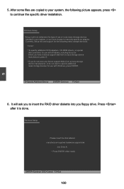
... additional mass storage devices for which you have a device support disk from a mass storage device manufacturer, press S. * If you floppy drive. Press after it is done. Windows Setup Setup could not determine the type of one or more mass storage devices installed in your system, the following mass storage device(s): * To specify additional SCSI adapters, CD-ROM drivers, or special disk controllers for use with Windows, including those for use with Windows, press ENTER. It will load support for...
... additional mass storage devices for which you have a device support disk from a mass storage device manufacturer, press S. * If you floppy drive. Press after it is done. Windows Setup Setup could not determine the type of one or more mass storage devices installed in your system, the following mass storage device(s): * To specify additional SCSI adapters, CD-ROM drivers, or special disk controllers for use with Windows, including those for use with Windows, press ENTER. It will load support for...
English Manual.
Page 109
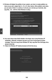
... in the floppy drive during Windows XP installation, otherwise, Windows may copy files from the floppy drive, please remember. 11. Windows XP Professional Setup Insert the disk labeled: Intel Matrix Storage Manager driver into drive A: * Press ENTER when ready F3=Quit ENTER=Continue 102 5 9. Follow the Windows XP install processes to format your system, you have to select an item in the list. ● To set up Windows XP on this...
... in the floppy drive during Windows XP installation, otherwise, Windows may copy files from the floppy drive, please remember. 11. Windows XP Professional Setup Insert the disk labeled: Intel Matrix Storage Manager driver into drive A: * Press ENTER when ready F3=Quit ENTER=Continue 102 5 9. Follow the Windows XP install processes to format your system, you have to select an item in the list. ● To set up Windows XP on this...


