
Cleaning & Maintenance
Page 2
... and, if not installed and used in accordance with the limits for a Class B digital device, pursuant to which the receiver is no guarantee that to Part 15 of the following measures: • Reorient or relocate the receiving antenna. • Increase the separation between the equipment and receiver. • Connect the equipment...
... and, if not installed and used in accordance with the limits for a Class B digital device, pursuant to which the receiver is no guarantee that to Part 15 of the following measures: • Reorient or relocate the receiving antenna. • Increase the separation between the equipment and receiver. • Connect the equipment...

Cleaning & Maintenance
Page 3
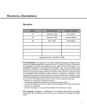
... contents of this manual may be 3 meters (10 feet) or less. Copyrights All Rights Reserved, Copyright © 2000, FUJITSU LIMITED. As an ENERGYSTAR ® Partner, Fujitsu Limited declares that this manual may be 3 meters (10 feet) or less. ii Cet appareil numérique de la...length of the power cord must be revised without prior notice. No part of this scanner meets the ENERGYSTAR ® guidelines for energy efficiency. Printed in any products herein, to any form without obligation. FUJITSU reserves the right to make changes to improve reliability, function, or ...
... contents of this manual may be 3 meters (10 feet) or less. Copyrights All Rights Reserved, Copyright © 2000, FUJITSU LIMITED. As an ENERGYSTAR ® Partner, Fujitsu Limited declares that this manual may be 3 meters (10 feet) or less. ii Cet appareil numérique de la...length of the power cord must be revised without prior notice. No part of this scanner meets the ENERGYSTAR ® guidelines for energy efficiency. Printed in any products herein, to any form without obligation. FUJITSU reserves the right to make changes to improve reliability, function, or ...
Cleaning & Maintenance
Page 7
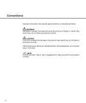
CAUTION CAUTION indicates that personal injury like pinching of fingers or hands may result if you do not follow a procedure correctly. Official Fujitsu part names are indicated with an initial capital letter, as follows: WARNING WARNING indicates that damage to help you do not follow a procedure correctly. Conventions Important information that requires special attention is indicated as in the part name "Pick roller". NOTE A NOTE provides "how-to" tips or suggestions to the scanner may result if you perform a procedure correctly. vi
CAUTION CAUTION indicates that personal injury like pinching of fingers or hands may result if you do not follow a procedure correctly. Official Fujitsu part names are indicated with an initial capital letter, as follows: WARNING WARNING indicates that damage to help you do not follow a procedure correctly. Conventions Important information that requires special attention is indicated as in the part name "Pick roller". NOTE A NOTE provides "how-to" tips or suggestions to the scanner may result if you perform a procedure correctly. vi

Cleaning & Maintenance
Page 8
CONTENTS CHAPTER 1 DESCRIPTION 1-1 Units 1-2 Assemblies 1-4 Operator panel 1-5 Panel Display 1-6 CHAPTER 2 CLEANING 2-1 Cleaning Supplies and Areas Requiring Cleaning .......... 2-2 Supplies 2-2 Areas Requiring Cleaning 2-3 Cleaning the ADF 2-4 Cleaning the Flatbed 2-10 CHAPTER 3 REPLACEMENT OF PARTS 3-1 Pad Assembly 3-2 Pick Roller 3-4 CHAPTER 4 TROUBLESHOOTING 4-1 Clearing Paper Jams 4-2 Initial Checks 4-3 Problem Checklist 4-20 vii
CONTENTS CHAPTER 1 DESCRIPTION 1-1 Units 1-2 Assemblies 1-4 Operator panel 1-5 Panel Display 1-6 CHAPTER 2 CLEANING 2-1 Cleaning Supplies and Areas Requiring Cleaning .......... 2-2 Supplies 2-2 Areas Requiring Cleaning 2-3 Cleaning the ADF 2-4 Cleaning the Flatbed 2-10 CHAPTER 3 REPLACEMENT OF PARTS 3-1 Pad Assembly 3-2 Pick Roller 3-4 CHAPTER 4 TROUBLESHOOTING 4-1 Clearing Paper Jams 4-2 Initial Checks 4-3 Problem Checklist 4-20 vii

Cleaning & Maintenance
Page 9
CHAPTER 1 CHAPTER 2 CHAPTER 3 CHAPTER 4 DESCRIPTION CLEANING REPLACEMENT OF PARTS TROUBLESHOOTING TROUBLESHOOTING REPLACEMENT OF PARTS CLEANING D DEESSCCRRIIPTPITOINON
CHAPTER 1 CHAPTER 2 CHAPTER 3 CHAPTER 4 DESCRIPTION CLEANING REPLACEMENT OF PARTS TROUBLESHOOTING TROUBLESHOOTING REPLACEMENT OF PARTS CLEANING D DEESSCCRRIIPTPITOINON

Cleaning & Maintenance
Page 15
... feed, pressing the "Stop" button turns off "Check" and returns to the "Scanner Ready" screen). Moves the cursor (blinking part) to the left Moves the cursor (blinking part) to the right Exit When you immediately to read. Stop When the "Check" LED lights, pressing this button returns you are... this button releases the error status (turns off the "Check" lamp. • If it blinks at four second intervals, this indicates cleaning the ADF is used . while Manual start mode is set or "the Read" lamp lights when the video interface option is necessary. 1-6 If the problem is...
... feed, pressing the "Stop" button turns off "Check" and returns to the "Scanner Ready" screen). Moves the cursor (blinking part) to the left Moves the cursor (blinking part) to the right Exit When you immediately to read. Stop When the "Check" LED lights, pressing this button returns you are... this button releases the error status (turns off the "Check" lamp. • If it blinks at four second intervals, this indicates cleaning the ADF is used . while Manual start mode is set or "the Read" lamp lights when the video interface option is necessary. 1-6 If the problem is...

Cleaning & Maintenance
Page 16
... in one time. NOTE When the counter value is 0, no number is automatically reset at every 10 sheets. How to check the cleaning cycle or parts replacement cycle. This counter increments at the start of sheets scanned at one day. The counter is displayed. 1-7 When the button is pressed This counter...
... in one time. NOTE When the counter value is 0, no number is automatically reset at every 10 sheets. How to check the cleaning cycle or parts replacement cycle. This counter increments at the start of sheets scanned at one day. The counter is displayed. 1-7 When the button is pressed This counter...
Cleaning & Maintenance
Page 23
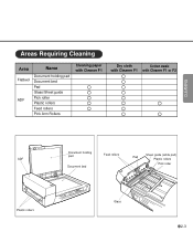
CLEANING Areas Requiring Cleaning Area Name Flatbed ADF Document holding pad Document bed Pad Glass/Sheet guide Pick roller Plastic rollers Feed rollers Pick Arm Rollers Cleaning paper with Cleaner F1 Dry cloth Cotton swab with Cleaner F1 with Cleaner F1 or F2 ADF Plastic rollers Document holding pad Document bed Feed rollers Sheet guide (white part) Pad Plastic rollers Pick roller Glass 2-3
CLEANING Areas Requiring Cleaning Area Name Flatbed ADF Document holding pad Document bed Pad Glass/Sheet guide Pick roller Plastic rollers Feed rollers Pick Arm Rollers Cleaning paper with Cleaner F1 Dry cloth Cotton swab with Cleaner F1 with Cleaner F1 or F2 ADF Plastic rollers Document holding pad Document bed Feed rollers Sheet guide (white part) Pad Plastic rollers Pick roller Glass 2-3
Cleaning & Maintenance
Page 27
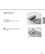
Sheet guide (white part) NOTE If the Sheet guide is dirty, the front image may show vertical stripes. 3 Close the ADF to lock the ADF lever. 2-7 CLEANING Sheet guide (white part): Wipe the sheet guide.
Sheet guide (white part) NOTE If the Sheet guide is dirty, the front image may show vertical stripes. 3 Close the ADF to lock the ADF lever. 2-7 CLEANING Sheet guide (white part): Wipe the sheet guide.

Cleaning & Maintenance
Page 31
CHAPTER 3 REPLACEMENT OF PARTS This chapter describes how to replace the pad assembly and the pick roller. Pad Assembly Pick Roller 3-1
CHAPTER 3 REPLACEMENT OF PARTS This chapter describes how to replace the pad assembly and the pick roller. Pad Assembly Pick Roller 3-1

Cleaning & Maintenance
Page 33
NOTE Hold both ends of step 3. NOTE Fit the Pad assembly pin into the larger hole, then slide it to the left photo. REPLACEMENT OF PARTS 3 Slide the Pad Assembly to the right until it stops. 5 Close the ADF. 3-3 CAUTION Don't hold the sensor arm with the Pad assembly. Pad assembly 4 Attach the Pad Assembly to hook the Pad spring, remove the Pad Assembly. Then, being careful not to the ADF in the reverse sequence of the Pad assembly as shown in the left and pull it towards you.
NOTE Hold both ends of step 3. NOTE Fit the Pad assembly pin into the larger hole, then slide it to the left photo. REPLACEMENT OF PARTS 3 Slide the Pad Assembly to the right until it stops. 5 Close the ADF. 3-3 CAUTION Don't hold the sensor arm with the Pad assembly. Pad assembly 4 Attach the Pad Assembly to hook the Pad spring, remove the Pad Assembly. Then, being careful not to the ADF in the reverse sequence of the Pad assembly as shown in the left and pull it towards you.

Cleaning & Maintenance
Page 35
Then lift the right side of the cover and remove it. 4 To remove the Pick rollers, turn the stopper counterclockwise. 3 With both hands, lift up Guide A and disengage its tip from the right hole. Stopper Pick roller 2 Pick roller 1 REPLACEMENT OF PARTS Position for Replacement 3-5
Then lift the right side of the cover and remove it. 4 To remove the Pick rollers, turn the stopper counterclockwise. 3 With both hands, lift up Guide A and disengage its tip from the right hole. Stopper Pick roller 2 Pick roller 1 REPLACEMENT OF PARTS Position for Replacement 3-5

Cleaning & Maintenance
Page 37
NOTE Pick roller 1 has a groove in its rubber. Then, slide Pick roller 1 toward the right side. NOTE Make sure that the shaft is securely fixed to the bearings. 3-7 REPLACEMENT OF PARTS 7 To attach the new Pick rollers, place Pick roller 1 from the right side above the bearing for Pick roller 1. Put the shaft of Pick roller 1 into the bearing.
NOTE Pick roller 1 has a groove in its rubber. Then, slide Pick roller 1 toward the right side. NOTE Make sure that the shaft is securely fixed to the bearings. 3-7 REPLACEMENT OF PARTS 7 To attach the new Pick rollers, place Pick roller 1 from the right side above the bearing for Pick roller 1. Put the shaft of Pick roller 1 into the bearing.

Cleaning & Maintenance
Page 39
Stopper REPLACEMENT OF PARTS Operating Position 3-9 9 Turn the stopper clockwise to secure the Pick rollers.
Stopper REPLACEMENT OF PARTS Operating Position 3-9 9 Turn the stopper clockwise to secure the Pick rollers.

Cleaning & Maintenance
Page 47
Clean the dirty parts. (See p. 2-5, p. 2-7, p. 2-10) YES Contact the manufacturer's authorized service center. TROUBLESHOOTING 4-7 4 Symptom Pictures and photographs are not read correctly. NO Select the halftone or dithering mode from the host computer. Is the "Photo" mode selected? YES Are the Document bed, NO Document holding pad, glass, and sheet guides clean? NO Select the "Photo" mode (White level following "Off") through the scanner setting menu in the software. YES Is halftone or dither processing selected?
Clean the dirty parts. (See p. 2-5, p. 2-7, p. 2-10) YES Contact the manufacturer's authorized service center. TROUBLESHOOTING 4-7 4 Symptom Pictures and photographs are not read correctly. NO Select the halftone or dithering mode from the host computer. Is the "Photo" mode selected? YES Are the Document bed, NO Document holding pad, glass, and sheet guides clean? NO Select the "Photo" mode (White level following "Off") through the scanner setting menu in the software. YES Is halftone or dither processing selected?

Cleaning & Maintenance
Page 48
via software. Clean the dirty parts. (See p. 2-5, p. 2-7, p. 2-10) YES Contact the manufacturer's authorized service center. 4-8 NO Are the Document bed, NO Document holding pad, glass, and sheet guides clean? 5 Symptom Characters and lines are not read correctly. YES 3mm YES Is there any printed text on Select the "Photo" mode the first 3mm of the (White level following "Off") document? NO Select the "Line Art" mode from the host computer. Is the "Line Art" mode selected?
via software. Clean the dirty parts. (See p. 2-5, p. 2-7, p. 2-10) YES Contact the manufacturer's authorized service center. 4-8 NO Are the Document bed, NO Document holding pad, glass, and sheet guides clean? 5 Symptom Characters and lines are not read correctly. YES 3mm YES Is there any printed text on Select the "Photo" mode the first 3mm of the (White level following "Off") document? NO Select the "Line Art" mode from the host computer. Is the "Line Art" mode selected?

Cleaning & Maintenance
Page 49
...the scanner on it . 6 Symptom Images are any rubber feet of the scanner missing? YES Do not press the top of the ADF being pressed or is there anything heavy on an even NO and flat surface or are distorted or unclear. YES missing NO Is the ...scanner on it ? Contact the manufacturer's authorized service center. TROUBLESHOOTING 4-9 Clean the dirty parts. (See p. 2-5, p. 2-7, p. 2-10) YES During rear read operation with the ADF, is the top of the ADF or put anything heavy on a flat, even surface or attach the rubber feet. Are the Document bed, ...
...the scanner on it . 6 Symptom Images are any rubber feet of the scanner missing? YES Do not press the top of the ADF being pressed or is there anything heavy on an even NO and flat surface or are distorted or unclear. YES missing NO Is the ...scanner on it ? Contact the manufacturer's authorized service center. TROUBLESHOOTING 4-9 Clean the dirty parts. (See p. 2-5, p. 2-7, p. 2-10) YES During rear read operation with the ADF, is the top of the ADF or put anything heavy on a flat, even surface or attach the rubber feet. Are the Document bed, ...

Cleaning & Maintenance
Page 60
... This example shows the revision A2. 4-20 Problem Checklist Before contacting the manufacturer's authorized service center, please fill in the following items. General Model Part number Serial number Manufactured data Revision A 0123456789 B 0123456789 C 0123456789 Date of document. Image error Interface controller model Software/application name Can you send ...the original and output of the back. Serviced before (when and how)? The revision is indicated by mail? (Example) M4097D (Example) CA02956-2300 (Example) 00002 (Example) 2000-2 The revision is your daily usage?
... This example shows the revision A2. 4-20 Problem Checklist Before contacting the manufacturer's authorized service center, please fill in the following items. General Model Part number Serial number Manufactured data Revision A 0123456789 B 0123456789 C 0123456789 Date of document. Image error Interface controller model Software/application name Can you send ...the original and output of the back. Serviced before (when and how)? The revision is indicated by mail? (Example) M4097D (Example) CA02956-2300 (Example) 00002 (Example) 2000-2 The revision is your daily usage?

Operator's Guide
Page 3
i NOTICE • The use of a non-shielded interface cable with the limits for a Class B digital device, pursuant to Part 15 of the following measures: • Reorient or relocate the receiving antenna. • Increase the separation between the equipment and receiver. • Connect the equipment ...
i NOTICE • The use of a non-shielded interface cable with the limits for a Class B digital device, pursuant to Part 15 of the following measures: • Reorient or relocate the receiving antenna. • Increase the separation between the equipment and receiver. • Connect the equipment ...

Operator's Guide
Page 4
S. The contents of this scanner meets ENERGYSTAR ® guidelines for energy efficiency. ENERGYSTAR ® is a U. ii Cet appareil numérique de la classe B est conformme à la norme NMB-003 du Canada. registered mark. All Rights Reserved, Copyright © 2000 FUJITSU LIMITED. Printed in any form without prior notice. This Class B digital apparatus complies with Canadian ICES-003. As an ENERGYSTAR ® Partner, Fujitsu Limited has determined that this manual may be reproduced in Japan. No part of this manual may be revised without permission.
S. The contents of this scanner meets ENERGYSTAR ® guidelines for energy efficiency. ENERGYSTAR ® is a U. ii Cet appareil numérique de la classe B est conformme à la norme NMB-003 du Canada. registered mark. All Rights Reserved, Copyright © 2000 FUJITSU LIMITED. Printed in any form without prior notice. This Class B digital apparatus complies with Canadian ICES-003. As an ENERGYSTAR ® Partner, Fujitsu Limited has determined that this manual may be reproduced in Japan. No part of this manual may be revised without permission.


