Cleaning & Maintenance
Page 12
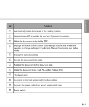
... the operator to change settings in Feed mode, Manual Feed mode, and Setup mode. 5 Stacks the read documents. 6 Covers the document to be read. 7 Presses the document to the Document bed. 8 Holds the document to be fed by ADF. 4 Displays the status of jammed documents. 3 Holds the documents to... be read. Also called Flatbed (FB). 9 Third party slot. 10 Connects to the host system with interface cables. 11 Connect the power ...
... the operator to change settings in Feed mode, Manual Feed mode, and Setup mode. 5 Stacks the read documents. 6 Covers the document to be read. 7 Presses the document to the Document bed. 8 Holds the document to be fed by ADF. 4 Displays the status of jammed documents. 3 Holds the documents to... be read. Also called Flatbed (FB). 9 Third party slot. 10 Connects to the host system with interface cables. 11 Connect the power ...

Operator's Guide
Page 7
...) image sensors. This manual contains chapters on OPERATING INSTRUCTIONS, CLEANING, REPLACEMENT OF PARTS, ADJUSTMENT and TROUBLESHOOTING. The M4097D is a very fast and highly functional image scanner developed for information about the routine operation of Terms and an Index.... Refer to use the M4097D image scanner. v The Reference Guide contains chapters on the following topics: COMPONENTS INSTALLATION AND CONNECTIONS OPERATING INSTRUCTIONS ADF DOCUMENT SPECIFICATIONS SCANNER SPECFICATIONS SETUP MODE It also contains a Glossary of the M4097D. This scanner features duplex ...
...) image sensors. This manual contains chapters on OPERATING INSTRUCTIONS, CLEANING, REPLACEMENT OF PARTS, ADJUSTMENT and TROUBLESHOOTING. The M4097D is a very fast and highly functional image scanner developed for information about the routine operation of Terms and an Index.... Refer to use the M4097D image scanner. v The Reference Guide contains chapters on the following topics: COMPONENTS INSTALLATION AND CONNECTIONS OPERATING INSTRUCTIONS ADF DOCUMENT SPECIFICATIONS SCANNER SPECFICATIONS SETUP MODE It also contains a Glossary of the M4097D. This scanner features duplex ...

Operator's Guide
Page 10
❑ CHAPTER 7 SETUP MODE Activating the Setup Mode 7-1 Contents of the Setup Mode 7-2 ❑ GLOSSARY OF TERMS GL-1 ❑ INDEX IN-1 ❑ Declarations of Conformity DE-1 viii
❑ CHAPTER 7 SETUP MODE Activating the Setup Mode 7-1 Contents of the Setup Mode 7-2 ❑ GLOSSARY OF TERMS GL-1 ❑ INDEX IN-1 ❑ Declarations of Conformity DE-1 viii

Operator's Guide
Page 11
COMPONENTS COMPONENTS INSTALLATION AND INSTALLATION AND CONNECTIONS CONNECTIONS OPERATING INSTRUCTION OPERATING INSTRUCTION DOCUMENT SPECIFICATION DOCUMENT SPECIFICATION SCANNER SPECIFICATIONS SPECIFICATIONS CONSUMABLES AND CONSUMABLES AND OPTIONS OPTIONS SETUP MODE SETUP MODE GLOSSARY OF TERMS INDEX GLOSSARY OF TERMS INDEX ix
COMPONENTS COMPONENTS INSTALLATION AND INSTALLATION AND CONNECTIONS CONNECTIONS OPERATING INSTRUCTION OPERATING INSTRUCTION DOCUMENT SPECIFICATION DOCUMENT SPECIFICATION SCANNER SPECIFICATIONS SPECIFICATIONS CONSUMABLES AND CONSUMABLES AND OPTIONS OPTIONS SETUP MODE SETUP MODE GLOSSARY OF TERMS INDEX GLOSSARY OF TERMS INDEX ix

Operator's Guide
Page 33
... of the LCD. 2 Then press the "Next" button. The scanner displays "Mode select 2" meaning that the setup mode is 5. NOTICE If no other device is using the Setup mode of the SCSI ID is ready. 4 Then press the "Enter" button several times. The procedure to change terminator. The scanner ...displays the following: 5 Press the "Next" button around times, then the scanner displays "SCSI ID" on the lower line of the...
... of the LCD. 2 Then press the "Next" button. The scanner displays "Mode select 2" meaning that the setup mode is 5. NOTICE If no other device is using the Setup mode of the SCSI ID is ready. 4 Then press the "Enter" button several times. The procedure to change terminator. The scanner ...displays the following: 5 Press the "Next" button around times, then the scanner displays "SCSI ID" on the lower line of the...

Operator's Guide
Page 39
..., the scanner waits for setting the manual feed mode are read. This predetermined time (time-out limit) is in the Setup mode. Therefore you can set the next documents on the ADF chute without issuing a "Paper Empty" message after all documents are as follows: 1 Turn the power ON and verify that "Scanner...
..., the scanner waits for setting the manual feed mode are read. This predetermined time (time-out limit) is in the Setup mode. Therefore you can set the next documents on the ADF chute without issuing a "Paper Empty" message after all documents are as follows: 1 Turn the power ON and verify that "Scanner...

Operator's Guide
Page 67
... power ON and verify that "Scanner Ready" is not required. NOTICE When the video interface option is Installed This section describes the button specifications and setup details for each of the simplex (front-side), duplex (front-side) and duplex (back-side) reading modes when the scanner has the video interface option... host computer, the following button operation is displayed on the LCD. 2 Press then the scanner displays Screen M2. 3 Press then the scanner displays Screen 1. 4 Select ADF or FB by pressing or . Then press Enter.
... power ON and verify that "Scanner Ready" is not required. NOTICE When the video interface option is Installed This section describes the button specifications and setup details for each of the simplex (front-side), duplex (front-side) and duplex (back-side) reading modes when the scanner has the video interface option... host computer, the following button operation is displayed on the LCD. 2 Press then the scanner displays Screen M2. 3 Press then the scanner displays Screen 1. 4 Select ADF or FB by pressing or . Then press Enter.

Operator's Guide
Page 72
CHAPTER 7 SETUP MODE This chapter describes the setup mode of the Setup Mode Activating the Setup Mode Contents of the scanner.
CHAPTER 7 SETUP MODE This chapter describes the setup mode of the Setup Mode Activating the Setup Mode Contents of the scanner.

Operator's Guide
Page 73
Then the scanner displays "Scanner Ready" on the LCD. 2 If the scanner does not have a video interface option, go to the "Scanner Ready" screen. 7-1 Press then the scanner with the video interface option displays Screen M2. 3 Press then the scanner displays Screen M3. 4 Press then the scanner displays Screen M4. 5 Press . NOTICE Any time you press , you can return to the procedure step 3. Now the scanner is at Screen 41 (page 6-3) in Setup mode. Activating the Setup Mode This section describes how to activate the setup mode. 1 Turn the power ON.
Then the scanner displays "Scanner Ready" on the LCD. 2 If the scanner does not have a video interface option, go to the "Scanner Ready" screen. 7-1 Press then the scanner with the video interface option displays Screen M2. 3 Press then the scanner displays Screen M3. 4 Press then the scanner displays Screen M4. 5 Press . NOTICE Any time you press , you can return to the procedure step 3. Now the scanner is at Screen 41 (page 6-3) in Setup mode. Activating the Setup Mode This section describes how to activate the setup mode. 1 Turn the power ON.
Operator's Guide
Page 74
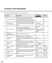
Contents of the Setup Mode This section describes the contents of the front side image when using the H:-2 to +3 mm ADF. Double feed is specified. User can select the most comfortable Pick start time setting 6 Time-out limit setting 7 ADF front offset setting* 8 ADF back offset setting* 9 Flatbed offset setting* Description Selectable parameters Default Specifies...
Contents of the Setup Mode This section describes the contents of the front side image when using the H:-2 to +3 mm ADF. Double feed is specified. User can select the most comfortable Pick start time setting 6 Time-out limit setting 7 ADF front offset setting* 8 ADF back offset setting* 9 Flatbed offset setting* Description Selectable parameters Default Specifies...

Operator's Guide
Page 81
Then press to activate the setting. Then press to activate the setting. The scanner displays the next item of the setup mode. 7-9 The scanner displays Screen C. 5 At Screen C, press to increase the offset or press to default, select "Yes" otherwise "No" then press . 3 At Screen A, if you want to let the offset return to decrease the offset. The increment or decrement is 0.5 mm. The scanner displays Screen B. 4 At Screen B, press to increase the offset or press to decrease offset.
Then press to activate the setting. Then press to activate the setting. The scanner displays the next item of the setup mode. 7-9 The scanner displays Screen C. 5 At Screen C, press to increase the offset or press to default, select "Yes" otherwise "No" then press . 3 At Screen A, if you want to let the offset return to decrease the offset. The increment or decrement is 0.5 mm. The scanner displays Screen B. 4 At Screen B, press to increase the offset or press to decrease offset.
Operator's Guide
Page 91
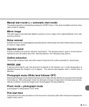
This warning also appears when a double feed is read image is symmetrically flipped to control scanner operations such as loading document, selecting features, and changing setup options. Photo mode = photograph mode A photograph is detected. Pick start mode) The reading operation is installed. Mirror image The read properly in this mode. GL-5 ...
This warning also appears when a double feed is read image is symmetrically flipped to control scanner operations such as loading document, selecting features, and changing setup options. Photo mode = photograph mode A photograph is detected. Pick start mode) The reading operation is installed. Mirror image The read properly in this mode. GL-5 ...
Operator's Guide
Page 92
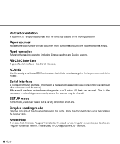
...feet) can view or set a variety of the document is often necessary in networking environments, where the scanner may be used for example. SETUP mode In this mode. Simplex reading mode Only the front side of function in this mode, users can be shared. Serial interface A standard... document from slanted lines and curves. Paper counter Indicates the total number of reading until the hopper becomes empty. SCSI-ID Used to specify a particular SCSI device when the initiator selects a target or the target reconnects to the reading operation including Simplex reading and Duplex reading...
...feet) can view or set a variety of the document is often necessary in networking environments, where the scanner may be used for example. SETUP mode In this mode. Simplex reading mode Only the front side of function in this mode, users can be shared. Serial interface A standard... document from slanted lines and curves. Paper counter Indicates the total number of reading until the hopper becomes empty. SCSI-ID Used to specify a particular SCSI device when the initiator selects a target or the target reconnects to the reading operation including Simplex reading and Duplex reading...

Operator's Guide
Page 95
INDEX A A3 3-3 A4 3-3 Abrasion counter 1-7 Activating the Setup mode 7-1 ADF 1-2, 1-3 ADF lever 1-2, 1-3 mode 1-6 paper chute 1-2 Alarm 1-10 Ambient condition 5-1 Arrangement 1-5 Assemblies 1-4 B Belt 5-3 Button /LED Function 1-6 C Cable connection 2-5 Carrier fixing bracket 2-4 Checking the components 1-1 Connecting the interface cable 2-6 the power cable 2-5 Consumables 5-3 Contents of the Setup mode 6-2 Conventions iii D Density 3-3, 3-4 Dimentions 5-1, 5-2 DLT (Double letter) 3-3 Document bed 1-2, 1-3 holding...
INDEX A A3 3-3 A4 3-3 Abrasion counter 1-7 Activating the Setup mode 7-1 ADF 1-2, 1-3 ADF lever 1-2, 1-3 mode 1-6 paper chute 1-2 Alarm 1-10 Ambient condition 5-1 Arrangement 1-5 Assemblies 1-4 B Belt 5-3 Button /LED Function 1-6 C Cable connection 2-5 Carrier fixing bracket 2-4 Checking the components 1-1 Connecting the interface cable 2-6 the power cable 2-5 Consumables 5-3 Contents of the Setup mode 6-2 Conventions iii D Density 3-3, 3-4 Dimentions 5-1, 5-2 DLT (Double letter) 3-3 Document bed 1-2, 1-3 holding...
Operator's Guide
Page 96
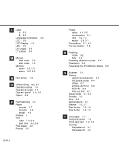
... 1-6 R Reading mode 3-2 face 3-2 Resetting abrasion counter 6-6 Resolution 3-3 Reviewing the IPC/Memory Status 6-9 S Scanner 1-1 Setting double feed detection 6-3 IPC preset mode 6-4 Offset 6-7 picking start time 6-6 SCSI-ID 6-9 time-out limit 6-7 Setup mode 6-1, 6-2 Simplex 3-2 Size 3-3 Specifications 5-1 Stacker 1-2, 2-7 Start button 1-5, 1-6 Stop button 1-5, 1-6 T Terminator 1-1 Temporary error 1-9 Third party slot 1-2, 1-3 Turning the power on 3-1 the power off...
... 1-6 R Reading mode 3-2 face 3-2 Resetting abrasion counter 6-6 Resolution 3-3 Reviewing the IPC/Memory Status 6-9 S Scanner 1-1 Setting double feed detection 6-3 IPC preset mode 6-4 Offset 6-7 picking start time 6-6 SCSI-ID 6-9 time-out limit 6-7 Setup mode 6-1, 6-2 Simplex 3-2 Size 3-3 Specifications 5-1 Stacker 1-2, 2-7 Start button 1-5, 1-6 Stop button 1-5, 1-6 T Terminator 1-1 Temporary error 1-9 Third party slot 1-2, 1-3 Turning the power on 3-1 the power off...
