
Manual/User Guide
Page 6
...the MHL Series and MHM Series. C141-E104-03EN i Preface This manual describes the MHL Series and MHM Series, 2.5-inch hard disk drives. CHAPTER 3 Installation Conditions This chapter describes the external dimensions, installation conditions, and switch settings of the systems in controller ...that the reader has a basic knowledge of hard disk drives and their features. CHAPTER 5 Interface This chapter describes the interface specifications of the MHL Series and MHM Series. CHAPTER 6...
...the MHL Series and MHM Series. C141-E104-03EN i Preface This manual describes the MHL Series and MHM Series, 2.5-inch hard disk drives. CHAPTER 3 Installation Conditions This chapter describes the external dimensions, installation conditions, and switch settings of the systems in controller ...that the reader has a basic knowledge of hard disk drives and their features. CHAPTER 5 Interface This chapter describes the interface specifications of the MHL Series and MHM Series. CHAPTER 6...
Manual/User Guide
Page 10
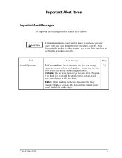
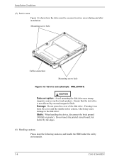
...device, disconnect the body ground (500 kΩ or greater). Also, damage to the disk drive. Ensure that the disk drive is not affected by the edges. Damage: Do not press the cover of the disk drive. C141-E104-03EN v Important Alert Items Important Alert Messages The important alert messages in ... Page Data corruption: Avoid mounting the disk near strong 3-8 magnetic sources such as follows: CAUTION A hazardous situation could result in this manual are as loud speakers. Do not touch the printed circuit board, but hold it too hard, the cover and the spindle motor ...
...device, disconnect the body ground (500 kΩ or greater). Also, damage to the disk drive. Ensure that the disk drive is not affected by the edges. Damage: Do not press the cover of the disk drive. C141-E104-03EN v Important Alert Items Important Alert Messages The important alert messages in ... Page Data corruption: Avoid mounting the disk near strong 3-8 magnetic sources such as follows: CAUTION A hazardous situation could result in this manual are as loud speakers. Do not touch the printed circuit board, but hold it too hard, the cover and the spindle motor ...

Manual/User Guide
Page 22
The MHL Series and MHM Series are 2.5-inch hard disk drives with built-in this chapter, and specifications and power requirement are described. C141-E104-03EN 1-1 CHAPTER 1 Device Overview 1.1 Features 1.2 Device Specifications 1.3 Power Requirements 1.4 Environmental Specifications 1.5 Acoustic Noise 1.6 Shock and Vibration 1.7 Reliability 1.8 Error Rate 1.9 Media Defects Overview and features are described in disk controllers. These disk drives use the AT-bus hard disk interface protocol and are compact and reliable.
The MHL Series and MHM Series are 2.5-inch hard disk drives with built-in this chapter, and specifications and power requirement are described. C141-E104-03EN 1-1 CHAPTER 1 Device Overview 1.1 Features 1.2 Device Specifications 1.3 Power Requirements 1.4 Environmental Specifications 1.5 Acoustic Noise 1.6 Shock and Vibration 1.7 Reliability 1.8 Error Rate 1.9 Media Defects Overview and features are described in disk controllers. These disk drives use the AT-bus hard disk interface protocol and are compact and reliable.
Manual/User Guide
Page 32
C141-E104-03EN 2-1 CHAPTER 2 Device Configuration 2.1 Device Configuration 2.2 System Configuration This chapter describes the internal configurations of the hard disk drives and the configuration of the systems in which they operate.
C141-E104-03EN 2-1 CHAPTER 2 Device Configuration 2.1 Device Configuration 2.2 System Configuration This chapter describes the internal configurations of the hard disk drives and the configuration of the systems in which they operate.
Manual/User Guide
Page 38
C141-E104-03EN 3-1 CHAPTER 3 Installation Conditions 3.1 Dimensions 3.2 Mounting 3.3 Cable Connections 3.4 Jumper Settings This chapter gives the external dimensions, installation conditions, surface temperature conditions, cable connections, and switch settings of the hard disk drives.
C141-E104-03EN 3-1 CHAPTER 3 Installation Conditions 3.1 Dimensions 3.2 Mounting 3.3 Cable Connections 3.4 Jumper Settings This chapter gives the external dimensions, installation conditions, surface temperature conditions, cable connections, and switch settings of the hard disk drives.
Manual/User Guide
Page 45
... 3.6 shows how the drive must be accessed (service areas) during and after installation. Pressing it by external magnetic fields. Do not touch the printed circuit board, but hold it too hard, the cover and the spindle motor contact, which may cause damage to the disk drive. Damage: Do not ...press the cover of the disk drive. Static: When handling the device, disconnect the body ground (500 kΩ or...
... 3.6 shows how the drive must be accessed (service areas) during and after installation. Pressing it by external magnetic fields. Do not touch the printed circuit board, but hold it too hard, the cover and the spindle motor contact, which may cause damage to the disk drive. Damage: Do not ...press the cover of the disk drive. Static: When handling the device, disconnect the body ground (500 kΩ or...
Manual/User Guide
Page 59
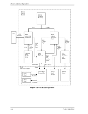
Theory of Device Operation Printed Circuit Board FROM Program Memory 16 bit Local Bus Host ATA Interface HDC (Hard Disk Controller) 16 bit Data Buffer Bus Read and Write Data RDC Control Signal MPU (Micro Processor Unit) HDIC Control Signal SVC Control Signal SDRAM Data Buffer RAM RDC Read Channel Servo Pulse and Position Signal Disk Enclosure Head Read Head Write Data HDIC RReeaaddDDaatata (Read/Write Preamplifier) Read Data Voice Coil Motor Write Head Write Data SVC Motor Controller and Driver Spindle Motor Figure 4.3 Circuit Configuration 4-6 C141-E104-03EN
Theory of Device Operation Printed Circuit Board FROM Program Memory 16 bit Local Bus Host ATA Interface HDC (Hard Disk Controller) 16 bit Data Buffer Bus Read and Write Data RDC Control Signal MPU (Micro Processor Unit) HDIC Control Signal SVC Control Signal SDRAM Data Buffer RAM RDC Read Channel Servo Pulse and Position Signal Disk Enclosure Head Read Head Write Data HDIC RReeaaddDDaatata (Read/Write Preamplifier) Read Data Voice Coil Motor Write Head Write Data SVC Motor Controller and Driver Spindle Motor Figure 4.3 Circuit Configuration 4-6 C141-E104-03EN
Manual/User Guide
Page 64
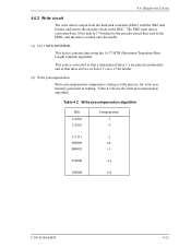
... circuit in a 17-bit border. (2) Write precompensation Write precompensation compensates, during a write process, for write nonlinearity generated at reading. This code is converted from the hard disk controller (HDC) with the NRZ data format, and sent to the HDIC, and the data is written onto the media. (1) 16/17 MTR MEEPRML This...
... circuit in a 17-bit border. (2) Write precompensation Write precompensation compensates, during a write process, for write nonlinearity generated at reading. This code is converted from the hard disk controller (HDC) with the NRZ data format, and sent to the HDIC, and the data is written onto the media. (1) 16/17 MTR MEEPRML This...
Manual/User Guide
Page 215
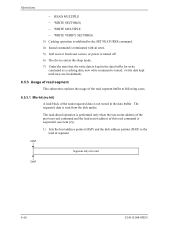
...-03EN The requested data is sequential (see item (2)). 1) Sets the host address pointer (HAP) and the disk address pointer (DAP) to the lead of this read command is read from the disk media. The read-ahead operation is performed only when the last sector address of the previous read command... MULTIPLE − WRITE VERIFY SECTOR(S) 3) Caching operation is inhibited by the SET FEATURES command. 4) Issued command is terminated with an error. 5) Soft reset or hard reset occurs, or power is turned off. 6) The device enters the sleep mode. 7) Under the state that the write data is kept in the data...
...-03EN The requested data is sequential (see item (2)). 1) Sets the host address pointer (HAP) and the disk address pointer (DAP) to the lead of this read command is read from the disk media. The read-ahead operation is performed only when the last sector address of the previous read command... MULTIPLE − WRITE VERIFY SECTOR(S) 3) Caching operation is inhibited by the SET FEATURES command. 4) Issued command is terminated with an error. 5) Soft reset or hard reset occurs, or power is turned off. 6) The device enters the sleep mode. 7) Under the state that the write data is kept in the data...
Manual/User Guide
Page 221
...complete. Operations 3) The cache data for detecting a target sector of the next command is eliminated. The drive receives the next command continuously. This shortens the access time. Even if a hard reset or soft reset is received or the write cache function is disabled by a write command is ... Received data is performed. Cache data Start LBA Last LBA 6.6 Write Cache The write cache function of the previous command. The drive continues writing data on the disk medium. If the received command is a "sequential write" (data to be written by a command is physically sequent to be ...
...complete. Operations 3) The cache data for detecting a target sector of the next command is eliminated. The drive receives the next command continuously. This shortens the access time. Even if a hard reset or soft reset is received or the write cache function is disabled by a write command is ... Received data is performed. Cache data Start LBA Last LBA 6.6 Write Cache The write cache function of the previous command. The drive continues writing data on the disk medium. If the received command is a "sequential write" (data to be written by a command is physically sequent to be ...
Manual/User Guide
Page 228
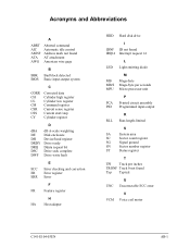
... register D dBA DE DH DRDY DRQ DSC DWF dB A-scale weighting Disk enclosure Device/head register Drive ready Ddata request bit Drive seek complete Drive write fault E ECC Error checking and correction ER Error register ERR Error F FR Feature register H HA Host adapter HDD Hard disk drive IDNF IRQ14 I ID not found Interrupt request 14 L LED Light...
... register D dBA DE DH DRDY DRQ DSC DWF dB A-scale weighting Disk enclosure Device/head register Drive ready Ddata request bit Drive seek complete Drive write fault E ECC Error checking and correction ER Error register ERR Error F FR Feature register H HA Host adapter HDD Hard disk drive IDNF IRQ14 I ID not found Interrupt request 14 L LED Light...


