
Manual/User Guide
Page 23
... 12 ms (at 1 m apart from the drive under the idle mode). 1-2 C141-E104-03EN The disk drive supports an external data rate up to 66.6 MB/s (UDMA mode 4). (4) Average positioning time Use of 30 GB (MHL2300AT), 20 GB (MHM2200AT), 15 GB (MHM2150AT) and 10 GB (MHM2100AT) respectively. (3) High-speed Transfer rate The disk drives (the MHL Series and MHM Series...
... 12 ms (at 1 m apart from the drive under the idle mode). 1-2 C141-E104-03EN The disk drive supports an external data rate up to 66.6 MB/s (UDMA mode 4). (4) Average positioning time Use of 30 GB (MHL2300AT), 20 GB (MHM2200AT), 15 GB (MHM2150AT) and 10 GB (MHM2100AT) respectively. (3) High-speed Transfer rate The disk drives (the MHL Series and MHM Series...

Manual/User Guide
Page 35
... interface system configuration. Figure 2.4 2 drives configuration 2-4 C141-E104-03EN The drive has a 44pin PC AT interface connector and supports PIO mode 4 transfer at 16.6 MB/s, Multiword DMA mode 2 transfer at 16.6 MB/s and also U-DMA mode 4 transfer at 66.6 MB/s. 2.2.2 1 drive connection MHL2300AT MHMC22023020AATT MMHHMC22014500AATT MHM2100AT Figure 2.3 1 drive system configuration 2.2.3 2 drives connection (Host adaptor) MHL2300AT MMHHMC22023020AATT...
... interface system configuration. Figure 2.4 2 drives configuration 2-4 C141-E104-03EN The drive has a 44pin PC AT interface connector and supports PIO mode 4 transfer at 16.6 MB/s, Multiword DMA mode 2 transfer at 16.6 MB/s and also U-DMA mode 4 transfer at 66.6 MB/s. 2.2.2 1 drive connection MHL2300AT MHMC22023020AATT MMHHMC22014500AATT MHM2100AT Figure 2.3 1 drive system configuration 2.2.3 2 drives connection (Host adaptor) MHL2300AT MMHHMC22023020AATT...

Manual/User Guide
Page 83
... device can operate for command execution in either address-specified mode; signals are LBA bits. and CS1- The IDENTIFY DEVICE information indicates whether the device supports the LBA mode. The direction of the Cylinder High, Cylinder Low, and Sector Number registers are not asserted. The device asserts this signal when the...
... device can operate for command execution in either address-specified mode; signals are LBA bits. and CS1- The IDENTIFY DEVICE information indicates whether the device supports the LBA mode. The direction of the Cylinder High, Cylinder Low, and Sector Number registers are not asserted. The device asserts this signal when the...

Manual/User Guide
Page 91
... data transfer) and the host system writes to the command register, the correct device operation is not guaranteed. 5.3.1 Command code and parameters Table 5.3 lists the supported commands, command code and the registers that needed parameters are written.
... data transfer) and the host system writes to the command register, the correct device operation is not guaranteed. 5.3.1 Command code and parameters Table 5.3 lists the supported commands, command code and the registers that needed parameters are written.

Manual/User Guide
Page 110
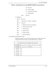
...by READ/WRITE MULTIPLE command *6 Total number of user addressable sectors (LBA mode only) *2 Reserved Multiword DMA transfer mode *7 Advance PIO transfer mode support status *8 Minimum multiword DMA transfer cycle time per track Total number of current sectors Transfer sector count currently set by IDENTIFY DEVICE command (2 of ... PIO transfer cycle time with IORDY flow control : 120 [ns] Reserved Major version number *9 Minor version number (not reported) Support of command sets *10 Support of command sets *11 Support of 8) Word 23-26 27-46 47 48 49 50 51 52 53 54 55 56 57-58 59 60-61...
...by READ/WRITE MULTIPLE command *6 Total number of user addressable sectors (LBA mode only) *2 Reserved Multiword DMA transfer mode *7 Advance PIO transfer mode support status *8 Minimum multiword DMA transfer cycle time per track Total number of current sectors Transfer sector count currently set by IDENTIFY DEVICE command (2 of ... PIO transfer cycle time with IORDY flow control : 120 [ns] Reserved Major version number *9 Minor version number (not reported) Support of command sets *10 Support of command sets *11 Support of 8) Word 23-26 27-46 47 48 49 50 51 52 53 54 55 56 57-58 59 60-61...

Manual/User Guide
Page 112
Bit 12: Reserved Bit 11: IORDY support 1=Supported Bit 10: IORDY inhibition 0=Disable inhibition Bit 9-0: Undefined Bit 9, 8: Always 1 *4 Word 51: PIO data transfer mode Bit 15-8: PIO data transfer mode X'02'=PIO mode... timer value. 5.3 Host Commands Table 5.4 Information to be read by READ/WRITE MULTIPLE command without interrupt supports 2, 4, 8 and 16 sectors. *7 Word 63: Multiword DMA transfer mode Bit 15-8: Currently used multiword DMA transfer mode Bit 7-0: Supportable multiword DMA transfer mode Bit 2=1 Mode 2 Bit 1=1 Mode 1 Bit 0=1 Mode 0 *8 Word 64: Advance PIO ...
Bit 12: Reserved Bit 11: IORDY support 1=Supported Bit 10: IORDY inhibition 0=Disable inhibition Bit 9-0: Undefined Bit 9, 8: Always 1 *4 Word 51: PIO data transfer mode Bit 15-8: PIO data transfer mode X'02'=PIO mode... timer value. 5.3 Host Commands Table 5.4 Information to be read by READ/WRITE MULTIPLE command without interrupt supports 2, 4, 8 and 16 sectors. *7 Word 63: Multiword DMA transfer mode Bit 15-8: Currently used multiword DMA transfer mode Bit 7-0: Supportable multiword DMA transfer mode Bit 2=1 Mode 2 Bit 1=1 Mode 1 Bit 0=1 Mode 0 *8 Word 64: Advance PIO ...

Manual/User Guide
Page 113
... IDENTIFY DEVICE command (5 of 8) Bit 1 = 1 Mode 4 Bit 0 = 1 Mode 3 *9 WORD 80 Bit 15-6: Reserved Bit 5: ATA/ATAPI-5 supported = 1 Bit 4: ATA/ATAPI-4 supported = 1 Bit 3: ATA-3 supported = 1 Bit 2: ATA-2 supported = 1 Bit 1-0: Undefined *10 WORD 82 Bit 15: Undefined Bit 14: '1' = Supports the NOP command. Bit 13: '1' = Supports the READ BUFFER command. Interface Table 5.4 Information to be read cache function.
... IDENTIFY DEVICE command (5 of 8) Bit 1 = 1 Mode 4 Bit 0 = 1 Mode 3 *9 WORD 80 Bit 15-6: Reserved Bit 5: ATA/ATAPI-5 supported = 1 Bit 4: ATA/ATAPI-4 supported = 1 Bit 3: ATA-3 supported = 1 Bit 2: ATA-2 supported = 1 Bit 1-0: Undefined *10 WORD 82 Bit 15: Undefined Bit 14: '1' = Supports the NOP command. Bit 13: '1' = Supports the READ BUFFER command. Interface Table 5.4 Information to be read cache function.

Manual/User Guide
Page 114
...'1' = Enables the P PACKET command set . Bit 5: '1' = Enables the write cache function. Bit 4: '1' = Supports the Removable Media Status Notification feature set . Bit 1: '1' = Supports the READ/WRITE DMA QUEUED command. Bit 13: '1' = Enables the READ BUFFER command. Bit 7: '1' = Enables the ... 10: '1' = Enables the Host Protected Area function. Bit 6: '1' = Enables the read by IDENTIFY DEVICE command (6 of 8) Bit 5: '1' = Supports the Power-Up In Standby set . Bit 3: '1' = Enables the Power Management function. Bit 1: '1' = Enables the Security Mode function. Bit 0: ...
...'1' = Enables the P PACKET command set . Bit 5: '1' = Enables the write cache function. Bit 4: '1' = Supports the Removable Media Status Notification feature set . Bit 1: '1' = Supports the READ/WRITE DMA QUEUED command. Bit 13: '1' = Enables the READ BUFFER command. Bit 7: '1' = Enables the ... 10: '1' = Enables the Host Protected Area function. Bit 6: '1' = Enables the read by IDENTIFY DEVICE command (6 of 8) Bit 5: '1' = Supports the Power-Up In Standby set . Bit 3: '1' = Enables the Power Management function. Bit 1: '1' = Enables the Security Mode function. Bit 0: ...

Manual/User Guide
Page 115
... selfdiagnosis. Bits 12-8: In the case of 8) Bits 2-0: Same definition as WORD 83. *14 WORD 88 Bit 15-8: Currently used Ultra DMA transfer mode Bit 7-0: Supportable Ultra DMA transfer mode Bit 4 = '1': Mode 4 Bit 3 = '1': Mode 3 Bit 2 = '1': Mode 2 Bit 1 = '1': Mode 1 Bit 0 = '1': Mode 0 *15 WORD 93 Bits 15-14: Reserved Bit 13: ... Bit 11: '1' = Device asserts PDIAG-. of PDIAG- is set . Interface Table 5.4 Information to be read by IDENTIFY DEVICE command (7 of Device 1 (slave drive), a valid value is a level lower than VIH. '0' = CBLID- is selected, Device 0 responds.
... selfdiagnosis. Bits 12-8: In the case of 8) Bits 2-0: Same definition as WORD 83. *14 WORD 88 Bit 15-8: Currently used Ultra DMA transfer mode Bit 7-0: Supportable Ultra DMA transfer mode Bit 4 = '1': Mode 4 Bit 3 = '1': Mode 3 Bit 2 = '1': Mode 2 Bit 1 = '1': Mode 1 Bit 0 = '1': Mode 0 *15 WORD 93 Bits 15-14: Reserved Bit 13: ... Bit 11: '1' = Device asserts PDIAG-. of PDIAG- is set . Interface Table 5.4 Information to be read by IDENTIFY DEVICE command (7 of Device 1 (slave drive), a valid value is a level lower than VIH. '0' = CBLID- is selected, Device 0 responds.
Manual/User Guide
Page 116
... *16 WORD 128 Bit 15-9: Reserved Bit 8: Security level. 0: High, 1: Maximum Bit 7-6: Reserved Bit 5: 1: Enhanced security erase supported Bit 4: 1: Security counter expired Bit 3: 1: Security frozen Bit 2: 1: Security locked Bit 1: 1: Security enabled Bit 0: 1: Security supported (13) IDENTIFY DEVICE DMA (X'EE') When this command functions in DMA mode, this command is not used to...
... *16 WORD 128 Bit 15-9: Reserved Bit 8: Security level. 0: High, 1: Maximum Bit 7-6: Reserved Bit 5: 1: Enhanced security erase supported Bit 4: 1: Security counter expired Bit 3: 1: Security frozen Bit 2: 1: Security locked Bit 1: 1: Security enabled Bit 0: 1: Security supported (13) IDENTIFY DEVICE DMA (X'EE') When this command functions in DMA mode, this command is not used to...
Manual/User Guide
Page 117
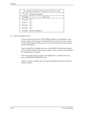
... can be set parameters in the Features register for the purpose of the Status register and saves the parameters in the Features register is not supported or it is invalid, the device posts an ABORTED COMMAND error. Interface At command completion (I/O registers contents to be read) 1F7H(ST) 1F6H(DH) 1F5H...
... can be set parameters in the Features register for the purpose of the Status register and saves the parameters in the Features register is not supported or it is invalid, the device posts an ABORTED COMMAND error. Interface At command completion (I/O registers contents to be read) 1F7H(ST) 1F6H(DH) 1F5H...
Manual/User Guide
Page 119
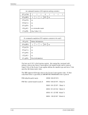
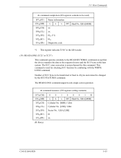
...) xx 1F3H(SN) xx 1F2H(SC) xx or transfer mode 1F1H(FR) [See Table 5.5] At command completion (I/O registers contents to the Features register. The IDD supports following values in the Sector Count register value. PIO default transfer mode 00000 000 (X'00') PIO flow control transfer mode X 00001 000 (X'08': Mode 0) 00001...
...) xx 1F3H(SN) xx 1F2H(SC) xx or transfer mode 1F1H(FR) [See Table 5.5] At command completion (I/O registers contents to the Features register. The IDD supports following values in the Sector Count register value. PIO default transfer mode 00000 000 (X'00') PIO flow control transfer mode X 00001 000 (X'08': Mode 0) 00001...

Manual/User Guide
Page 120
...register X'05', and then Advanced Power Management is then enabled. If the contents of the Sector Count register is valid and is a supported block count, the value is stored for these commands is enabled. When the SET MULTIPLE MODE command operation is written into the Sector... the SET MULTIPLE MODE command is posted and the READ MULTIPLE and WRITE MULTIPLE commands are disabled. 5.3 Host Commands Multiword DMA transfer mode X 00100 000 (X'20': Mode 0) 00100 001 (X'21': Mode 1) 00100 010 (X'22': Mode 2) Ultra DMA transfer mode X 01000 000 (X'40': Mode 0) 01000 001 (X'41': Mode...
...register X'05', and then Advanced Power Management is then enabled. If the contents of the Sector Count register is valid and is a supported block count, the value is stored for these commands is enabled. When the SET MULTIPLE MODE command operation is written into the Sector... the SET MULTIPLE MODE command is posted and the READ MULTIPLE and WRITE MULTIPLE commands are disabled. 5.3 Host Commands Multiword DMA transfer mode X 00100 000 (X'20': Mode 0) 00100 001 (X'21': Mode 1) 00100 010 (X'22': Mode 2) Ultra DMA transfer mode X 01000 000 (X'40': Mode 0) 01000 001 (X'41': Mode...
Manual/User Guide
Page 130
The READ LONG command supports only single sector operation. The ECC error correction is used for this command. Number of ECC bytes to be transferred is fixed to 4 bytes and ...
The READ LONG command supports only single sector operation. The ECC error correction is used for this command. Number of ECC bytes to be transferred is fixed to 4 bytes and ...
Manual/User Guide
Page 131
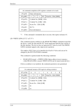
...] / LBA Cylinder No. [LSB] / LBA Sector No. / LBA [LSB] 00 (*1) Error information *1 If the command is terminated due to an error, this register indicates 01. (20) WRITE LONG (X'32' or X'33') This command operates similarly to the READ SECTOR(S) command except that the device writes the data and the ECC bytes... command operation is issued, WRITE LONG can not be changed by itself. At command issuance (I /O registers contents to the disk medium. The WRITE LONG command supports only single sector operation. The device does not generate ECC bytes by the SET FEATURES command.
...] / LBA Cylinder No. [LSB] / LBA Sector No. / LBA [LSB] 00 (*1) Error information *1 If the command is terminated due to an error, this register indicates 01. (20) WRITE LONG (X'32' or X'33') This command operates similarly to the READ SECTOR(S) command except that the device writes the data and the ECC bytes... command operation is issued, WRITE LONG can not be changed by itself. At command issuance (I /O registers contents to the disk medium. The WRITE LONG command supports only single sector operation. The device does not generate ECC bytes by the SET FEATURES command.
Manual/User Guide
Page 135
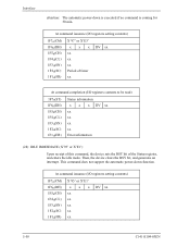
Interface attention: The automatic power-down function. Then, the device clears the BSY bit, and generates an interrupt. This command does not support the automatic power-down is executed if no command is coming for 30 min. At command issuance (I/O registers setting contents) 1F7H(CM) 1F6H(DH) 1F5H(...
Interface attention: The automatic power-down function. Then, the device clears the BSY bit, and generates an interrupt. This command does not support the automatic power-down is executed if no command is coming for 30 min. At command issuance (I/O registers setting contents) 1F7H(CM) 1F6H(DH) 1F5H(...
Manual/User Guide
Page 137
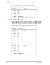
... xx xx xx xx Error information 5-60 C141-E104-03EN The device then clears the BSY bit and generates an interrupt. This command does not support the automatic power-down sequence.
... xx xx xx xx Error information 5-60 C141-E104-03EN The device then clears the BSY bit and generates an interrupt. This command does not support the automatic power-down sequence.
Manual/User Guide
Page 140
... of items collected or updated by the device to forecast failures are set the keys (CL = 4Fh and CH = C2h) in the FR register is supported, the Aborted Command error is posted. C141-E104-03EN 5-63 If the value specified in the CL and CH registers prior to as attribute values...
... of items collected or updated by the device to forecast failures are set the keys (CL = 4Fh and CH = C2h) in the FR register is supported, the Aborted Command error is posted. C141-E104-03EN 5-63 If the value specified in the CL and CH registers prior to as attribute values...

Manual/User Guide
Page 148
... to a media after the previously set operation. Self-test has been aborted by an unknown meaning. Self-test has been completed abnormally by the drive. If the off-line data collection capability is in progress. • Off-line data collection capability Indicates the method of off-line data collection ...suspended by serbo test. Self-test has been completed abnormally by hard or soft reset. Self-test has been completed abnormally by the host computer. Bit Meaning 0 Indicates that Execute Off-Line Immediate is supported. 1 Vendor unique 2 Indicates that off-line data collection ...
... to a media after the previously set operation. Self-test has been aborted by an unknown meaning. Self-test has been completed abnormally by the drive. If the off-line data collection capability is in progress. • Off-line data collection capability Indicates the method of off-line data collection ...suspended by serbo test. Self-test has been completed abnormally by hard or soft reset. Self-test has been completed abnormally by the host computer. Bit Meaning 0 Indicates that Execute Off-Line Immediate is supported. 1 Vendor unique 2 Indicates that off-line data collection ...

Manual/User Guide
Page 169
... during an Ultra DMA burst. DMARQ and DMACK- The Ultra DMA Mode selected by the host at the termination of supporting. Devices supporting Ultra DMA Mode 2 shall also support Ultra DMA Modes 0 and 1. An Ultra DMA capable device shall retain its default nonUltra DMA Modes after executing a... DMA Mode 1 shall also support Ultra DMA Mode 0. Interface 5.5 Ultra DMA Feature Set 5.5.1 Overview Ultra DMA is a data transfer protocol used for data transfers so that drives the data onto the bus. Several signal lines are unidirectional. Both edges of STROBE are given either host or ...
... during an Ultra DMA burst. DMARQ and DMACK- The Ultra DMA Mode selected by the host at the termination of supporting. Devices supporting Ultra DMA Mode 2 shall also support Ultra DMA Modes 0 and 1. An Ultra DMA capable device shall retain its default nonUltra DMA Modes after executing a... DMA Mode 1 shall also support Ultra DMA Mode 0. Interface 5.5 Ultra DMA Feature Set 5.5.1 Overview Ultra DMA is a data transfer protocol used for data transfers so that drives the data onto the bus. Several signal lines are unidirectional. Both edges of STROBE are given either host or ...