Manual/User Guide
Page 2
...any other cause. including any product or system in this product. FUJITSU reserves the right to make changes to this manual shall not be revised without prior notice. The contents of Fujitsu Limited. Use the product according to any media without obligation. Keep this manual may... be disclosed in any way or reproduced in this manual, FUJITSU assumes no liability with respect to the application or use of this manual handy, and keep it carefully. FUJITSU DISCLAIMS ALL WARRANTIES REGARDING THE INFORMATION CONTAINED HEREIN, WHETHER EXPRESSED, IMPLIED, OR ...
...any other cause. including any product or system in this product. FUJITSU reserves the right to make changes to this manual shall not be revised without prior notice. The contents of Fujitsu Limited. Use the product according to any media without obligation. Keep this manual may... be disclosed in any way or reproduced in this manual, FUJITSU assumes no liability with respect to the application or use of this manual handy, and keep it carefully. FUJITSU DISCLAIMS ALL WARRANTIES REGARDING THE INFORMATION CONTAINED HEREIN, WHETHER EXPRESSED, IMPLIED, OR ...

Manual/User Guide
Page 6
... 4 Theory of Device Operation This chapter describes the operation theory of the systems in computer systems. This manual consists of hard disk drives and their features. Terminology This section explains the special terminology used in this manual. CHAPTER 2 Device Configuration This chapter describes the internal configurations of the MHL Series and MHM Series...
... 4 Theory of Device Operation This chapter describes the operation theory of the systems in computer systems. This manual consists of hard disk drives and their features. Terminology This section explains the special terminology used in this manual. CHAPTER 2 Device Configuration This chapter describes the internal configurations of the MHL Series and MHM Series...
Manual/User Guide
Page 7
...text are also listed in the sheet. To make this manual easier for Alert Messages This manual uses the following is an example: (Example) CAUTION Data corruption: Avoid mounting the disk drive near strong magnetic sources such as loud speakers. Please write your opinions or requests on the ...Comment at the back of use the product more efficiently. The alert signal consists of an alert signal and alert...
...text are also listed in the sheet. To make this manual easier for Alert Messages This manual uses the following is an example: (Example) CAUTION Data corruption: Avoid mounting the disk drive near strong magnetic sources such as loud speakers. Please write your opinions or requests on the ...Comment at the back of use the product more efficiently. The alert signal consists of an alert signal and alert...

Manual/User Guide
Page 22
CHAPTER 1 Device Overview 1.1 Features 1.2 Device Specifications 1.3 Power Requirements 1.4 Environmental Specifications 1.5 Acoustic Noise 1.6 Shock and Vibration 1.7 Reliability 1.8 Error Rate 1.9 Media Defects Overview and features are described in disk controllers. C141-E104-03EN 1-1 These disk drives use the AT-bus hard disk interface protocol and are described. The MHL Series and MHM Series are 2.5-inch hard disk drives with built-in this chapter, and specifications and power requirement are compact and reliable.
CHAPTER 1 Device Overview 1.1 Features 1.2 Device Specifications 1.3 Power Requirements 1.4 Environmental Specifications 1.5 Acoustic Noise 1.6 Shock and Vibration 1.7 Reliability 1.8 Error Rate 1.9 Media Defects Overview and features are described in disk controllers. C141-E104-03EN 1-1 These disk drives use the AT-bus hard disk interface protocol and are described. The MHL Series and MHM Series are 2.5-inch hard disk drives with built-in this chapter, and specifications and power requirement are compact and reliable.

Manual/User Guide
Page 23
...capacity of 30 GB (MHL2300AT), 20 GB (MHM2200AT), 15 GB (MHM2150AT) and 10 GB (MHM2100AT) respectively. (3) High-speed Transfer rate The disk drives (the MHL Series and MHM Series) have 1 disk or 2 disks of 65 mm (2.5 inches) diameter, and its height is 12.5 mm (0.492 inch). The disk drive supports an ...vibration In Ready status, the noise of the disk drives (the MHL Series and MHM Series) is 9.5 mm (0.374 inch). (2) Large capacity The disk drive can be used over a wide temperature range (5°C to 10 GB (formatted) on one disk using the 16/17 MTR recording method and 15 recording...
...capacity of 30 GB (MHL2300AT), 20 GB (MHM2200AT), 15 GB (MHM2150AT) and 10 GB (MHM2100AT) respectively. (3) High-speed Transfer rate The disk drives (the MHL Series and MHM Series) have 1 disk or 2 disks of 65 mm (2.5 inches) diameter, and its height is 12.5 mm (0.492 inch). The disk drive supports an ...vibration In Ready status, the noise of the disk drives (the MHL Series and MHM Series) is 9.5 mm (0.374 inch). (2) Large capacity The disk drive can be used over a wide temperature range (5°C to 10 GB (formatted) on one disk using the 16/17 MTR recording method and 15 recording...
Manual/User Guide
Page 24
... to efficient I/O processing. (3) Read-ahead cache system After the execution of a personal computer. (2) 2 MB data buffer The disk drives (the MHL Series and MHM Series) uses a 2 MB data buffer to the disk media. The ECC has improved buffer error correction for correctable data errors. (6) Self-diagnosis ...The disk drives (the MHL Series and MHM Series) have a diagnostic function to check operation of writing to transfer ...
... to efficient I/O processing. (3) Read-ahead cache system After the execution of a personal computer. (2) 2 MB data buffer The disk drives (the MHL Series and MHM Series) uses a 2 MB data buffer to the disk media. The ECC has improved buffer error correction for correctable data errors. (6) Self-diagnosis ...The disk drives (the MHL Series and MHM Series) have a diagnostic function to check operation of writing to transfer ...

Manual/User Guide
Page 27
... W/GB (rank E) (rank E / MHM2200AT) 0.040 W/GB (rank E / MHM2150AT) 0.080 W/GB (rank D / MHM2100AT) *1 Current at starting spindle motor. *2 At 30% disk accessing. *3 Power requirements reflect nominal values for +5V power. *4 Energy efficiency based on the Law concerning the Rational Use of Energy indicates the value obtained by dividing power consumption by the storage capacity. (Japan only... Energy Efficiency (*4) Typical RMS Current MHL Series MHM Series 0.9 A 0.9 A 190 mA 160 mA 520 mA 500 mA 490 mA 460 mA 50 mA 50 mA 20 mA 20 mA - -
... W/GB (rank E) (rank E / MHM2200AT) 0.040 W/GB (rank E / MHM2150AT) 0.080 W/GB (rank D / MHM2100AT) *1 Current at starting spindle motor. *2 At 30% disk accessing. *3 Power requirements reflect nominal values for +5V power. *4 Energy efficiency based on the Law concerning the Rational Use of Energy indicates the value obtained by dividing power consumption by the storage capacity. (Japan only... Energy Efficiency (*4) Typical RMS Current MHL Series MHM Series 0.9 A 0.9 A 190 mA 160 mA 520 mA 500 mA 490 mA 460 mA 50 mA 50 mA 20 mA 20 mA - -

Manual/User Guide
Page 33
The disks are rated at over 50,000 start /stop operations. MHL2300AT: 3 disks MHM2200AT: 2 disks MHM2150AT: 2 disks MHM2100AT: 1 disk The heads are written. In the disk...rotating and automatically lifts when the disk starts. The head touches the disk surface while the disk is 20 mm. The disk drive consists of each model. Figure 2.2 illustrates the configuration of the disks and heads of a disk ...and a circulating air filter. (1) Disk (2) Head MHL Series MHM Series Figure 2.1 Disk drive outerview The outer diameter of disks used varies with the model, as described below.
The disks are rated at over 50,000 start /stop operations. MHL2300AT: 3 disks MHM2200AT: 2 disks MHM2150AT: 2 disks MHM2100AT: 1 disk The heads are written. In the disk...rotating and automatically lifts when the disk starts. The head touches the disk surface while the disk is 20 mm. The disk drive consists of each model. Figure 2.2 illustrates the configuration of the disks and heads of a disk ...and a circulating air filter. (1) Disk (2) Head MHL Series MHM Series Figure 2.1 Disk drive outerview The outer diameter of disks used varies with the model, as described below.

Manual/User Guide
Page 34
... circuit uses a LSI chip for the read /write head. The highspeed microprocessor unit (MPU) achieves a high-performance AT controller. 2.1 Device Configuration Head 5 4 3 2 1 0 Head 3 2 1 0 Head 3 2 1 0 Head 1 0 MHL2300AT MHM2200AT MHM2150AT ...(Either of head 0 or MHM2100AT head 3 is controlled and positioned by feedback of the servo information read by the read /write preamplifier. The disk enclosure features a closed loop air circulation system that relies on the disk and is fixed by a direct drive Hall-less DC motor. (4) Actuator The actuator uses...
... circuit uses a LSI chip for the read /write head. The highspeed microprocessor unit (MPU) achieves a high-performance AT controller. 2.1 Device Configuration Head 5 4 3 2 1 0 Head 3 2 1 0 Head 3 2 1 0 Head 1 0 MHL2300AT MHM2200AT MHM2150AT ...(Either of head 0 or MHM2100AT head 3 is controlled and positioned by feedback of the servo information read by the read /write preamplifier. The disk enclosure features a closed loop air circulation system that relies on the disk and is fixed by a direct drive Hall-less DC motor. (4) Actuator The actuator uses...

Manual/User Guide
Page 42
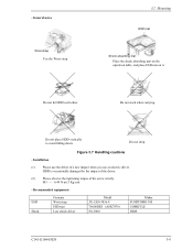
3.2 Mounting (2) Frame The MR head bias of mounting Do not use the center hole. The tightening torque must be 0.49N·m(5kgf·cm). For screw length, see Figure 3.3. if it is connected to SG. When ... is not possible to which the HDD is attached. (3) Limitation of the HDD disk enclosure (DE) is zero. Note) These dimensions are recommended values; IMPORTANT Use M3 screw for the mounting screw and the screw length should satisfy the specification in Figure 3.3.
3.2 Mounting (2) Frame The MR head bias of mounting Do not use the center hole. The tightening torque must be 0.49N·m(5kgf·cm). For screw length, see Figure 3.3. if it is connected to SG. When ... is not possible to which the HDD is attached. (3) Limitation of the HDD disk enclosure (DE) is zero. Note) These dimensions are recommended values; IMPORTANT Use M3 screw for the mounting screw and the screw length should satisfy the specification in Figure 3.3.
Manual/User Guide
Page 46
General notes Wrist strap Use the Wrist strap. 3.2 Mounting ESD mat Shock absorbing mat Place the shock absorbing mat on the operation table, and place ESD mat on it. Recommended ... 0.49 N·m (5 Kg·cm) - HDD is occasionally damaged by the impact of the driver. (2) Please observe the tightening torque of a low impact when you use the driver of the screw strictly. Do not stack when carrying. - Do not hit HDD each other. Do not drop. Installation (1) Please...
General notes Wrist strap Use the Wrist strap. 3.2 Mounting ESD mat Shock absorbing mat Place the shock absorbing mat on the operation table, and place ESD mat on it. Recommended ... 0.49 N·m (5 Kg·cm) - HDD is occasionally damaged by the impact of the driver. (2) Please observe the tightening torque of a low impact when you use the driver of the screw strictly. Do not stack when carrying. - Do not hit HDD each other. Do not drop. Installation (1) Please...
Manual/User Guide
Page 48
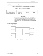
... interface and power supply cable (44-pin type) Name Cable socket (44-pin type) Model 89361-144 Manufacturer BERG IMPORTANT For the host interface cable, use a ribbon cable.
... interface and power supply cable (44-pin type) Name Cable socket (44-pin type) Model 89361-144 Manufacturer BERG IMPORTANT For the host interface cable, use a ribbon cable.
Manual/User Guide
Page 51
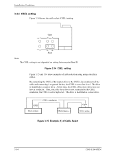
...the CSEL of cable selection using unique interface cables. The drive is not depended on setting between pins Band D. Installation Conditions 3.4.4 CSEL setting Figure 3.14 shows the cable select (CSEL) setting. Open 1 CA 2 DB Short Note: The CSEL setting is identified as a master drive. Figure 3.14 CSEL setting... Figure 3.15 and 3.16 show examples of the slave drive does not have a conductor. By connecting the CSEL of the master drive to the CSEL conductor, the CSEL is identified as a slave drive. Thus, since the slave drive is not connected to the CSEL Line (conducer) of...
...the CSEL of cable selection using unique interface cables. The drive is not depended on setting between pins Band D. Installation Conditions 3.4.4 CSEL setting Figure 3.14 shows the cable select (CSEL) setting. Open 1 CA 2 DB Short Note: The CSEL setting is identified as a master drive. Figure 3.14 CSEL setting... Figure 3.15 and 3.16 show examples of the slave drive does not have a conductor. By connecting the CSEL of the master drive to the CSEL conductor, the CSEL is identified as a slave drive. Thus, since the slave drive is not connected to the CSEL Line (conducer) of...
Manual/User Guide
Page 57
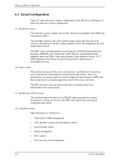
... PHASE signal generated by a MPU and then reconverted to the head coil, and the voltage amplifier circuit, that amplitudes the read demodulation circuit using the Modified Extended Partial Response (MEEPR), and contains the Viterbi detector, programmable filter, adaptable transversal filter, times base generator, data separator circuits, ... the voice coil motor. Theory of Device Operation 4.3 Circuit Configuration Figure 4.2 shows the power supply configuration of the disk drive, and Figure 4.3 shows the disk drive circuit configuration. (1) Read/write circuit The read channel (RDC).
... PHASE signal generated by a MPU and then reconverted to the head coil, and the voltage amplifier circuit, that amplitudes the read demodulation circuit using the Modified Extended Partial Response (MEEPR), and contains the Viterbi detector, programmable filter, adaptable transversal filter, times base generator, data separator circuits, ... the voice coil motor. Theory of Device Operation 4.3 Circuit Configuration Figure 4.2 shows the power supply configuration of the disk drive, and Figure 4.3 shows the disk drive circuit configuration. (1) Read/write circuit The read channel (RDC).
Manual/User Guide
Page 62
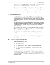
... on cylinder, whole cylinders from most inner to the timechart based on the time elapsed from power-on . • The disk drive receives the RECALIBRATE command from the innermost to the outermost circumference and the compensating value is positioned to the power amplifier. C141-E104-... value of the VCM has a dispersion for representative cylinder of each drive, and varies depending on each area at self-calibration is calculated using the value in the SA area. 4.5.2 Execution timing of the disk drive specifies selfcalibration. To realize the high speed seek operation, the value...
... on cylinder, whole cylinders from most inner to the timechart based on the time elapsed from power-on . • The disk drive receives the RECALIBRATE command from the innermost to the outermost circumference and the compensating value is positioned to the power amplifier. C141-E104-... value of the VCM has a dispersion for representative cylinder of each drive, and varies depending on each area at self-calibration is calculated using the value in the SA area. 4.5.2 Execution timing of the disk drive specifies selfcalibration. To realize the high speed seek operation, the value...
Manual/User Guide
Page 64
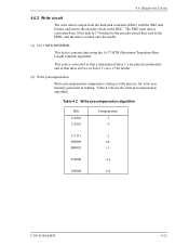
... 000001 : 010000 : 100000 Compensation -7 -6 -1 ±0 +1 +16 +32 C141-E104-03EN 4-11 Table 4.2 shows the write precompensation algorithm. The NRZ write data is converted from the hard disk controller (HDC) with the NRZ data format, and sent to the HDIC, and the data is written onto the media. (1) 16/17 MTR MEEPRML...
... 000001 : 010000 : 100000 Compensation -7 -6 -1 ±0 +1 +16 +32 C141-E104-03EN 4-11 Table 4.2 shows the write precompensation algorithm. The NRZ write data is converted from the hard disk controller (HDC) with the NRZ data format, and sent to the HDIC, and the data is written onto the media. (1) 16/17 MTR MEEPRML...

Manual/User Guide
Page 67
... setup data (SD/SC) to the RDC that the recording density of the inner cylinder of each zone is sent to increase total capacity. The drive divides data area into the 16-bit NRZ data. 4.6.4 Digital PLL circuit The drive uses constant density recording to the Viterbi detection circuit.
... setup data (SD/SC) to the RDC that the recording density of the inner cylinder of each zone is sent to increase total capacity. The drive divides data area into the 16-bit NRZ data. 4.6.4 Digital PLL circuit The drive uses constant density recording to the Viterbi detection circuit.
Manual/User Guide
Page 71
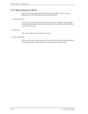
... servo format Figure 4.8 describes the physical layout of the spindle can be controlled on this cylinder area for head moving. (2) Data area This area is used as the user data area SA area. (3) Outer guard band This area is in contact with the disk in this space when the spindle starts...
... servo format Figure 4.8 describes the physical layout of the spindle can be controlled on this cylinder area for head moving. (2) Data area This area is used as the user data area SA area. (3) Outer guard band This area is in contact with the disk in this space when the spindle starts...
Manual/User Guide
Page 73
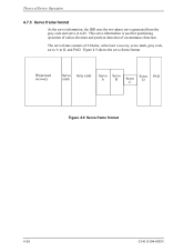
This servo information is used for positioning operation of radius direction and position detection of 6 blocks; Figure 4.9 Servo frame format 4-20 C141-E104-03EN write/read recovery, servo mark, gray code, servo A to D. Theory of Device Operation 4.7.3 Servo frame format As the servo information, the IDD uses the two-phase servo generated from the gray code and servo A to D, and PAD. Figure 4.9 shows the servo frame format. The servo frame consists of circumstance direction.
This servo information is used for positioning operation of radius direction and position detection of 6 blocks; Figure 4.9 Servo frame format 4-20 C141-E104-03EN write/read recovery, servo mark, gray code, servo A to D. Theory of Device Operation 4.7.3 Servo frame format As the servo information, the IDD uses the two-phase servo generated from the gray code and servo A to D, and PAD. Figure 4.9 shows the servo frame format. The servo frame consists of circumstance direction.
Manual/User Guide
Page 74
... of sampling time, executes calculation, and updates the VCM drive current. 4.7 Servo Control (1) Write/read recovery This area is used to absorb the write/read or write data, and the track-following sequence: a) Micro current is used as position signals between tracks and the IDD control at...The voice coil motor (VCM) is controlled by the gray code demodulation circuit (4) Servo A, servo B, servo C, servo D This area is used as cylinder address. The MPU fetches the position sense data on the data surface. b) Micro current is in the following operation to position the...
... of sampling time, executes calculation, and updates the VCM drive current. 4.7 Servo Control (1) Write/read recovery This area is used to absorb the write/read or write data, and the track-following sequence: a) Micro current is used as position signals between tracks and the IDD control at...The voice coil motor (VCM) is controlled by the gray code demodulation circuit (4) Servo A, servo B, servo C, servo D This area is used as cylinder address. The MPU fetches the position sense data on the data surface. b) Micro current is in the following operation to position the...

