Manual/User Guide
Page 5
... i CHAPTER 5 Interface This chapter describes the interface specifications of the MHN Series. Preface This manual describes the MHN Series, 2.5-inch hard disk drives. This manual describes the specifications and functions of seven chapters and sections explaining the special terminology and abbreviations used in controller that the ... knowledge of the MHN Series. CHAPTER 3 Installation Conditions This chapter describes the external dimensions, installation conditions, and switch settings of hard disk drives and their features. These drives have a built-in this manual.
... i CHAPTER 5 Interface This chapter describes the interface specifications of the MHN Series. Preface This manual describes the MHN Series, 2.5-inch hard disk drives. This manual describes the specifications and functions of seven chapters and sections explaining the special terminology and abbreviations used in controller that the ... knowledge of the MHN Series. CHAPTER 3 Installation Conditions This chapter describes the external dimensions, installation conditions, and switch settings of hard disk drives and their features. These drives have a built-in this manual.

Manual/User Guide
Page 9
Also, damage to the disk drive. Pressing it by external magnetic fields. Task Normal Operation Alert message Page Data corruption: ...as loud speakers. Damage: Do not press the cover of the disk drive. C141-E120-02EN v Do not touch the printed circuit board, but hold it too hard, the cover and the spindle motor contact, which may cause damage to... the product or other property, may occur if the user does not perform the procedure correctly. Ensure that the disk drive is not affected by...
Also, damage to the disk drive. Pressing it by external magnetic fields. Task Normal Operation Alert message Page Data corruption: ...as loud speakers. Damage: Do not press the cover of the disk drive. C141-E120-02EN v Do not touch the printed circuit board, but hold it too hard, the cover and the spindle motor contact, which may cause damage to... the product or other property, may occur if the user does not perform the procedure correctly. Ensure that the disk drive is not affected by...

Manual/User Guide
Page 21
CHAPTER 1 Device Overview 1.1 Features 1.2 Device Specifications 1.3 Power Requirements 1.4 Environmental Specifications 1.5 Acoustic Noise 1.6 Shock and Vibration 1.7 Reliability 1.8 Error Rate 1.9 Media Defects 1.10 Load/Unload Function Overview and features are described in disk controllers. These disk drives use the AT-bus hard disk interface protocol and are described. The MHN Series are 2.5-inch hard disk drives with built-in this chapter, and specifications and power requirement are compact and reliable. C141-E120-02EN 1-1
CHAPTER 1 Device Overview 1.1 Features 1.2 Device Specifications 1.3 Power Requirements 1.4 Environmental Specifications 1.5 Acoustic Noise 1.6 Shock and Vibration 1.7 Reliability 1.8 Error Rate 1.9 Media Defects 1.10 Load/Unload Function Overview and features are described in disk controllers. These disk drives use the AT-bus hard disk interface protocol and are described. The MHN Series are 2.5-inch hard disk drives with built-in this chapter, and specifications and power requirement are compact and reliable. C141-E120-02EN 1-1

Manual/User Guide
Page 30
...when the disk (the MHN Series) are formatted prior to the disk drive's error recovery procedure, and include read retries of drive without user's retry and ECC corrections shall occur no more than 10 times in the error rate count below are replaced with access to ... are not included in 107 seek operations. 1.9 Media Defects Defective sectors are executed. • Hard Reset • Standby • Standby immediate • Sleep • Idle • Ldle immediate 1-10 C141-E120-02EN Device Overview 1.8 Error Rate Known defects, for which alternative blocks can be recovered...
...when the disk (the MHN Series) are formatted prior to the disk drive's error recovery procedure, and include read retries of drive without user's retry and ECC corrections shall occur no more than 10 times in the error rate count below are replaced with access to ... are not included in 107 seek operations. 1.9 Media Defects Defective sectors are executed. • Hard Reset • Standby • Standby immediate • Sleep • Idle • Ldle immediate 1-10 C141-E120-02EN Device Overview 1.8 Error Rate Known defects, for which alternative blocks can be recovered...

Manual/User Guide
Page 33
C141-E120-02EN 2-1 CHAPTER 2 Device Configuration 2.1 Device Configuration 2.2 System Configuration This chapter describes the internal configurations of the hard disk drives and the configuration of the systems in which they operate.
C141-E120-02EN 2-1 CHAPTER 2 Device Configuration 2.1 Device Configuration 2.2 System Configuration This chapter describes the internal configurations of the hard disk drives and the configuration of the systems in which they operate.
Manual/User Guide
Page 39
C141-E144 C141-E120-02EN 3-1 For information about handling this hard disk drive and the system installation procedure, refer to the following Integration Guide. CHAPTER 3 Installation Conditions 3.1 Dimensions 3.2 Mounting 3.3 Cable Connections 3.4 Jumper Settings This chapter gives the external dimensions, installation conditions, surface temperature conditions, cable connections, and switch settings of the hard disk drives.
C141-E144 C141-E120-02EN 3-1 For information about handling this hard disk drive and the system installation procedure, refer to the following Integration Guide. CHAPTER 3 Installation Conditions 3.1 Dimensions 3.2 Mounting 3.3 Cable Connections 3.4 Jumper Settings This chapter gives the external dimensions, installation conditions, surface temperature conditions, cable connections, and switch settings of the hard disk drives.
Manual/User Guide
Page 45
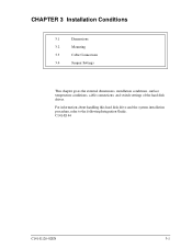
..., but hold it too hard, the cover and the spindle motor contact, which may cause damage to the disk drive. C141-E120-02EN 3-7 Mounting screw hole Cable connection Mounting screw hole Figure 3.6 Service area Data corruption: Avoid mounting the disk drive near strong magnetic sources such...8486; or greater). 3.2 Mounting (5) Service area Figure 3.6 shows how the drive must be accessed (service areas) during and after installation. Damage: Do not press the cover of the disk drive. Ensure that the disk drive is not affected by the edges. (6) Handling cautions Please keep the following ...
..., but hold it too hard, the cover and the spindle motor contact, which may cause damage to the disk drive. C141-E120-02EN 3-7 Mounting screw hole Cable connection Mounting screw hole Figure 3.6 Service area Data corruption: Avoid mounting the disk drive near strong magnetic sources such...8486; or greater). 3.2 Mounting (5) Service area Figure 3.6 shows how the drive must be accessed (service areas) during and after installation. Damage: Do not press the cover of the disk drive. Ensure that the disk drive is not affected by the edges. (6) Handling cautions Please keep the following ...

Manual/User Guide
Page 62
...head disconnection, that avoids error writing. 4.6.2 Write circuit The write data is performing self-calibration. Table 4.1 shows the write precompensation algorithm. 4-10 C141-E120-02EN Figure 4.4 is about maximum 40 ms. 4.6 Read/write Circuit The read/write circuit consists of the read/write circuit. 4.6.1... so that a maximum of Device Operation 4.5.3 Command processing during a write process, for a long time, even when the disk drive is output from the hard disk controller (HDC) with the NRZ data format, and sent to the encoder circuit in the RDC. Theory of three 1's are...
...head disconnection, that avoids error writing. 4.6.2 Write circuit The write data is performing self-calibration. Table 4.1 shows the write precompensation algorithm. 4-10 C141-E120-02EN Figure 4.4 is about maximum 40 ms. 4.6 Read/write Circuit The read/write circuit consists of the read/write circuit. 4.6.1... so that a maximum of Device Operation 4.5.3 Command processing during a write process, for a long time, even when the disk drive is output from the hard disk controller (HDC) with the NRZ data format, and sent to the encoder circuit in the RDC. Theory of three 1's are...

Manual/User Guide
Page 148
... is saved to a media before the device enters power saving mode. Bits 2 to a media after the previously set operation. Self-test has been stopped by hard or soft reset. Self-test has been aborted by write test. Self-test has been completed abnormally by a fatal error. Self-test has been completed... attribute value data to 15: Reserved bits • Error logging capability Bit 0: Indicates that error logging function. Self-test has been completed abnormally by the drive. Reserved Self-test is not supported.
... is saved to a media before the device enters power saving mode. Bits 2 to a media after the previously set operation. Self-test has been stopped by hard or soft reset. Self-test has been aborted by write test. Self-test has been completed abnormally by a fatal error. Self-test has been completed... attribute value data to 15: Reserved bits • Error logging capability Bit 0: Indicates that error logging function. Self-test has been completed abnormally by the drive. Reserved Self-test is not supported.

Manual/User Guide
Page 222
...the write operation of the previous command is eliminated. When the write operation of data transfer requested by the host system. Even if a hard reset or soft reset is received or the write cache function is disabled by the SET FEATURES command during unwritten data is kept, the... instruction is not enabled until remaining unwritten data is not a "sequential write", the drive receives data of sectors requested by the host system. Received data is processed after completion of data transfer requested by the host system as...
...the write operation of the previous command is eliminated. When the write operation of data transfer requested by the host system. Even if a hard reset or soft reset is received or the write cache function is disabled by the SET FEATURES command during unwritten data is kept, the... instruction is not enabled until remaining unwritten data is not a "sequential write", the drive receives data of sectors requested by the host system. Received data is processed after completion of data transfer requested by the host system as...

Manual/User Guide
Page 229
... DRDY DRQ DSC DWF dB A-scale weighting Disk enclosure Device/head register Drive ready Ddata request bit Drive seek complete Drive write fault E ECC Error checking and correction ER Error register ERR Error F FR Feature register H HA Host adapter HDD Hard disk drive I IDNF ID not found IRQ14 Interrupt request 14 L LED Light emitting diode...
... DRDY DRQ DSC DWF dB A-scale weighting Disk enclosure Device/head register Drive ready Ddata request bit Drive seek complete Drive write fault E ECC Error checking and correction ER Error register ERR Error F FR Feature register H HA Host adapter HDD Hard disk drive I IDNF ID not found IRQ14 Interrupt request 14 L LED Light emitting diode...


