
Maintenance Manual
Page 7
... other disk drive defects, such as a "hard disk drive," "HDD," "drive," or "device" in this manual and forward it to the address described in the power supply or cable, problems of the host system, or other causes outside the disk drive. Please write your opinions or requests on the operating environment and formatting. Fujitsu is sometimes...
... other disk drive defects, such as a "hard disk drive," "HDD," "drive," or "device" in this manual and forward it to the address described in the power supply or cable, problems of the host system, or other causes outside the disk drive. Please write your opinions or requests on the operating environment and formatting. Fujitsu is sometimes...

Maintenance Manual
Page 14
Contents 2.2 System Configuration 2-3 2.2.1 SATA interface 2-3 2.2.2 Drive connection 2-3 CHAPTER 3 Installation Conditions 3-1 3.1 Dimensions ...3-2 3.2 Mounting...3-3 3.3 Connections with Host System 3-9 3.3.1 Device connector 3-9 3.3.2 Signal segment and power supply segment 3-10 3.3.3 Connector specifications for host system 3-10 3.3.4 SATA interface cable connection 3-11 3.3.5 Note about SATA interface cable connection 3-11 CHAPTER 4 Theory of Device Operation 4-1 4.1 Outline...4-2 4.2 Subassemblies 4-2 4.2.1 Disk ...4-2 4.2.2 Spindle 4-2 4.2.3 Actuator 4-2 4.2.4 Air filter...
Contents 2.2 System Configuration 2-3 2.2.1 SATA interface 2-3 2.2.2 Drive connection 2-3 CHAPTER 3 Installation Conditions 3-1 3.1 Dimensions ...3-2 3.2 Mounting...3-3 3.3 Connections with Host System 3-9 3.3.1 Device connector 3-9 3.3.2 Signal segment and power supply segment 3-10 3.3.3 Connector specifications for host system 3-10 3.3.4 SATA interface cable connection 3-11 3.3.5 Note about SATA interface cable connection 3-11 CHAPTER 4 Theory of Device Operation 4-1 4.1 Outline...4-2 4.2 Subassemblies 4-2 4.2.1 Disk ...4-2 4.2.2 Spindle 4-2 4.2.3 Actuator 4-2 4.2.4 Air filter...
Maintenance Manual
Page 23
These disk drives use the SATA interface protocol which has a high-speed interface data transfer rate. The disk drive is 2.5-inch hard disk drives with built-in this chapter, and specifications and power requirement are described. CHAPTER 1 Device Overview 1.1 Features 1.2 Device Specifications 1.3 Power Requirements 1.4 Environmental Specifications 1.5 Acoustic Noise 1.6 Shock ...
These disk drives use the SATA interface protocol which has a high-speed interface data transfer rate. The disk drive is 2.5-inch hard disk drives with built-in this chapter, and specifications and power requirement are described. CHAPTER 1 Device Overview 1.1 Features 1.2 Device Specifications 1.3 Power Requirements 1.4 Environmental Specifications 1.5 Acoustic Noise 1.6 Shock ...

Maintenance Manual
Page 25
... smart command invokes self-diagnosis. The Sound Pressure level is 22dB [MJA2250BH/MJA2160BH/MJA2120BH/ MJA2080BH] / 28dB [MJA2500BH/MJA2400BH/MJA2320BH], as measured 0.3 m from the drive in Idle mode. (4) High resistance against shock The Load/Unload mechanism is highly resistant against non-operation shock up... to 8820 m/s2 (900G). 1.1.3 Interface (1) Connection to SATA interface The disk drive has built-in controllers compatible with the read-ahead cache system described in item (3) and the write cache described in the...
... smart command invokes self-diagnosis. The Sound Pressure level is 22dB [MJA2250BH/MJA2160BH/MJA2120BH/ MJA2080BH] / 28dB [MJA2500BH/MJA2400BH/MJA2320BH], as measured 0.3 m from the drive in Idle mode. (4) High resistance against shock The Load/Unload mechanism is highly resistant against non-operation shock up... to 8820 m/s2 (900G). 1.1.3 Interface (1) Connection to SATA interface The disk drive has built-in controllers compatible with the read-ahead cache system described in item (3) and the write cache described in the...

Maintenance Manual
Page 38
... 1) Partial mode: PMREQ_P is sent when the disk drive requests the Partial mode. 2) Slumber mode: PMREQ_S is sent when the disk drive requests the Slumber mode. The three IPM modes are three interface (I /F power states 1) Active state The SATA interface is active, and data can enter one of the... 1.12 Interface Power Management (IPM) 1.12.1 Host-initiated interface power management (HIPM) When the disk drive is waiting for commands, it can be sent and received. 2) Partial state The SATA interface is in the Power Down state. There are : 1) Partial mode: PMREQ_P is sent when the...
... 1) Partial mode: PMREQ_P is sent when the disk drive requests the Partial mode. 2) Slumber mode: PMREQ_S is sent when the disk drive requests the Slumber mode. The three IPM modes are three interface (I /F power states 1) Active state The SATA interface is active, and data can enter one of the... 1.12 Interface Power Management (IPM) 1.12.1 Host-initiated interface power management (HIPM) When the disk drive is waiting for commands, it can be sent and received. 2) Partial state The SATA interface is in the Power Down state. There are : 1) Partial mode: PMREQ_P is sent when the...

Maintenance Manual
Page 43
... disk enclosure (DE) is sealed to maintain the cleanliness of the rotating disk. The disk drive complies with ATA8-ACS, Serial ATA Revision 2.6 (Gen1i or Gen2i by integration into LSI. 2.2 System Configuration 2.2.1 SATA interface Figure 2.2 shows the SATA interface system configuration. This system continuously circulates the air through the circulation filter to prevent...
... disk enclosure (DE) is sealed to maintain the cleanliness of the rotating disk. The disk drive complies with ATA8-ACS, Serial ATA Revision 2.6 (Gen1i or Gen2i by integration into LSI. 2.2 System Configuration 2.2.1 SATA interface Figure 2.2 shows the SATA interface system configuration. This system continuously circulates the air through the circulation filter to prevent...

Maintenance Manual
Page 53
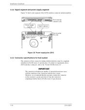
SATA interface and power connectors PCA Figure 3.7 Connector locations C141-E293 3-9 Figure 3.7 shows the locations of these connectors and terminals. 3.3 Connections with Host System 3.3 Connections with Host System 3.3.1 Device connector The disk drive has the SATA interface connectors listed below for connecting external devices.
SATA interface and power connectors PCA Figure 3.7 Connector locations C141-E293 3-9 Figure 3.7 shows the locations of these connectors and terminals. 3.3 Connections with Host System 3.3 Connections with Host System 3.3.1 Device connector The disk drive has the SATA interface connectors listed below for connecting external devices.
Maintenance Manual
Page 54
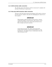
...specification. 3-10 C141-E293 Installation Conditions 3.3.2 Signal segment and power supply segment Figure 3.8 shows each segment of requirements about SATA interface connector, refer to the "Serial-ATA Revision 2.6." For detail of the SATA interface connector and pin numbers. Therefore, we recommend that the customer evaluate the connector on the customer's system and...Serial-ATA Revision 2.6 specification. The connection reliability per number of insertion/extractions varies with the condition of host system for mating with the disk drive must be compliant with the host system.
...specification. 3-10 C141-E293 Installation Conditions 3.3.2 Signal segment and power supply segment Figure 3.8 shows each segment of requirements about SATA interface connector, refer to the "Serial-ATA Revision 2.6." For detail of the SATA interface connector and pin numbers. Therefore, we recommend that the customer evaluate the connector on the customer's system and...Serial-ATA Revision 2.6 specification. The connection reliability per number of insertion/extractions varies with the condition of host system for mating with the disk drive must be compliant with the host system.
Maintenance Manual
Page 55
...compliant with the Serial ATA Revision 2.6 specification. 3.3.5 Note about SATA interface cable connection Take note of the following precaution about plugging a SATA interface cable into the SATA interface connector of the disk drive and plugging the connector into a host receptacle: When plugging together... the disk drive SATA interface connector and the host receptacle or SATA interface cable connector, do not...
...compliant with the Serial ATA Revision 2.6 specification. 3.3.5 Note about SATA interface cable connection Take note of the following precaution about plugging a SATA interface cable into the SATA interface connector of the disk drive and plugging the connector into a host receptacle: When plugging together... the disk drive SATA interface connector and the host receptacle or SATA interface cable connector, do not...

Maintenance Manual
Page 62
... heads onto the SA area and reads out the system information. When the self-diagnosis terminates successfully, the disk drive starts the spindle motor. f) The drive becomes ready. This collects data for VCM torque and mechanical external forces applied to the actuator, and updates the .... 4-6 C141-E293 Theory of Device Operation 4.4 Power-on Sequence Figure 4.3 describes the operation sequence of the disk drive at power-on , the disk drive initializes its SATA interface block. The outline is loaded on the disk. d) After confirming that the spindle motor has reached rated speed...
... heads onto the SA area and reads out the system information. When the self-diagnosis terminates successfully, the disk drive starts the spindle motor. f) The drive becomes ready. This collects data for VCM torque and mechanical external forces applied to the actuator, and updates the .... 4-6 C141-E293 Theory of Device Operation 4.4 Power-on Sequence Figure 4.3 describes the operation sequence of the disk drive at power-on , the disk drive initializes its SATA interface block. The outline is loaded on the disk. d) After confirming that the spindle motor has reached rated speed...

Maintenance Manual
Page 63
c) Self-diagnosis 2 - Internal register write/read test The spindle motor starts. Data buffer write/read test d) Confirming spindle motor speed Load the head assembly e) Initial on-track and read out of system information f) Drive ready state (command waiting state) g) Execute self-calibration End Figure 4.3 Power-on Start a) SATA I/F Initialization b) Self-diagnosis 1 - Work RAM write/read test - MPU bus test - 4.4 Power-on Sequence Power-on operation sequence C141-E293 4-7
c) Self-diagnosis 2 - Internal register write/read test The spindle motor starts. Data buffer write/read test d) Confirming spindle motor speed Load the head assembly e) Initial on-track and read out of system information f) Drive ready state (command waiting state) g) Execute self-calibration End Figure 4.3 Power-on Start a) SATA I/F Initialization b) Self-diagnosis 1 - Work RAM write/read test - MPU bus test - 4.4 Power-on Sequence Power-on operation sequence C141-E293 4-7

Maintenance Manual
Page 92
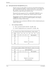
... OFF) 1 80h ALIGN Transmit_only Mode (Scramble ON) (*1) 1 - 1 - - - - Bidirectional FIS has the following combinations of pattern definitions are supported: Table 5.4 BIST combinations T A S L F P V SC Reg Contents - - - 1 - - 1 09h SATA Phy Analog Loopback Mode - - - 1 - - - 10h Far End Retimed Loopback Mode 1 1 - - - - - E4h No ALIGN Transmit_only with primitive Mode (Scramble ON) (*1) 1 1 1 - - 1 - Interface 5.2.3.6 BIST Active - This FIS can...
... OFF) 1 80h ALIGN Transmit_only Mode (Scramble ON) (*1) 1 - 1 - - - - Bidirectional FIS has the following combinations of pattern definitions are supported: Table 5.4 BIST combinations T A S L F P V SC Reg Contents - - - 1 - - 1 09h SATA Phy Analog Loopback Mode - - - 1 - - - 10h Far End Retimed Loopback Mode 1 1 - - - - - E4h No ALIGN Transmit_only with primitive Mode (Scramble ON) (*1) 1 1 1 - - 1 - Interface 5.2.3.6 BIST Active - This FIS can...

Maintenance Manual
Page 96
... - Bit 2: - This bit indicates an error except for bad sector, uncorrectable error and SB not found during RECALIBRATE command execution. This bit indicates that a SATA communication error has been encountered during the read process. Track 0 Not Found (TK0NF). X '04': - Bit 1: - Unused ID Not Found (IDNF). Aborted...error occurred. [Diagnostic code] - In this case, bit3 and bit2 are valid when the ERR bit of the Status field is abnormal. SATA Frame Error Read (SF RR). In this case, bit4 and bit2 are set both . This bit indicates that track 0 was not found...
... - Bit 2: - This bit indicates an error except for bad sector, uncorrectable error and SB not found during RECALIBRATE command execution. This bit indicates that a SATA communication error has been encountered during the read process. Track 0 Not Found (TK0NF). X '04': - Bit 1: - Unused ID Not Found (IDNF). Aborted...error occurred. [Diagnostic code] - In this case, bit3 and bit2 are valid when the ERR bit of the Status field is abnormal. SATA Frame Error Read (SF RR). In this case, bit4 and bit2 are set both . This bit indicates that track 0 was not found...

Maintenance Manual
Page 105
... ER Error information Note: Also executable in the LBA mode. • Error reporting conditions (1) An error was detected during head positioning (ST = 51h, ER = 02h). (2) A SATA communication error occurred (ST = 51h, ER = 14h).
... ER Error information Note: Also executable in the LBA mode. • Error reporting conditions (1) An error was detected during head positioning (ST = 51h, ER = 02h). (2) A SATA communication error occurred (ST = 51h, ER = 14h).

Maintenance Manual
Page 108
... will be exceeded by the host, the device performs an implied seek. A sector count of the last sector written. If the head is not on . (5) A SATA communication error occurred (ST = 51h, ER = 14h). (6) An error other than the above errors occurred (ST = 51h, ER = 04h). 5-34 C141-E293 This state is...
... will be exceeded by the host, the device performs an implied seek. A sector count of the last sector written. If the head is not on . (5) A SATA communication error occurred (ST = 51h, ER = 14h). (6) An error other than the above errors occurred (ST = 51h, ER = 04h). 5-34 C141-E293 This state is...

Maintenance Manual
Page 110
... write cache is enabled, if the status indicating a completed transfer (STS = 50h) is posted. This state is a read error occurred disk (ST = 51h, ER = 40h). (6) A SATA communication error occurred (ST = 51h, ER = 14h). (7) An error other than the above errors occurred (ST = 51h, ER = 04h). The verify operation is cleared the...
... write cache is enabled, if the status indicating a completed transfer (STS = 50h) is posted. This state is a read error occurred disk (ST = 51h, ER = 40h). (6) A SATA communication error occurred (ST = 51h, ER = 14h). (7) An error other than the above errors occurred (ST = 51h, ER = 04h). The verify operation is cleared the...

Maintenance Manual
Page 112
The Sector Count field indicates the number of a sector was not found (ST = 51h, ER = 01h). (5) A SATA communication error occurred (ST = 51h, ER = 14h). (6) An error other than the above errors occurred (ST = 51h, ER = 04h). Interface (5) READ VERIFY SECTOR(S) (X '40' or X '...
The Sector Count field indicates the number of a sector was not found (ST = 51h, ER = 01h). (5) A SATA communication error occurred (ST = 51h, ER = 14h). (6) An error other than the above errors occurred (ST = 51h, ER = 04h). Interface (5) READ VERIFY SECTOR(S) (X '40' or X '...

Maintenance Manual
Page 114
... the status to the track and selects the head specified in which the sector is not possible because an error occurred (ST = 51h, ER = 10h). (3) A SATA communication error occurred (ST = 51h, ER = 14h). Interface (6) SEEK (X '70' to X '7F') This command performs a seek operation to the host system...
... the status to the track and selects the head specified in which the sector is not possible because an error occurred (ST = 51h, ER = 10h). (3) A SATA communication error occurred (ST = 51h, ER = 14h). Interface (6) SEEK (X '70' to X '7F') This command performs a seek operation to the host system...

Maintenance Manual
Page 115
... 5-41 5.3 Host Commands (7) EXECUTE DEVICE DIAGNOSTIC (X '90') This command performs an internal diagnostic test (self-diagnosis) of power-on diagnostic test. • Error reporting conditions (1) A SATA communication error occurred (ST = 51h, ER = 14h). Table 5.6 Diagnostic code Code Result of diagnostic X '00' X '01' X '02' X '03' X '04' X '05' X '06' Format Unit is not...
... 5-41 5.3 Host Commands (7) EXECUTE DEVICE DIAGNOSTIC (X '90') This command performs an internal diagnostic test (self-diagnosis) of power-on diagnostic test. • Error reporting conditions (1) A SATA communication error occurred (ST = 51h, ER = 14h). Table 5.6 Diagnostic code Code Result of diagnostic X '00' X '01' X '02' X '03' X '04' X '05' X '06' Format Unit is not...
Maintenance Manual
Page 116
... with the command ignoring any setting of LBA mode. • Error reporting conditions (1) "00h" is always performed in the SC field (ST = 51h, ER = 04h). (2) A SATA communication error occurred (ST = 51h, ER = 14h).
... with the command ignoring any setting of LBA mode. • Error reporting conditions (1) "00h" is always performed in the SC field (ST = 51h, ER = 04h). (2) A SATA communication error occurred (ST = 51h, ER = 14h).


