
Maintenance Manual
Page 5
..., troubleshooting, and removal/replacement of the disk drive. Preface This manual describes MJA2500BH, MJA2400BH, MJA2320BH, MJA2250BH, MJA2160BH, MJA2120BH, MJA2080BH model of the disk drive. This manual describes the specifications and functions of the drives and explains in detail how to read this ... Series, 2.5-inch hard disk drives. Glossary The glossary describes the technical terms that is compatible with the Serial-ATA interface. CHAPTER 4 Theory of Device Operation This chapter describes the operation theory of the disk drive and describes their implementations...
..., troubleshooting, and removal/replacement of the disk drive. Preface This manual describes MJA2500BH, MJA2400BH, MJA2320BH, MJA2250BH, MJA2160BH, MJA2120BH, MJA2080BH model of the disk drive. This manual describes the specifications and functions of the drives and explains in detail how to read this ... Series, 2.5-inch hard disk drives. Glossary The glossary describes the technical terms that is compatible with the Serial-ATA interface. CHAPTER 4 Theory of Device Operation This chapter describes the operation theory of the disk drive and describes their implementations...

Maintenance Manual
Page 6
... the alert messages. Ensure that could result in this manual. This indicates information that the disk drive is an example: (Example) Data corruption: Avoid mounting the disk drive near strong magnetic sources such as notebook PCs, and to be used in the "Important Alert Items...Abbreviations This section gives the meanings of the definitions used within environmental specification. (please refer to the product or other property may occur if the user does not perform the procedure correctly. Conventions for mobile system as loud speakers. An alert message consists of an alert ...
... the alert messages. Ensure that could result in this manual. This indicates information that the disk drive is an example: (Example) Data corruption: Avoid mounting the disk drive near strong magnetic sources such as notebook PCs, and to be used in the "Important Alert Items...Abbreviations This section gives the meanings of the definitions used within environmental specification. (please refer to the product or other property may occur if the user does not perform the procedure correctly. Conventions for mobile system as loud speakers. An alert message consists of an alert ...

Maintenance Manual
Page 8
... shipped as a component to Section 5.1.6. Compliance with regard to hot-plugging vary depending on Serial ATA Revision 2.6 Specification. Preface Hot Plug These drives support Hot Plug which is based on the specific requirements and environment-related conditions of China This product is connected by Electronic Information Products of the People's Republic of the...
... shipped as a component to Section 5.1.6. Compliance with regard to hot-plugging vary depending on Serial ATA Revision 2.6 Specification. Preface Hot Plug These drives support Hot Plug which is based on the specific requirements and environment-related conditions of China This product is connected by Electronic Information Products of the People's Republic of the...

Maintenance Manual
Page 14
Contents 2.2 System Configuration 2-3 2.2.1 SATA interface 2-3 2.2.2 Drive connection 2-3 CHAPTER 3 Installation Conditions 3-1 3.1 Dimensions ...3-2 3.2 Mounting...3-3 3.3 Connections with Host System 3-9 3.3.1 Device connector 3-9 3.3.2 Signal segment and power supply segment 3-10 3.3.3 Connector specifications for host system 3-10 3.3.4 SATA interface cable connection 3-11 3.3.5 Note about SATA interface cable connection 3-11 CHAPTER 4 Theory of Device Operation 4-1 4.1 Outline...4-2 4.2 Subassemblies 4-2 4.2.1 Disk ...4-2 4.2.2 Spindle 4-2 4.2.3 ...
Contents 2.2 System Configuration 2-3 2.2.1 SATA interface 2-3 2.2.2 Drive connection 2-3 CHAPTER 3 Installation Conditions 3-1 3.1 Dimensions ...3-2 3.2 Mounting...3-3 3.3 Connections with Host System 3-9 3.3.1 Device connector 3-9 3.3.2 Signal segment and power supply segment 3-10 3.3.3 Connector specifications for host system 3-10 3.3.4 SATA interface cable connection 3-11 3.3.5 Note about SATA interface cable connection 3-11 CHAPTER 4 Theory of Device Operation 4-1 4.1 Outline...4-2 4.2 Subassemblies 4-2 4.2.1 Disk ...4-2 4.2.2 Spindle 4-2 4.2.3 ...

Maintenance Manual
Page 15
... servo format 4-14 4.7.3 Servo frame format 4-16 4.7.4 Actuator motor control 4-17 4.7.5 Spindle motor control 4-18 CHAPTER 5 Interface 5-1 5.1 Physical Interface 5-2 5.1.1 Interface signals 5-2 5.1.2 Signal interface regulation 5-4 5.1.3 Electrical specifications 5-6 5.1.4 Connector pinouts 5-7 5.1.5 P11 function 5-8 5.1.6 Hot Plug 5-10 5.2 Logical Interface 5-11 5.2.1 Communication layers 5-12 5.2.2 Outline of the Shadow Block Register 5-13 5.2.3 Outline of the frame information...
... servo format 4-14 4.7.3 Servo frame format 4-16 4.7.4 Actuator motor control 4-17 4.7.5 Spindle motor control 4-18 CHAPTER 5 Interface 5-1 5.1 Physical Interface 5-2 5.1.1 Interface signals 5-2 5.1.2 Signal interface regulation 5-4 5.1.3 Electrical specifications 5-6 5.1.4 Connector pinouts 5-7 5.1.5 P11 function 5-8 5.1.6 Hot Plug 5-10 5.2 Logical Interface 5-11 5.2.1 Communication layers 5-12 5.2.2 Outline of the Shadow Block Register 5-13 5.2.3 Outline of the frame information...

Maintenance Manual
Page 21
...Table 1.2 Table 1.3 Table 1.4 Table 1.5 Table 1.6 Table 1.7 Table 1.8 Specifications 1-5 Examples of model names and product numbers 1-6 Current and power dissipation 1-9 Environmental specifications 1-10 Acoustic noise specification 1-11 Shock and vibration specification 1-11 Advanced Power Management 1-15 Interface power management 1-17 Table 3.1 Surface ...Self-test execution status 5-62 Off-line data collection capability 5-63 Failure prediction capability flag 5-63 Drive error logging capability 5-64 Log Directory Data Format 5-64 Data format of SMART Summary Error Log 5-...
...Table 1.2 Table 1.3 Table 1.4 Table 1.5 Table 1.6 Table 1.7 Table 1.8 Specifications 1-5 Examples of model names and product numbers 1-6 Current and power dissipation 1-9 Environmental specifications 1-10 Acoustic noise specification 1-11 Shock and vibration specification 1-11 Advanced Power Management 1-15 Interface power management 1-17 Table 3.1 Surface ...Self-test execution status 5-62 Off-line data collection capability 5-63 Failure prediction capability flag 5-63 Drive error logging capability 5-64 Log Directory Data Format 5-64 Data format of SMART Summary Error Log 5-...
Maintenance Manual
Page 23
... Advanced Power Management (APM) 1.12 Interface Power Management (IPM) Overview and features are described in disk controllers. C141-E293 1-1 These disk drives use the SATA interface protocol which has a high-speed interface data transfer rate. The disk drive is 2.5-inch hard disk drives with built-in this chapter, and specifications and power requirement are described.
... Advanced Power Management (APM) 1.12 Interface Power Management (IPM) Overview and features are described in disk controllers. C141-E293 1-1 These disk drives use the SATA interface protocol which has a high-speed interface data transfer rate. The disk drive is 2.5-inch hard disk drives with built-in this chapter, and specifications and power requirement are described.
Maintenance Manual
Page 27
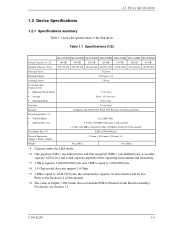
...048,576 bytes; Table 1.1 Specifications (1/2) MJA2500BH MJA2400BH MJA2320BH MJA2250BH MJA2160BH MJA2120BH MJA2080BH Format Capacity (*1, *2) 500 GB 400 GB 320 GB 250 GB 160 GB 120 GB 80 GB Number of Sectors (User) 976... (*6) Weight 101 g (Max.) 96 g (Max.) *1: Capacity under the LBA mode. *2: One gigabyte (GB) = one billion bytes and One megabyte (MB) = one million bytes; C141-E293 1-5 the actual buffer ... will be less and actual capacity depends on the operating environment and formatting. *3: 1 GB is equal to 1,000,000,000 bytes and 1 MB is equal to 1,000,000...
...048,576 bytes; Table 1.1 Specifications (1/2) MJA2500BH MJA2400BH MJA2320BH MJA2250BH MJA2160BH MJA2120BH MJA2080BH Format Capacity (*1, *2) 500 GB 400 GB 320 GB 250 GB 160 GB 120 GB 80 GB Number of Sectors (User) 976... (*6) Weight 101 g (Max.) 96 g (Max.) *1: Capacity under the LBA mode. *2: One gigabyte (GB) = one billion bytes and One megabyte (MB) = one million bytes; C141-E293 1-5 the actual buffer ... will be less and actual capacity depends on the operating environment and formatting. *3: 1 GB is equal to 1,000,000,000 bytes and 1 MB is equal to 1,000,000...

Maintenance Manual
Page 28
... listed in Table 1.2 since some models have been customized and have specifications that of the drive being replaced. MJA2500BH 500 GB M3 Depth 3 CA07083-B391 (1.5 Gbps model) CA07083-B341 (3.0 Gbps model) (*2) MJA2400BH 400 GB M3 Depth 3 CA07083-B390 (1.5 Gbps model) CA07083-B340 (3.0 Gbps model) (*2) MJA2320BH 320 GB M3 Depth 3 CA07083-B092/B382 (1.5 Gbps model) CA07083-B042/B332...
... listed in Table 1.2 since some models have been customized and have specifications that of the drive being replaced. MJA2500BH 500 GB M3 Depth 3 CA07083-B391 (1.5 Gbps model) CA07083-B341 (3.0 Gbps model) (*2) MJA2400BH 400 GB M3 Depth 3 CA07083-B390 (1.5 Gbps model) CA07083-B340 (3.0 Gbps model) (*2) MJA2320BH 320 GB M3 Depth 3 CA07083-B092/B382 (1.5 Gbps model) CA07083-B042/B332...
Maintenance Manual
Page 32
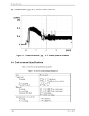
... 0 1 2 3 [sec] Figure 1.3 Current fluctuation (Typ.) at +5 V when power is turned on 1.4 Environmental Specifications Table 1.4 lists the environmental specifications. Table 1.4 Environmental specifications Item Temperature • Operating • Non-operating • Thermal Gradient Humidity • Operating • Non-operating •...; Maximum Wet Bulb Altitude (relative to sea level) • Operating • Non-operating Specification 5 °C to 55 °C (ambient) 5 °C to 60 °C (disk enclosure surface) -40 °C to...
... 0 1 2 3 [sec] Figure 1.3 Current fluctuation (Typ.) at +5 V when power is turned on 1.4 Environmental Specifications Table 1.4 lists the environmental specifications. Table 1.4 Environmental specifications Item Temperature • Operating • Non-operating • Thermal Gradient Humidity • Operating • Non-operating •...; Maximum Wet Bulb Altitude (relative to sea level) • Operating • Non-operating Specification 5 °C to 55 °C (ambient) 5 °C to 60 °C (disk enclosure surface) -40 °C to...

Maintenance Manual
Page 33
...specification. Table 1.6 Shock and vibration specification Item Vibration (Swept sine, 1/4 octave per minute) • Operating Specification 5 to 500 Hz, 9.8m/s2 0-peak (1G 0-peak) (without non-recovered errors) Non-operating Shock (half-sine pulse) • Operating • Non-operating 5 to 500... Acoustic noise specification Item Specification • Idle mode (DRIVE READY) Sound Power 2.0B [MJA2250BH/MJA2160BH/MJA2120BH/MJA2080BH] 2.4B [MJA2500BH/MJA2400BH/MJA2320BH] Sound Pressure (at 0.3m) 22dB [MJA2250BH/MJA2160BH/MJA2120BH/MJA2080BH] 28dB [MJA2500BH/MJA2400BH/MJA2320BH] ...
...specification. Table 1.6 Shock and vibration specification Item Vibration (Swept sine, 1/4 octave per minute) • Operating Specification 5 to 500 Hz, 9.8m/s2 0-peak (1G 0-peak) (without non-recovered errors) Non-operating Shock (half-sine pulse) • Operating • Non-operating 5 to 500... Acoustic noise specification Item Specification • Idle mode (DRIVE READY) Sound Power 2.0B [MJA2250BH/MJA2160BH/MJA2120BH/MJA2080BH] 2.4B [MJA2500BH/MJA2400BH/MJA2320BH] Sound Pressure (at 0.3m) 22dB [MJA2250BH/MJA2160BH/MJA2120BH/MJA2080BH] 28dB [MJA2500BH/MJA2400BH/MJA2320BH] ...

Maintenance Manual
Page 47
..., see the "FUJITSU 2.5-INCH HDD INTEGRATION GUIDANCE (C141-E144)." (1) Orientation The disk drives can be 0.49N•m (5kgf•cm). The tightening torque must be mounted in Figure 3.2. C141-E293 3-3 The mounting frame is attached. Use M3 screw for the mounting screw and the screw length should satisfy the specification in any direction...
..., see the "FUJITSU 2.5-INCH HDD INTEGRATION GUIDANCE (C141-E144)." (1) Orientation The disk drives can be 0.49N•m (5kgf•cm). The tightening torque must be mounted in Figure 3.2. C141-E293 3-3 The mounting frame is attached. Use M3 screw for the mounting screw and the screw length should satisfy the specification in any direction...
Maintenance Manual
Page 54
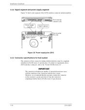
... connector on the customer's system and select it from the PCA side Figure 3.8 Power supply pins (CN1) 3.3.3 Connector specifications for mating with the disk drive must be compliant with the Serial ATA Revision 2.6 specification. 3-10 C141-E293 For detail of host system for host system The connector of requirements about SATA interface connector... the connector side P1 pins in the power S1 pins in the signal supply segment segment View from the connectors complying with Serial-ATA Revision 2.6 specification.
... connector on the customer's system and select it from the PCA side Figure 3.8 Power supply pins (CN1) 3.3.3 Connector specifications for mating with the disk drive must be compliant with the Serial ATA Revision 2.6 specification. 3-10 C141-E293 For detail of host system for host system The connector of requirements about SATA interface connector... the connector side P1 pins in the power S1 pins in the signal supply segment segment View from the connectors complying with Serial-ATA Revision 2.6 specification.
Maintenance Manual
Page 55
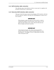
...interface Latch may lead to connect/remove the cable while releasing the Latch. Accordingly, be compliant with the Serial ATA Revision 2.6 specification. 3.3.5 Note about SATA interface cable connection Take note of the following precaution about plugging a SATA interface cable into the SATA interface... connector of the disk drive and plugging the connector into a host receptacle: When plugging together the disk drive SATA interface connector and the host receptacle or SATA interface cable connector, do not apply...
...interface Latch may lead to connect/remove the cable while releasing the Latch. Accordingly, be compliant with the Serial ATA Revision 2.6 specification. 3.3.5 Note about SATA interface cable connection Take note of the following precaution about plugging a SATA interface cable into the SATA interface... connector of the disk drive and plugging the connector into a host receptacle: When plugging together the disk drive SATA interface connector and the host receptacle or SATA interface cable connector, do not apply...
Maintenance Manual
Page 74
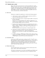
...on the MPU manufactured by itself based on the condition of the target, controls a stable rotation with hardware. The SVC starts a phase switching by Fujitsu. The firmware calculates time of one rotation from the SVC, and waits till the rotational speed reaches 5,400 rpm. d) During phase switching, the ...control Hall-less three-phase twelve-pole motor is used for the spindle motor, and the PWM type current control circuit is sent for a specific period, the MPU resets the SVC and starts from the beginning. The spindle motor is changed in the motor is controlled by sending several...
...on the MPU manufactured by itself based on the condition of the target, controls a stable rotation with hardware. The SVC starts a phase switching by Fujitsu. The firmware calculates time of one rotation from the SVC, and waits till the rotational speed reaches 5,400 rpm. d) During phase switching, the ...control Hall-less three-phase twelve-pole motor is used for the spindle motor, and the PWM type current control circuit is sent for a specific period, the MPU resets the SVC and starts from the beginning. The spindle motor is changed in the motor is controlled by sending several...

Maintenance Manual
Page 78
COMRESET/COMINIT 106.7 ns 320 ns COMWAKE 106.7 ns 106.7 ns 5-4 C141-E293 Interface 5.1.2 Signal interface regulation 5.1.2.1 Out of band signaling During OOB signaling transmissions, the differential and common mode levels of the signal lines shall comply with the same electrical specifications as for in-band data transmission, specified as follows.
COMRESET/COMINIT 106.7 ns 320 ns COMWAKE 106.7 ns 106.7 ns 5-4 C141-E293 Interface 5.1.2 Signal interface regulation 5.1.2.1 Out of band signaling During OOB signaling transmissions, the differential and common mode levels of the signal lines shall comply with the same electrical specifications as for in-band data transmission, specified as follows.
Maintenance Manual
Page 80
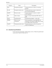
... error in the "Serial-ATA Revision 2.6." 5-6 C141-E293 After transmission of any of frame Synchronization Wait for transmission. 5.1.3 Electrical specifications For the electrical requirements of a frame. Current node (host or device) is receiving payload. always idle. Current node (host ...the EOF, the transmitter will transmit WTRM while waiting for reception status from receiver. Payload and CRC follow to "Electrical specifications" section in received payload. Current node (host or device) has payload ready for frame termination Transmission data ready Description...
... error in the "Serial-ATA Revision 2.6." 5-6 C141-E293 After transmission of any of frame Synchronization Wait for transmission. 5.1.3 Electrical specifications For the electrical requirements of a frame. Current node (host or device) is receiving payload. always idle. Current node (host ...the EOF, the transmitter will transmit WTRM while waiting for reception status from receiver. Payload and CRC follow to "Electrical specifications" section in received payload. Current node (host or device) has payload ready for frame termination Transmission data ready Description...
Maintenance Manual
Page 81
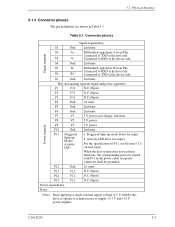
... P10 Gnd 2nd mate P11 Staggered Spin-up Mode/ Activity LED • Staggered Spin-up mode detect for input • Activity LED drive for output For the specification of 5 V enables this drive to operate it is unnecessary to be grounded. C141-E293 5-7 5.1 Physical Interface 5.1.4 Connector pinouts The pin definitions are shown in the...
... P10 Gnd 2nd mate P11 Staggered Spin-up Mode/ Activity LED • Staggered Spin-up mode detect for input • Activity LED drive for output For the specification of 5 V enables this drive to operate it is unnecessary to be grounded. C141-E293 5-7 5.1 Physical Interface 5.1.4 Connector pinouts The pin definitions are shown in the...
Maintenance Manual
Page 84
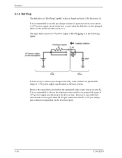
... is recommended to the Serial ATA Revision 2.6.) The equivalent circuit of +5V power supply at Hot Plugging is in permissible range of +5V power supply specification at the host system. It is necessary to the equivalent circuit when the optimized value of +5V power supply... specification at the host system. Refer to choose pre-charge resistor RL value, which is in permissible range of pre-charge resistor RL. Interface 5.1.6 Hot Plug The disk drive is "Hot Plug Capable" which is based on the insertion speed...
... is recommended to the Serial ATA Revision 2.6.) The equivalent circuit of +5V power supply at Hot Plugging is in permissible range of +5V power supply specification at the host system. It is necessary to the equivalent circuit when the optimized value of +5V power supply... specification at the host system. Refer to choose pre-charge resistor RL value, which is in permissible range of pre-charge resistor RL. Interface 5.1.6 Hot Plug The disk drive is "Hot Plug Capable" which is based on the insertion speed...

Maintenance Manual
Page 97
... between X '01' and [the number of PIO transfer, SC=1 indicates the normal completion. C141-E293 5-23 5.2 Logical Interface (2) Features Field (exp) The Features Field provides specific feature to the error. When this field indicates 0 at the completion of the command execution, this indicates that the command is not completed successfully, this...
... between X '01' and [the number of PIO transfer, SC=1 indicates the normal completion. C141-E293 5-23 5.2 Logical Interface (2) Features Field (exp) The Features Field provides specific feature to the error. When this field indicates 0 at the completion of the command execution, this indicates that the command is not completed successfully, this...
