
Maintenance Manual
Page 21
...1.6 Table 1.7 Table 1.8 Specifications 1-5 Examples of model names and product numbers 1-6 Current and power dissipation 1-9 Environmental specifications 1-10 Acoustic noise specification 1-11 Shock and vibration specification 1-11 Advanced Power Management 1-15 Interface power management 1-17 Table 3.1 Surface temperature measurement points and standard...62 Self-test execution status 5-62 Off-line data collection capability 5-63 Failure prediction capability flag 5-63 Drive error logging capability 5-64 Log Directory Data Format 5-64 Data format of SMART Summary Error Log 5-65 ...
...1.6 Table 1.7 Table 1.8 Specifications 1-5 Examples of model names and product numbers 1-6 Current and power dissipation 1-9 Environmental specifications 1-10 Acoustic noise specification 1-11 Shock and vibration specification 1-11 Advanced Power Management 1-15 Interface power management 1-17 Table 3.1 Surface temperature measurement points and standard...62 Self-test execution status 5-62 Off-line data collection capability 5-63 Failure prediction capability flag 5-63 Drive error logging capability 5-64 Log Directory Data Format 5-64 Data format of SMART Summary Error Log 5-65 ...
Maintenance Manual
Page 23
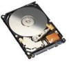
The disk drive is 2.5-inch hard disk drives with built-in this chapter, and specifications and power requirement are described. These disk drives use the SATA interface protocol which has a high-speed interface data transfer rate. C141-E293 1-1 CHAPTER 1 Device Overview 1.1 Features 1.2 Device Specifications 1.3 Power Requirements 1.4 Environmental Specifications 1.5 Acoustic Noise 1.6 Shock and Vibration 1.7 Reliability 1.8 Error Rate...
The disk drive is 2.5-inch hard disk drives with built-in this chapter, and specifications and power requirement are described. These disk drives use the SATA interface protocol which has a high-speed interface data transfer rate. C141-E293 1-1 CHAPTER 1 Device Overview 1.1 Features 1.2 Device Specifications 1.3 Power Requirements 1.4 Environmental Specifications 1.5 Acoustic Noise 1.6 Shock and Vibration 1.7 Reliability 1.8 Error Rate...

Maintenance Manual
Page 25
... range (5 °C to 60 °C at DE surface). (3) Low noise and vibration In Ready status (while the device is 2.0B [MJA2250BH/MJA2160BH/ MJA2120BH/MJA2080BH] / 2.4B [MJA2500BH/MJA2400BH/MJA2320BH]. Executing a diagnostic function of the controller and disk drive. 1.1 Features (2) Wide temperature range The disk drive can be transferred instead. (4) Error correction and retry by the...
... range (5 °C to 60 °C at DE surface). (3) Low noise and vibration In Ready status (while the device is 2.0B [MJA2250BH/MJA2160BH/ MJA2120BH/MJA2080BH] / 2.4B [MJA2500BH/MJA2400BH/MJA2320BH]. Executing a diagnostic function of the controller and disk drive. 1.1 Features (2) Wide temperature range The disk drive can be transferred instead. (4) Error correction and retry by the...

Maintenance Manual
Page 33
...) 11ms duration (no damage) C141-E293 1-11 Table 1.5 Acoustic noise specification Item Specification • Idle mode (DRIVE READY) Sound Power 2.0B [MJA2250BH/MJA2160BH/MJA2120BH/MJA2080BH] 2.4B [MJA2500BH/MJA2400BH/MJA2320BH] Sound Pressure (at 0.3m) 22dB [MJA2250BH/MJA2160BH/MJA2120BH/MJA2080BH] 28dB [MJA2500BH/MJA2400BH/MJA2320BH] Note: Measure the noise from the cover top surface. 1.6 Shock and Vibration Table...
...) 11ms duration (no damage) C141-E293 1-11 Table 1.5 Acoustic noise specification Item Specification • Idle mode (DRIVE READY) Sound Power 2.0B [MJA2250BH/MJA2160BH/MJA2120BH/MJA2080BH] 2.4B [MJA2500BH/MJA2400BH/MJA2320BH] Sound Pressure (at 0.3m) 22dB [MJA2250BH/MJA2160BH/MJA2120BH/MJA2080BH] 28dB [MJA2500BH/MJA2400BH/MJA2320BH] Note: Measure the noise from the cover top surface. 1.6 Shock and Vibration Table...

Maintenance Manual
Page 43
... caused by external noise. (7) Controller circuit The controller circuit supports Serial-ATA interface, and it realized a high performance by each model). 2.2.2 Drive connection Operating System Application 1 Application 2 Driver Application 3 Serial ATA Adapter Disk Drive Disk Drive Figure 2.2 Drive system configuration C141-E293... (5) Air circulation system The disk enclosure (DE) is sealed to maintain the cleanliness of the rotating disk. The disk drive complies with ATA8-ACS, Serial ATA Revision 2.6 (Gen1i or Gen2i by integration into LSI. 2.2 System Configuration 2.2.1 SATA ...
... caused by external noise. (7) Controller circuit The controller circuit supports Serial-ATA interface, and it realized a high performance by each model). 2.2.2 Drive connection Operating System Application 1 Application 2 Driver Application 3 Serial ATA Adapter Disk Drive Disk Drive Figure 2.2 Drive system configuration C141-E293... (5) Air circulation system The disk enclosure (DE) is sealed to maintain the cleanliness of the rotating disk. The disk drive complies with ATA8-ACS, Serial ATA Revision 2.6 (Gen1i or Gen2i by integration into LSI. 2.2 System Configuration 2.2.1 SATA ...

Maintenance Manual
Page 67
... head positions. (2) Programmable filter circuit The programmable filter circuit has a low-pass filter function that eliminates unnecessary high frequency noise component and a high frequency boost-up function that equalizes the waveform of each zone is converted into 30 zones to increase... the input amplitude level fluctuates. The Viterbi detection circuit demodulates data according to the survivor path sequence. 4.6.4 Digital PLL circuit The drive uses constant density recording to set so that equalizes the head read signal to the Modified Extended Partial Response (MEEPR) waveform. (4)...
... head positions. (2) Programmable filter circuit The programmable filter circuit has a low-pass filter function that eliminates unnecessary high frequency noise component and a high frequency boost-up function that equalizes the waveform of each zone is converted into 30 zones to increase... the input amplitude level fluctuates. The Viterbi detection circuit demodulates data according to the survivor path sequence. 4.6.4 Digital PLL circuit The drive uses constant density recording to set so that equalizes the head read signal to the Modified Extended Partial Response (MEEPR) waveform. (4)...

Maintenance Manual
Page 295
...engineer and not where the failure was reported. The user may notice intermittent and indefinite failures such as overlong execution time, abnormal noise, abnormal odor, or failures in a test of functions. Then, by the host system. It is beyond the range of the disk... will reproduce the failure condition. The engineer then isolates the failure to separate the fault from the other systems. In normal operation, the disk drive itself or the host determines the processing (return or halt) following the detected failure state. For example, not having enough power supply reserve,...
...engineer and not where the failure was reported. The user may notice intermittent and indefinite failures such as overlong execution time, abnormal noise, abnormal odor, or failures in a test of functions. Then, by the host system. It is beyond the range of the disk... will reproduce the failure condition. The engineer then isolates the failure to separate the fault from the other systems. In normal operation, the disk drive itself or the host determines the processing (return or halt) following the detected failure state. For example, not having enough power supply reserve,...

Maintenance Manual
Page 297
... is less than 100 mV. If possible, replace the disk drive. 7.3 Troubleshooting Procedure Table 7.3 System level and field troubleshooting Check to be made Recommended work DC power voltage level DC power ripple noise SATA Interface Connection (Including a Connection of Power Segment) System ...cable System diagnostic test Intermittent or indefinite error Confirm that the SATA interface at the drive is properly connected with the system. Refer to ...
... is less than 100 mV. If possible, replace the disk drive. 7.3 Troubleshooting Procedure Table 7.3 System level and field troubleshooting Check to be made Recommended work DC power voltage level DC power ripple noise SATA Interface Connection (Including a Connection of Power Segment) System ...cable System diagnostic test Intermittent or indefinite error Confirm that the SATA interface at the drive is properly connected with the system. Refer to ...
Maintenance Manual
Page 307
... 6-5 COMRESET response 6-21 COMRESET sequence 5-188 COMRESET, response to 6-4 conceptual layer, conceptual diagram 5-11 condition, installation 3-1 configuration device 2-1, 2-2 drive system 2-3 C141-E293 IN-1 Index A A/D converter circuit 4-11 AAM 5-125 acceleration mode 4-18 acoustic noise 1-11 active field 5-26 active idle mode 6-8 active mode 6-8, 6-11 actuator 2-2, 4-2 actuator motor control 4-17 adaptability 1-2 advanced power...
... 6-5 COMRESET response 6-21 COMRESET sequence 5-188 COMRESET, response to 6-4 conceptual layer, conceptual diagram 5-11 condition, installation 3-1 configuration device 2-1, 2-2 drive system 2-3 C141-E293 IN-1 Index A A/D converter circuit 4-11 AAM 5-125 acceleration mode 4-18 acoustic noise 1-11 active field 5-26 active idle mode 6-8 active mode 6-8, 6-11 actuator 2-2, 4-2 actuator motor control 4-17 adaptability 1-2 advanced power...

Maintenance Manual
Page 310
...load/unload function 1-13 location of breather 3-5 location, connector 3-9 lock function, operation of 5-126 log directory data format 5-64 logical interface 5-11 low noise and vibration 1-3 low power idle mode 6-8 M maintenance 7-1, 7-2 maintenance level 7-5 maintenance requirement 7-3 master password 5-128 mean time between failure (MTBF)...mean time to reference cylinder 4-17 orientation 3-3 out of band signaling 5-4 outer guard band 4-14 outerview, disk drive 2-2 outline 4-2 outline of interface 6-11 power supply configuration 4-4 power supply pin 3-10 IN-4 C141-E293
...load/unload function 1-13 location of breather 3-5 location, connector 3-9 lock function, operation of 5-126 log directory data format 5-64 logical interface 5-11 low noise and vibration 1-3 low power idle mode 6-8 M maintenance 7-1, 7-2 maintenance level 7-5 maintenance requirement 7-3 master password 5-128 mean time between failure (MTBF)...mean time to reference cylinder 4-17 orientation 3-3 out of band signaling 5-4 outer guard band 4-14 outerview, disk drive 2-2 outline 4-2 outline of interface 6-11 power supply configuration 4-4 power supply pin 3-10 IN-4 C141-E293
