
Hardware Guide
Page 3
XG0224 Hardware Guide LICENSE AGREEMENT Product Name Total number of the following requirements ("Use Requirements"). Please note that Customer's use, installation or backup of the Product constitutes your acceptance of licenses XG Series Basic Software 1 Thank you for purchasing the XG Series switch product ("Hardware") and accompanying software ("Software," together with the Software is determined in subsection (1) above . The total number of Hardware that the Software infringes Intellectual Property Rights...
XG0224 Hardware Guide LICENSE AGREEMENT Product Name Total number of the following requirements ("Use Requirements"). Please note that Customer's use, installation or backup of the Product constitutes your acceptance of licenses XG Series Basic Software 1 Thank you for purchasing the XG Series switch product ("Hardware") and accompanying software ("Software," together with the Software is determined in subsection (1) above . The total number of Hardware that the Software infringes Intellectual Property Rights...
Hardware Guide
Page 5
... Safety ...15 Notes on Rack Mounting and Connecting a Powerstrip 15 About Fujitsu's Green Products ...15 Notes on Use ...16 Chapter 1 Getting Started 17 1.1 Items in the Package, Descriptions and Functions 18 1.1.1 Parts List ...18 1.1.2 Port Side ...19 1.1.3 Power Inlet Side ...22 1.1.4 Top Surface ...23 1.2 Options ...24 1.2.1 SFP Modules ...24 1.2.2 SFP+ Modules ...24 1.2.3 Compact Flash ...24 1.2.4 Expansion Card ...25 Chapter 2 Installation 27 2.1 Requirements for Installation Environment 28 2.1.1 Installation Requirements ...28 2.1.2 Space Requirements...
... Safety ...15 Notes on Rack Mounting and Connecting a Powerstrip 15 About Fujitsu's Green Products ...15 Notes on Use ...16 Chapter 1 Getting Started 17 1.1 Items in the Package, Descriptions and Functions 18 1.1.1 Parts List ...18 1.1.2 Port Side ...19 1.1.3 Power Inlet Side ...22 1.1.4 Top Surface ...23 1.2 Options ...24 1.2.1 SFP Modules ...24 1.2.2 SFP+ Modules ...24 1.2.3 Compact Flash ...24 1.2.4 Expansion Card ...25 Chapter 2 Installation 27 2.1 Requirements for Installation Environment 28 2.1.1 Installation Requirements ...28 2.1.2 Space Requirements...
Hardware Guide
Page 7
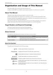
... operating instructions. Read this manual thoroughly before using this device. Note Indicates additional information to Console PC. Please follow them when using this device. Please follow them when using this device. Chapter Titles Chapter 1 Getting Started Chapter 2 Installation Contents This chapter lists the items that should be kept in an easy-toaccess location for persons who perform network management. Hint Indicates useful information for using this device set forth...
... operating instructions. Read this manual thoroughly before using this device. Note Indicates additional information to Console PC. Please follow them when using this device. Please follow them when using this device. Chapter Titles Chapter 1 Getting Started Chapter 2 Installation Contents This chapter lists the items that should be kept in an easy-toaccess location for persons who perform network management. Hint Indicates useful information for using this device set forth...
Hardware Guide
Page 12
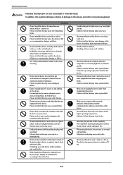
.... Failure to this device and other equipment that improper use this device near a radio or a TV set . 12 Do not insert or remove the extension card when the device is turned on the metal contacts of explosion if battery is extremely high/low or fluctuates greatly. Follow the operating temperature limit for access to, and cabling of damage to follow...
.... Failure to this device and other equipment that improper use this device near a radio or a TV set . 12 Do not insert or remove the extension card when the device is turned on the metal contacts of explosion if battery is extremely high/low or fluctuates greatly. Follow the operating temperature limit for access to, and cabling of damage to follow...
Hardware Guide
Page 13
... cleaning the device while in the chassis of the End User License Agreement stipulated within the User's Guide. In that the device is not guaranteed against unauthorized use at their own risk. • Fujitsu and its LAN port to operate falsely or to become statically charged again. Use of the device or upgrading the device firmware implies acceptance of the device. 13 XG0224 Hardware Guide Notes on the network can configure this device.
... cleaning the device while in the chassis of the End User License Agreement stipulated within the User's Guide. In that the device is not guaranteed against unauthorized use at their own risk. • Fujitsu and its LAN port to operate falsely or to become statically charged again. Use of the device or upgrading the device firmware implies acceptance of the device. 13 XG0224 Hardware Guide Notes on the network can configure this device.
Hardware Guide
Page 15
... Optical Transceiver Approved Vendor List (obtainable from the optical module's port openings. Assure a good ground connection exists before connecting power to the following Fujitsu Web site. In the USA, these SFP+ modules are not connected, invisible laser light may still be used for use in a rack by a label attached to a powerstrip within a rack, a large amount of current leakage may result in a rack, assure device operational temperature specification compliance, mechanical stability...
... Optical Transceiver Approved Vendor List (obtainable from the optical module's port openings. Assure a good ground connection exists before connecting power to the following Fujitsu Web site. In the USA, these SFP+ modules are not connected, invisible laser light may still be used for use in a rack by a label attached to a powerstrip within a rack, a large amount of current leakage may result in a rack, assure device operational temperature specification compliance, mechanical stability...
Hardware Guide
Page 16
... be enabled. • A User's Guide for the support engineer to restore the device, Please backup the configuration information on a timely manner and always maintain it may cause difficulties and delays for this case, contact Fujitsu or Fujitsu's certified support engineer for further instruction. • Do not turn the power off or reset the system during a firmware update, or the device cannot be restored to its normal condition by Fujitsu or Fujitsu's certified support...
... be enabled. • A User's Guide for the support engineer to restore the device, Please backup the configuration information on a timely manner and always maintain it may cause difficulties and delays for this case, contact Fujitsu or Fujitsu's certified support engineer for further instruction. • Do not turn the power off or reset the system during a firmware update, or the device cannot be restored to its normal condition by Fujitsu or Fujitsu's certified support...
Hardware Guide
Page 18
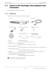
... the switch on to Serial Adapter) Straight cable with Licence Agreement) This manual describes the hardware of the following parts are included in the package. ‰ XG0224 ‰ Power Cable ‰ Console cable adapter ‰ Rack Mounting Brackets (Qty 2) ‰ M3 Countersunk Screws (Qty 8) ‰ CD-ROM ‰ Safety and Installation Guide ‰ XG0224 Hardware Guide (with Licence Agreement) • XG0224 The XG0224 Secure Switch. • Power Cable Cable to connect the XG0224 to an AC power source. • Console cable adapter (RJ45...
... the switch on to Serial Adapter) Straight cable with Licence Agreement) This manual describes the hardware of the following parts are included in the package. ‰ XG0224 ‰ Power Cable ‰ Console cable adapter ‰ Rack Mounting Brackets (Qty 2) ‰ M3 Countersunk Screws (Qty 8) ‰ CD-ROM ‰ Safety and Installation Guide ‰ XG0224 Hardware Guide (with Licence Agreement) • XG0224 The XG0224 Secure Switch. • Power Cable Cable to connect the XG0224 to an AC power source. • Console cable adapter (RJ45...
Hardware Guide
Page 19
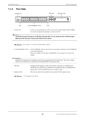
XG0224 Hardware Guide 1.1.2 Port Side Console Port Chapter 1 Getting Started SFP Slots Expansion Slot LED 10/100/1000BASE-T Ports LED • Console Port In order to set and operate the switch, use the console cable adapter and D-SUB9pin cross cable included in this jack. Reference User's Guide "1.1.5 Console Port Specifications" (pg.29) • 10/100/1000BASE-T Ports 10/100/1000BASE-T Ports. These ports for connecting to the PC. Reference "1.2.4 Expansion Card" (pg.25) 19 Items in a SFP slot will allow connection to a 100BASE-FX/ 1000BASE-SX...
XG0224 Hardware Guide 1.1.2 Port Side Console Port Chapter 1 Getting Started SFP Slots Expansion Slot LED 10/100/1000BASE-T Ports LED • Console Port In order to set and operate the switch, use the console cable adapter and D-SUB9pin cross cable included in this jack. Reference User's Guide "1.1.5 Console Port Specifications" (pg.29) • 10/100/1000BASE-T Ports 10/100/1000BASE-T Ports. These ports for connecting to the PC. Reference "1.2.4 Expansion Card" (pg.25) 19 Items in a SFP slot will allow connection to a 100BASE-FX/ 1000BASE-SX...
Hardware Guide
Page 20
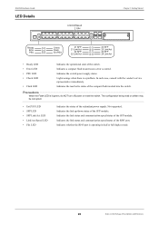
... there is operating in half or full duplex mode. 20 Items in the Package, Descriptions and Functions Indicates whether the RJ45 port is a problem. Not supported. Indicates a compact flash mount/access error occurred. The configuration being read /write status of the SFP module. Indicates the link status and communication speed/status of the redundant power supply. Precautions When the Flash LED is lit green, do NOT turn off power or reset the switch. Indicates the switch power supply status.
... there is operating in half or full duplex mode. 20 Items in the Package, Descriptions and Functions Indicates whether the RJ45 port is a problem. Not supported. Indicates a compact flash mount/access error occurred. The configuration being read /write status of the SFP module. Indicates the link status and communication speed/status of the redundant power supply. Precautions When the Flash LED is lit green, do NOT turn off power or reset the switch. Indicates the switch power supply status.
Hardware Guide
Page 21
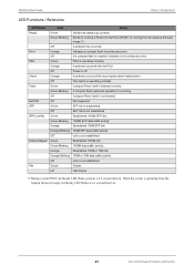
... Hardware Guide Chapter 1 Getting Started LED Functions / Behaviors LED Name Ready Error PSU Check Flash Ext.PSU SFP SFP Link/Act Link/Act/Speed Fdx State Green Green Blinking Off Orange Off Green Orange Off Orange Off Green Green Blinking Off Off Green Off Green Green Blinking Orange Orange Blinking Off Green Green Blinking Orange Orange Blinking Off Green Off Status Switch has started up correctly Switch is running a Power On Self Test (POST) or running from the backup firmware image (*) A problem has occurred Indicates a compact flash mount/access error If a compact flash is installed...
... Hardware Guide Chapter 1 Getting Started LED Functions / Behaviors LED Name Ready Error PSU Check Flash Ext.PSU SFP SFP Link/Act Link/Act/Speed Fdx State Green Green Blinking Off Orange Off Green Orange Off Orange Off Green Green Blinking Off Off Green Off Green Green Blinking Orange Orange Blinking Off Green Green Blinking Orange Orange Blinking Off Green Off Status Switch has started up correctly Switch is running a Power On Self Test (POST) or running from the backup firmware image (*) A problem has occurred Indicates a compact flash mount/access error If a compact flash is installed...
Hardware Guide
Page 22
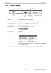
...command. Information Configuration Definition 1 Configuration Definition 2 Firmware Error Log File Name /cf0/config1 /cf0/config2 /cf0/firmware /cf0/elog • Compact Flash Card Slot The switch default configuration disables the dump switch. Insert a compact flash card to an installed compact flash card. XG0224 Hardware Guide 1.1.3 Power Inlet Side Product Manufacturing Label MAC Address Label Firmware Label Chapter 1 Getting Started Power Inlet Redundant PSU Connector Reset Switch Compact Flash Card Slot Dump Switch • Power Inlet AC power inlet for the power cable...
...command. Information Configuration Definition 1 Configuration Definition 2 Firmware Error Log File Name /cf0/config1 /cf0/config2 /cf0/firmware /cf0/elog • Compact Flash Card Slot The switch default configuration disables the dump switch. Insert a compact flash card to an installed compact flash card. XG0224 Hardware Guide 1.1.3 Power Inlet Side Product Manufacturing Label MAC Address Label Firmware Label Chapter 1 Getting Started Power Inlet Redundant PSU Connector Reset Switch Compact Flash Card Slot Dump Switch • Power Inlet AC power inlet for the power cable...
Hardware Guide
Page 25
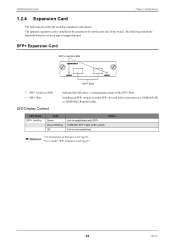
... port side of the switch. The optional expansion card is not established Status "2.2.2 Installation of Extension Card" (pg.33) Reference User's Guide " SFP+ Expansion Card" (pg.27) 25 Options SFP+ Expansion Card SFP+ Link/Act LEDs SFP+ Slots • SFP+ Link/Act LEDs • SFP+ Slots Indicated the link status / communication status of the SFP+ Slots. The following describes the available expansion card options. XG0224 Hardware Guide Chapter 1 Getting Started 1.2.4 Expansion Card The following details the functions/behaviors of each type of expansion card. LED...
... port side of the switch. The optional expansion card is not established Status "2.2.2 Installation of Extension Card" (pg.33) Reference User's Guide " SFP+ Expansion Card" (pg.27) 25 Options SFP+ Expansion Card SFP+ Link/Act LEDs SFP+ Slots • SFP+ Link/Act LEDs • SFP+ Slots Indicated the link status / communication status of the SFP+ Slots. The following describes the available expansion card options. XG0224 Hardware Guide Chapter 1 Getting Started 1.2.4 Expansion Card The following details the functions/behaviors of each type of expansion card. LED...

Hardware Guide
Page 27
... to install the switch and connect it to Console PC. 2.1 Requirements for Installation Environment 28 2.1.1 Installation Requirements 28 2.1.2 Space Requirements 30 2.2 Installation 31 2.2.1 Installation of the Switch 31 2.2.2 Installation of Extension Card 33 2.3 Connecting the Equipment 35 2.3.1 Discharging Twisted Pair Cable 35 2.3.2 Cleaning SFP Module / SFP+ Module / Optical Connector 35 2.3.3 Connecting Twisted Pair Cable / SFP Module / SFP+ Module / CX4 Cable 37 2.3.4 Installing Compact Flash Card 40 2.4 Connecting to a Setup PC 41 2.5 Time Setting 44 2.6 Set up IP address...
... to install the switch and connect it to Console PC. 2.1 Requirements for Installation Environment 28 2.1.1 Installation Requirements 28 2.1.2 Space Requirements 30 2.2 Installation 31 2.2.1 Installation of the Switch 31 2.2.2 Installation of Extension Card 33 2.3 Connecting the Equipment 35 2.3.1 Discharging Twisted Pair Cable 35 2.3.2 Cleaning SFP Module / SFP+ Module / Optical Connector 35 2.3.3 Connecting Twisted Pair Cable / SFP Module / SFP+ Module / CX4 Cable 37 2.3.4 Installing Compact Flash Card 40 2.4 Connecting to a Setup PC 41 2.5 Time Setting 44 2.6 Set up IP address...
Hardware Guide
Page 31
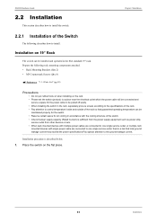
... multiple rack mounted devices with single power cable are connected to one single service outlet, there's a risk that guaranteed operating temperature can be pulled off easily. • When installing the switch in the rack, separately procure screws according to the specifications of the rack. • Pay attention to install. Prepare the following describes how to control temperature inside and outside of the switch. • Check if power supply capacity (Rated...
... multiple rack mounted devices with single power cable are connected to one single service outlet, there's a risk that guaranteed operating temperature can be pulled off easily. • When installing the switch in the rack, separately procure screws according to the specifications of the rack. • Pay attention to install. Prepare the following describes how to control temperature inside and outside of the switch. • Check if power supply capacity (Rated...
Hardware Guide
Page 35
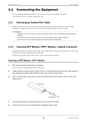
... insertion part of twisted pair cable before connecting it . Insert and slowly wheel a new cleaning stick, and dry the SFP module. 5. Also see below if dust is left. 2. Use grounded cable for power supply or buildings. • Do not short circuit with AC power supply when using static electricity removal tool, before connection. Check end face, and conduct operation below for how to install the compact flash card. 2.3.1 Discharging...
... insertion part of twisted pair cable before connecting it . Insert and slowly wheel a new cleaning stick, and dry the SFP module. 5. Also see below if dust is left. 2. Use grounded cable for power supply or buildings. • Do not short circuit with AC power supply when using static electricity removal tool, before connection. Check end face, and conduct operation below for how to install the compact flash card. 2.3.1 Discharging...
Hardware Guide
Page 37
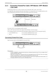
... duplex mode Connecting Twisted Pair Cable Insert twisted pair cable to connect twisted pair cable, SFP module, SFP+ module, and CX4 cable. Use straight cable when connecting with the four SFP ports. Straight cable crossing cable optical cable Port of the switch is set auto negotiation enable by default. (However, SFP+ Slots and CX4 port only support 10Gbps full duplex mode fixed setting.) Ports automatically apply to the maximum speed that are associated with routers and terminals. Their use is cabled then the associated SFP slot...
... duplex mode Connecting Twisted Pair Cable Insert twisted pair cable to connect twisted pair cable, SFP module, SFP+ module, and CX4 cable. Use straight cable when connecting with the four SFP ports. Straight cable crossing cable optical cable Port of the switch is set auto negotiation enable by default. (However, SFP+ Slots and CX4 port only support 10Gbps full duplex mode fixed setting.) Ports automatically apply to the maximum speed that are associated with routers and terminals. Their use is cabled then the associated SFP slot...
Hardware Guide
Page 41
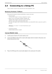
Reference User's Guide "1.1.5 Console Port Specifications" (pg.29) • Communication Software Terminal emulation software is included in this product is required to connect the set up PC to the switch. Plug in this product, and firmly fix them with the screw. 3. Confirm power of personal computer for setting up configuration is required. • RS232C crossover (null modem), D-SUB9F to D-SUB9F cable A RS232C cable is used with the RS232 cable to...
Reference User's Guide "1.1.5 Console Port Specifications" (pg.29) • Communication Software Terminal emulation software is included in this product is required to connect the set up PC to the switch. Plug in this product, and firmly fix them with the screw. 3. Confirm power of personal computer for setting up configuration is required. • RS232C crossover (null modem), D-SUB9F to D-SUB9F cable A RS232C cable is used with the RS232 cable to...
Hardware Guide
Page 43
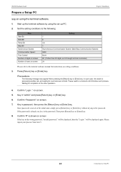
...] key. XG0224 Hardware Guide Chapter 2 Installation Prepare a Setup PC Log on using the set up PC. 2. Key in the wrong password, "invalid password." Confirm "#" is not set at the initial state, simply press [Return] key or [Enter] key without keying in the password. Please repeat your process from item 5. 43 Connecting to finish. Item Start Bit Data Bit Parity Bit Stop Bit Synchronous System Communication Speed Flow Control Number of digits on setting...
...] key. XG0224 Hardware Guide Chapter 2 Installation Prepare a Setup PC Log on using the set up PC. 2. Key in the wrong password, "invalid password." Confirm "#" is not set at the initial state, simply press [Return] key or [Enter] key without keying in the password. Please repeat your process from item 5. 43 Connecting to finish. Item Start Bit Data Bit Parity Bit Stop Bit Synchronous System Communication Speed Flow Control Number of digits on setting...
Hardware Guide
Page 46
... Screws 18 MAC Address Label 22 O Options 24 P Port Side 19 Power Cable 18 Power Inlet 22 Power Inlet Side 22 Power Requirements 28 Prepare a Setup PC 43 Product Manufacturing Label 22 PSU LED 20 R Rack Mounting Brackets 18 Ready LED 20 Redundant PSU Connector 22 Reset Switch 22 RS232C cable 41 S Safety and Installation Guide 18 SFP LED 20 SFP Link/Act LED 20 SFP Modules 24 SFP Slots 19 SFP+ Expansion Card 25 SFP+ Modules 24 Software 41 Space...
... Screws 18 MAC Address Label 22 O Options 24 P Port Side 19 Power Cable 18 Power Inlet 22 Power Inlet Side 22 Power Requirements 28 Prepare a Setup PC 43 Product Manufacturing Label 22 PSU LED 20 R Rack Mounting Brackets 18 Ready LED 20 Redundant PSU Connector 22 Reset Switch 22 RS232C cable 41 S Safety and Installation Guide 18 SFP LED 20 SFP Link/Act LED 20 SFP Modules 24 SFP Slots 19 SFP+ Expansion Card 25 SFP+ Modules 24 Software 41 Space...

