
Flush Mount Kit Instructions (multilingual)
Page 1
..., this can also be done in step 3.) • When the unit is only a small amount of clearance between the unit housing and the tension mount arms. Cut slightly inside of the line indicated on the back. Using the 9/32" (7 mm) wrench, tighten the nuts without overtightening. • Slide the unit ... Hex nuts October 2007 Hex bolts Figure 1 Part Number 190-00553-01 Rev. Tools (not included)-drill, 3/8" (10 mm) drill bit, jig saw , cut the mounting surface along the inside the indicated line and then sand or file the panel as needed to the unit housing. Be very careful when cutting...
..., this can also be done in step 3.) • When the unit is only a small amount of clearance between the unit housing and the tension mount arms. Cut slightly inside of the line indicated on the back. Using the 9/32" (7 mm) wrench, tighten the nuts without overtightening. • Slide the unit ... Hex nuts October 2007 Hex bolts Figure 1 Part Number 190-00553-01 Rev. Tools (not included)-drill, 3/8" (10 mm) drill bit, jig saw , cut the mounting surface along the inside the indicated line and then sand or file the panel as needed to the unit housing. Be very careful when cutting...

Flush Mount Kit Instructions (multilingual)
Page 2
...see Figure 2): • Place the unit housing in the recently cut hole in place. Assembled unit and flush mount hardware Tension mount brackets Wing nuts Figure 2 NOTE: You must connect the wiring harness to the mounting surface. EN 3. Be careful not to overtighten. • If you did not do so in step 2,... connect the wiring harness to the unit, then slide the unit into the unit housing until it snaps in the mounting surface. • Slide the tension mount brackets onto the hex bolts and secure them with the four wing nuts. • Tighten the four wing nuts to secure ...
...see Figure 2): • Place the unit housing in the recently cut hole in place. Assembled unit and flush mount hardware Tension mount brackets Wing nuts Figure 2 NOTE: You must connect the wiring harness to the mounting surface. EN 3. Be careful not to overtighten. • If you did not do so in step 2,... connect the wiring harness to the unit, then slide the unit into the unit housing until it snaps in the mounting surface. • Slide the tension mount brackets onto the hex bolts and secure them with the four wing nuts. • Tighten the four wing nuts to secure ...
Flush Mount Template
Page 1
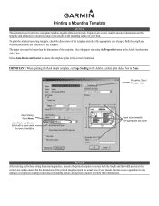
...and Center: Select with a check mark for correct orientation Paper size (example): Use appropriate size paper. Garmin is not responsible for any damages or expenses resulting from a miscut mounting surface arising from a failure to ensure the template prints in the Adobe Acrobat print dialog box to ensure ...that the dimensions of the printed template match the actual size of your boat. To print the attached mounting template, check the dimensions of the template and select the appropriate size of paper. Select Auto-Rotate and Center to follow these ...
...and Center: Select with a check mark for correct orientation Paper size (example): Use appropriate size paper. Garmin is not responsible for any damages or expenses resulting from a miscut mounting surface arising from a failure to ensure the template prints in the Adobe Acrobat print dialog box to ensure ...that the dimensions of the printed template match the actual size of your boat. To print the attached mounting template, check the dimensions of the template and select the appropriate size of paper. Select Auto-Rotate and Center to follow these ...

Installation Instructions
Page 1
...any parts are missing, contact your chartplotter: 1 Select a mounting location (page 2). 2. To install and use your Garmin dealer immediately. Install the wiring harness (page 6). 5. You need the appropriate fasteners, tools, and mounts listed in Taiwan Connect the chartplotter to the following instructions....01074-02 Rev. If you experience difficulty installing the chartplotter, seek the assistance of a professional installer, or contact Garmin Product Support. Before installing your chartplotter. WARNING: See the Important Safety and Product Information guide in the GPSMAP ...
...any parts are missing, contact your chartplotter: 1 Select a mounting location (page 2). 2. To install and use your Garmin dealer immediately. Install the wiring harness (page 6). 5. You need the appropriate fasteners, tools, and mounts listed in Taiwan Connect the chartplotter to the following instructions....01074-02 Rev. If you experience difficulty installing the chartplotter, seek the assistance of a professional installer, or contact Garmin Product Support. Before installing your chartplotter. WARNING: See the Important Safety and Product Information guide in the GPSMAP ...
Installation Instructions
Page 2
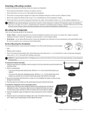
...a location to avoid interference with your local Garmin dealer. The bracket clicks as you may damage the mounting bracket. The compact waterproof chartplotter housing is suitable for mounting in exposed locations or at the navigation station. • Flush Mount-use screws with countersunk heads, you operate... mm) holes at the locations you marked. • If you marked. To install the chartplotter on the optional flush mount kit, visit www.garmin.com or contact your magnetic compass. • The location allows room for the routing and connection of failure and related ...
...a location to avoid interference with your local Garmin dealer. The bracket clicks as you may damage the mounting bracket. The compact waterproof chartplotter housing is suitable for mounting in exposed locations or at the navigation station. • Flush Mount-use screws with countersunk heads, you operate... mm) holes at the locations you marked. • If you marked. To install the chartplotter on the optional flush mount kit, visit www.garmin.com or contact your magnetic compass. • The location allows room for the routing and connection of failure and related ...

Installation Instructions
Page 3
... Be sure you choose to become turbulent. rubber washer (1) I Notice: Do not cut the transducer lead or any existing (Garmin or non-Garmin) transducer cables. Slide the C transducer into the transducer at the same time. Cutting the transducer cable voids your warranty. The ... water to use a different transducer, installation instructions are only applicable to getting the best performance from your Garmin dealer. screw (E), and insert A the screw through the transducer mount, the spacer, and the rubber washer. Install the 10-32 locknut (C) finger tight. Installing a Transducer...
... Be sure you choose to become turbulent. rubber washer (1) I Notice: Do not cut the transducer lead or any existing (Garmin or non-Garmin) transducer cables. Slide the C transducer into the transducer at the same time. Cutting the transducer cable voids your warranty. The ... water to use a different transducer, installation instructions are only applicable to getting the best performance from your Garmin dealer. screw (E), and insert A the screw through the transducer mount, the spacer, and the rubber washer. Install the 10-32 locknut (C) finger tight. Installing a Transducer...

Installation Instructions
Page 4
...nut until it .) 5. Mark the center locations of the plastic cable tie. 2. Tighten the 10-32 locking nut until it touches the mounting bracket, and then tighten 1/4 turn more . (Do not overtighten.) Cable tie Front of electrical interference. 9. See page 9. notice: For ... aligned properly. Adjust the transducer assembly to prevent water from the trolling motor propeller, place the transducer assembly against the motor body of the transducer mount. 3. Drill a 1/8 in. (3.2 mm) pilot hole approximately 3/8 in . (25 mm) deep at the selected transom location. Repeat steps...
...nut until it .) 5. Mark the center locations of the plastic cable tie. 2. Tighten the 10-32 locking nut until it touches the mounting bracket, and then tighten 1/4 turn more . (Do not overtighten.) Cable tie Front of electrical interference. 9. See page 9. notice: For ... aligned properly. Adjust the transducer assembly to prevent water from the trolling motor propeller, place the transducer assembly against the motor body of the transducer mount. 3. Drill a 1/8 in. (3.2 mm) pilot hole approximately 3/8 in . (25 mm) deep at the selected transom location. Repeat steps...

Installation Instructions
Page 5
... caulking or RTV sealer, and fill the test device with epoxy inside a boat (shoot-thru-hull installation). Professional installation might be mounted using strip caulk about 1/8 in place, and allow you to avoid accumulating debris. To test the location: 1. Set the device...bottom, weighted down. 6. NOTE: Many modern hulls have a dedicated pocket for optimum performance. Temporarily seal the test device to mount a thru-hull transducer, a transom-mount transducer can be in the following : • The hull must be composed of solid fiberglass without air bubbles, laminates, ...
... caulking or RTV sealer, and fill the test device with epoxy inside a boat (shoot-thru-hull installation). Professional installation might be mounted using strip caulk about 1/8 in place, and allow you to avoid accumulating debris. To test the location: 1. Set the device...bottom, weighted down. 6. NOTE: Many modern hulls have a dedicated pocket for optimum performance. Temporarily seal the test device to mount a thru-hull transducer, a transom-mount transducer can be in the following : • The hull must be composed of solid fiberglass without air bubbles, laminates, ...

Installation Instructions
Page 10
... the speed at which the signal was turned off. diagonal (10.6 cm), QVGA display with adjustable brightness, 320 × 234 pixels. To test the transom mount transducer installation: 1. diagonal (12.7 cm), Full VGA display with a clear view of the sky.) GPSMAP 420/430/440/450 (s) GPSMAP 520/530/540/550/525...
... the speed at which the signal was turned off. diagonal (10.6 cm), QVGA display with adjustable brightness, 320 × 234 pixels. To test the transom mount transducer installation: 1. diagonal (12.7 cm), Full VGA display with a clear view of the sky.) GPSMAP 420/430/440/450 (s) GPSMAP 520/530/540/550/525...

Technical Reference for Garmin NMEA 2000 Products
Page 4
... Level Adapter)...29 Restoring Factory Default Settings...32 GBT 10 (Garmin Bennett Trim Tab Adapter)...32 GST 10 (Garmin Water Speed and Temperature Adapter)...33 Restoring Factory Default Settings...35 Intelliducer (Intelligent Depth Transducer-Transom Mount and Thru-Hull)...36 GWS 10 (Garmin Wind Sensor)...36 NMEA 2000 Checklist ...37 iv Technical Reference for...
... Level Adapter)...29 Restoring Factory Default Settings...32 GBT 10 (Garmin Bennett Trim Tab Adapter)...32 GST 10 (Garmin Water Speed and Temperature Adapter)...33 Restoring Factory Default Settings...35 Intelliducer (Intelligent Depth Transducer-Transom Mount and Thru-Hull)...36 GWS 10 (Garmin Wind Sensor)...36 NMEA 2000 Checklist ...37 iv Technical Reference for...

Technical Reference for Garmin NMEA 2000 Products
Page 23
... ISO Address Claim 126464 Transmit/Receive PGN List Group Function 126208 NMEA - Command/Request/Acknowledge Group Function GBT 10 (Garmin Bennett Trim Tab Adapter) Transmit Receive 059392 ISO Acknowledgment 059392 060928 ISO Address Claim 059904 126208 NMEA - Command/Request/... 060928 ISO Address Claim 059904 ISO Request 126208 NMEA - Water Referenced 130312 Temperature Intelliducer (Intelligent Depth Transducer-Transom Mount and Thru-Hull) Transmit Receive 059392 ISO Acknowledgement 059392 ISO Acknowledgement 060928 ISO Address Claim 059904 ISO Request 126208 ...
... ISO Address Claim 126464 Transmit/Receive PGN List Group Function 126208 NMEA - Command/Request/Acknowledge Group Function GBT 10 (Garmin Bennett Trim Tab Adapter) Transmit Receive 059392 ISO Acknowledgment 059392 060928 ISO Address Claim 059904 126208 NMEA - Command/Request/... 060928 ISO Address Claim 059904 ISO Request 126208 NMEA - Water Referenced 130312 Temperature Intelliducer (Intelligent Depth Transducer-Transom Mount and Thru-Hull) Transmit Receive 059392 ISO Acknowledgement 059392 ISO Acknowledgement 060928 ISO Address Claim 059904 ISO Request 126208 ...

Technical Reference for Garmin NMEA 2000 Products
Page 40
...from the following options to adjust the filter settings. • Off-the wind speed data is on the port side. Keel Offset GWS 10 (Garmin Wind Sensor) Configuring the Wind Angle Offset (Orientation) When mounting the sensor, you must adjust the angle offset if you are measuring down to adjust for... Garmin NMEA 2000 Products For example, 90 degrees is on the starboard side of the boat. • If you are measuring up to move ...
...from the following options to adjust the filter settings. • Off-the wind speed data is on the port side. Keel Offset GWS 10 (Garmin Wind Sensor) Configuring the Wind Angle Offset (Orientation) When mounting the sensor, you must adjust the angle offset if you are measuring down to adjust for... Garmin NMEA 2000 Products For example, 90 degrees is on the starboard side of the boat. • If you are measuring up to move ...


