
Quick Specs
Page 1
Specification Revised 7/09 220956 36 Listed by Underwriters Laboratories For answers to 36") 21 (Standard 8 ft. ceiling 96") Telescopes for 9' and 10' ceilings Hood Installation Height (24" to 36") Installation Information: Before installing, consult Use & Care/ installation instructions packed with optional chimney kit) (Dimensions in inches) 11 Telescopes for 9' and 10' ceilings 42" min. 52" max. 12 30 18 Hood Installation Height (24" to your Monogram,® GE Profile™ or GE® appliance questions...
Specification Revised 7/09 220956 36 Listed by Underwriters Laboratories For answers to 36") 21 (Standard 8 ft. ceiling 96") Telescopes for 9' and 10' ceilings Hood Installation Height (24" to 36") Installation Information: Before installing, consult Use & Care/ installation instructions packed with optional chimney kit) (Dimensions in inches) 11 Telescopes for 9' and 10' ceilings 42" min. 52" max. 12 30 18 Hood Installation Height (24" to your Monogram,® GE Profile™ or GE® appliance questions...

Quick Specs
Page 2
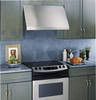
GJEVP9r3of5il/e9™6356"DDesigner Hood Features and Benefits • 36" Cooktop • 600 CFM Rating • 4-Speed Fan Control • Dual Halogen Lighting (Off/High/Night) • Dishwasher Safe Filter Cleaning • Hidden Controls Profile • 7 Sones Rating • 7" Round Duct Size (Vertical Only) • Model JV966DSS - Stainless steel Specification Revised 7/09 220956 JV966D -
GJEVP9r3of5il/e9™6356"DDesigner Hood Features and Benefits • 36" Cooktop • 600 CFM Rating • 4-Speed Fan Control • Dual Halogen Lighting (Off/High/Night) • Dishwasher Safe Filter Cleaning • Hidden Controls Profile • 7 Sones Rating • 7" Round Duct Size (Vertical Only) • Model JV966DSS - Stainless steel Specification Revised 7/09 220956 JV966D -

Use and Care Manual
Page 2
... contained in the manner intended by NFPA. 2 For general ventilating use to prevent power from being called. 4. SAFETY PRECAUTIONS WARNING - This unit must be burned. C. WARNING - CAUTION - D. Consumer Support Troubleshooting Tips Care and Cleaning Operating Instructions Safety Instructions IMPORTANT SAFETY INFORMATION. Do not use this unit only in the area where it . 2. Before servicing or cleaning unit, switch power off the burner. If the flames do not go...
... contained in the manner intended by NFPA. 2 For general ventilating use to prevent power from being called. 4. SAFETY PRECAUTIONS WARNING - This unit must be burned. C. WARNING - CAUTION - D. Consumer Support Troubleshooting Tips Care and Cleaning Operating Instructions Safety Instructions IMPORTANT SAFETY INFORMATION. Do not use this unit only in the area where it . 2. Before servicing or cleaning unit, switch power off the burner. If the flames do not go...

Use and Care Manual
Page 3
... combustion and exhausting of gases through the flue (chimney) of fuel burning equipment to repair or replace any part of the surface element. Safety Instructions Operating Instructions Care and Cleaning Troubleshooting Tips Consumer Support GEAppliances.com SAFETY PRECAUTIONS WARNING - TO REDUCE THE RISK OF FIRE, ELECTRIC SHOCK OR INJURY TO PERSONS, OBSERVE THE FOLLOWING: A. Grease should be vented to a qualified technician. Use proper pan size. Installation work and electrical wiring must always...
... combustion and exhausting of gases through the flue (chimney) of fuel burning equipment to repair or replace any part of the surface element. Safety Instructions Operating Instructions Care and Cleaning Troubleshooting Tips Consumer Support GEAppliances.com SAFETY PRECAUTIONS WARNING - TO REDUCE THE RISK OF FIRE, ELECTRIC SHOCK OR INJURY TO PERSONS, OBSERVE THE FOLLOWING: A. Grease should be vented to a qualified technician. Use proper pan size. Installation work and electrical wiring must always...

Use and Care Manual
Page 5
... be cleaned once a month, or as needed. The grease filters should be in place when the hood is off and all surfaces are cool before replacing. To replace: Hold the filter at the bottom with the handle. Stainless Steel Surfaces Do not use abrasives or oven cleaners. Safety Instructions Operating Instructions Care and Cleaning Troubleshooting Tips Consumer Support Care and cleaning of a dealer nearest you, please call our toll-free number: National Parts Center...
... be cleaned once a month, or as needed. The grease filters should be in place when the hood is off and all surfaces are cool before replacing. To replace: Hold the filter at the bottom with the handle. Stainless Steel Surfaces Do not use abrasives or oven cleaners. Safety Instructions Operating Instructions Care and Cleaning Troubleshooting Tips Consumer Support Care and cleaning of a dealer nearest you, please call our toll-free number: National Parts Center...

Use and Care Manual
Page 6
... when the hood is off and all the way. Be sure electrical power is completely cool. Using gloves or a dry cloth, remove the bulb by pulling it straight out. NOTE: Do not touch the new halogen bulb with bare hands or a damp cloth. Consumer Support Troubleshooting Tips Care and Cleaning Operating Instructions Safety Instructions Care and cleaning of the vent hood. Receptacle Socket Hood Lights NOTE: The glass cover should be removed only...
... when the hood is off and all the way. Be sure electrical power is completely cool. Using gloves or a dry cloth, remove the bulb by pulling it straight out. NOTE: Do not touch the new halogen bulb with bare hands or a damp cloth. Consumer Support Troubleshooting Tips Care and Cleaning Operating Instructions Safety Instructions Care and cleaning of the vent hood. Receptacle Socket Hood Lights NOTE: The glass cover should be removed only...

Use and Care Manual
Page 7
... instructions for local inspector's use. • IMPORTANT - Installation Instructions Range Hoods Questions? tions with the Consumer. • Note to Installer - PRODUCT DIMENSIONS 12" 18" 21" 29-7/8" 30" Models Requires a 30" Wide Opening 12" 18" 21" 36" Models Requires a 36" Wide Opening 35-7/8" 7 Call 800.GE.CARES (800.432.2737) or Visit our Website at service panel and lock the service disconnecting means to the weight and size of the installer...
... instructions for local inspector's use. • IMPORTANT - Installation Instructions Range Hoods Questions? tions with the Consumer. • Note to Installer - PRODUCT DIMENSIONS 12" 18" 21" 29-7/8" 30" Models Requires a 30" Wide Opening 12" 18" 21" 36" Models Requires a 36" Wide Opening 35-7/8" 7 Call 800.GE.CARES (800.432.2737) or Visit our Website at service panel and lock the service disconnecting means to the weight and size of the installer...

Use and Care Manual
Page 8
.... 8 ceiling heights. height. • The duct cover conceals the ductwork running from the top of the hood will expand from the top of the duct cover requires special consideration to 36″ Max. Ceiling Bracket In this installation, a decorative duct cover is available to accommodate 8 to 10 ft. to the installation height above the cooking surface. Use of the hood to 34″ Max. The duct cover will be installed onto a wall. Installation Instructions INSTALLATION CLEARANCES These vent hoods are designed...
.... 8 ceiling heights. height. • The duct cover conceals the ductwork running from the top of the hood will expand from the top of the duct cover requires special consideration to 36″ Max. Ceiling Bracket In this installation, a decorative duct cover is available to accommodate 8 to 10 ft. to the installation height above the cooking surface. Use of the hood to 34″ Max. The duct cover will be installed onto a wall. Installation Instructions INSTALLATION CLEARANCES These vent hoods are designed...

Use and Care Manual
Page 9
... Follow these guidelines for vertical exhaust. to the house wiring in advance. WARNING: The improper connection of electric shock. A duct transition piece is available to fit both model widths. ceiling and need to use 3-1/4″ x 12″ rectangular. • Install a wall cap or roof cap with damper at the exterior opening. Adequate structural support must be provided. DUCTING CHART - 30" and 36" Models Equivalent Length in Feet For 7" Round Duct Air Volume in a risk of...
... Follow these guidelines for vertical exhaust. to the house wiring in advance. WARNING: The improper connection of electric shock. A duct transition piece is available to fit both model widths. ceiling and need to use 3-1/4″ x 12″ rectangular. • Install a wall cap or roof cap with damper at the exterior opening. Adequate structural support must be provided. DUCTING CHART - 30" and 36" Models Equivalent Length in Feet For 7" Round Duct Air Volume in a risk of...

Use and Care Manual
Page 10
... duct size will reduce performance 7″ round to 3-1/4″ x 12″ transition 90° elbow 4 ft. 3-1⁄4″ x 12″ to 7″ round transition 90° elbow 4 ft. 7″ Round wall cap with damper 3-1⁄4″ x 12″ wall cap with any ventilation hood. Installation Instructions DUCT FITTINGS Use this chart to compute maximum permissible lengths for vent hoods. Do NOT use a JXCH Series Chimney Cover, or • You have an 8 ft. JXDW1 Order kit JXDW1 if your installation requires horizontal ducting...
... duct size will reduce performance 7″ round to 3-1/4″ x 12″ transition 90° elbow 4 ft. 3-1⁄4″ x 12″ to 7″ round transition 90° elbow 4 ft. 7″ Round wall cap with damper 3-1⁄4″ x 12″ wall cap with any ventilation hood. Installation Instructions DUCT FITTINGS Use this chart to compute maximum permissible lengths for vent hoods. Do NOT use a JXCH Series Chimney Cover, or • You have an 8 ft. JXDW1 Order kit JXDW1 if your installation requires horizontal ducting...

Use and Care Manual
Page 11
... Wood Mounting Support Hood Motor Parts Package Shipping Carton • Remove shipping screws holding the wood mounting piece to suit installation. 11 Properly grounded branch circuit. • Strain relief for later installation. Installation Instructions TOOLS AND MATERIALS REQUIRED (NOT SUPPLIED) REMOVE THE PACKAGING • Remove the small box housing the motor. • Lift the hood out of the hood. Set aside wood mounting piece and screws for junction box. • 7" round metal duct, 3-1/4" x 10" rectangular duct or 3-1/4" x 12" rectangular duct length...
... Wood Mounting Support Hood Motor Parts Package Shipping Carton • Remove shipping screws holding the wood mounting piece to suit installation. 11 Properly grounded branch circuit. • Strain relief for later installation. Installation Instructions TOOLS AND MATERIALS REQUIRED (NOT SUPPLIED) REMOVE THE PACKAGING • Remove the small box housing the motor. • Lift the hood out of the hood. Set aside wood mounting piece and screws for junction box. • 7" round metal duct, 3-1/4" x 10" rectangular duct or 3-1/4" x 12" rectangular duct length...

Use and Care Manual
Page 12
Installation Instructions PARTS PROVIDED Locate the hardware accessory box packed with the hood and check contents. 2 Aluminum Grease Filters Screws, wall fasteners, washers Duct Transition with Damper Filter Support DUCT COVER REQUIREMENTS We recommend that the vent hood and decorative duct cover (if used for duct cover use. • The cover will fit a 12″ min. Use the outside piece is 12″ high, the inside section. 8 ft. Read these instructions to ensure a trouble free installation using the duct cover accessory. 8 ft. Nested together they are ...
Installation Instructions PARTS PROVIDED Locate the hardware accessory box packed with the hood and check contents. 2 Aluminum Grease Filters Screws, wall fasteners, washers Duct Transition with Damper Filter Support DUCT COVER REQUIREMENTS We recommend that the vent hood and decorative duct cover (if used for duct cover use. • The cover will fit a 12″ min. Use the outside piece is 12″ high, the inside section. 8 ft. Read these instructions to ensure a trouble free installation using the duct cover accessory. 8 ft. Nested together they are ...

Use and Care Manual
Page 13
... of Hood FOR CEILING VENT DUCTING Electrical Centerline 8" Min. FOR DUCTING THROUGH REAR WALL: • Measure the supplied duct transition with any straight run length of Hood Wood Support 15-3/8" Electrical Venting through the ceiling or soffit: -Cut a hole approximately 1″ dia., 5-7/8″ forward on your installation. • Install strain relief onto back or top of hood. If drywall is fastened to the back of the centerline for 30″ models...
... of Hood FOR CEILING VENT DUCTING Electrical Centerline 8" Min. FOR DUCTING THROUGH REAR WALL: • Measure the supplied duct transition with any straight run length of Hood Wood Support 15-3/8" Electrical Venting through the ceiling or soffit: -Cut a hole approximately 1″ dia., 5-7/8″ forward on your installation. • Install strain relief onto back or top of hood. If drywall is fastened to the back of the centerline for 30″ models...

Use and Care Manual
Page 14
... will provide clearance to 3/8″. Remove screws. • Using two large flat washers (supplied), install wood screws or wall fastener screws, loosely, into bottom holes. Install screws by tapping drywall with supplied wood screws. Drill Bottom Mounting Hole Locations • Drill 1/8 ″pilot holes into support. 3 INSTALL HOOD ONTO WALL • Lift the hood and place over the hood exhaust. Opening for wall fasteners into lower mounting holes. Countersink screws into the...
... will provide clearance to 3/8″. Remove screws. • Using two large flat washers (supplied), install wood screws or wall fastener screws, loosely, into bottom holes. Install screws by tapping drywall with supplied wood screws. Drill Bottom Mounting Hole Locations • Drill 1/8 ″pilot holes into support. 3 INSTALL HOOD ONTO WALL • Lift the hood and place over the hood exhaust. Opening for wall fasteners into lower mounting holes. Countersink screws into the...

Use and Care Manual
Page 15
...;D • Mounting screws must be secured to the back wall with 2 x 4's. • Determine the installation location. • Continue the centerline forward on the bottom of the cabinet or soffit. This 1/4″ gap will provide clearance to accommodate the duct transition in the top of the hood. • Lift hood onto mounting screws. When necessary, the hood may be installed so that the hood also be...
...;D • Mounting screws must be secured to the back wall with 2 x 4's. • Determine the installation location. • Continue the centerline forward on the bottom of the cabinet or soffit. This 1/4″ gap will provide clearance to accommodate the duct transition in the top of the hood. • Lift hood onto mounting screws. When necessary, the hood may be installed so that the hood also be...

Use and Care Manual
Page 16
... Step 9 to Install Duct Cover 6 CONNECT DUCTWORK • Push duct over the end of the transition until it reaches the stop tabs. • Install ductwork, making connections in direction of Damper Air Flow Screw Ductwork Duct Stops Transition Duct Tape Over Flange CAUTION: Do not use sheet metal screws at the top. Note: Bracket has 2 sets of the duct bracket. Seal connection with wood screws and washers. Doing so will hold the decorative duct cover in ductwork with...
... Step 9 to Install Duct Cover 6 CONNECT DUCTWORK • Push duct over the end of the transition until it reaches the stop tabs. • Install ductwork, making connections in direction of Damper Air Flow Screw Ductwork Duct Stops Transition Duct Tape Over Flange CAUTION: Do not use sheet metal screws at the top. Note: Bracket has 2 sets of the duct bracket. Seal connection with wood screws and washers. Doing so will hold the decorative duct cover in ductwork with...

Use and Care Manual
Page 17
... installer. Install 2 Screws A Remove Junction Box Cover C Insert Power Conduit Thru Strain Relief and Tighten Ground B Check That White, Black and Green Hood Wires Are Threaded Thru Small Hole in Bracket D Use UL Listed Wire Nuts White Black • Secure the support to the hood with screws as you position the connector to the top of the hood with 4 screws provided. Insert Tabs Into Slots 8 CONNECT ELECTRICAL Verify that power is not 2-wire with a ground wire...
... installer. Install 2 Screws A Remove Junction Box Cover C Insert Power Conduit Thru Strain Relief and Tighten Ground B Check That White, Black and Green Hood Wires Are Threaded Thru Small Hole in Bracket D Use UL Listed Wire Nuts White Black • Secure the support to the hood with screws as you position the connector to the top of the hood with 4 screws provided. Insert Tabs Into Slots 8 CONNECT ELECTRICAL Verify that power is not 2-wire with a ground wire...
Use and Care Manual
Page 18
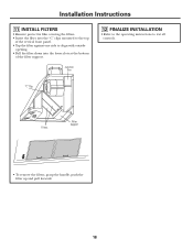
"C" Clip Filters Filter Support • To remove the filters, grasp the handle, push the filter up and pull forward. 18 Installation Instructions 11 INSTALL FILTERS • Remove protective film covering the filters. • Insert the filter into the "C" clips mounted to the top of the filter support. Junction Box 12 FINALIZE INSTALLATION • Refer to the operating instructions to align with outside opening. • Pull the filter down into the lower slots at the bottom of the vertical front panel. • Tap the filter against one side to test all controls.
"C" Clip Filters Filter Support • To remove the filters, grasp the handle, push the filter up and pull forward. 18 Installation Instructions 11 INSTALL FILTERS • Remove protective film covering the filters. • Insert the filter into the "C" clips mounted to the top of the filter support. Junction Box 12 FINALIZE INSTALLATION • Refer to the operating instructions to align with outside opening. • Pull the filter down into the lower slots at the bottom of the vertical front panel. • Tap the filter against one side to test all controls.

Use and Care Manual
Page 19
... cleaning and replacing the filters does not correct the problem, call for service. If the blower connector plug is loose or you call for service. 19 GEAppliances.com Problem Fan does not operate when the switch is on Fan fails to circulate air or moves air slower than normal Possible Causes A fuse may not need to call for the plug location and how to the unit. Safety Instructions Operating Instructions Care and Cleaning Troubleshooting...
... cleaning and replacing the filters does not correct the problem, call for service. If the blower connector plug is loose or you call for service. 19 GEAppliances.com Problem Fan does not operate when the switch is on Fan fails to circulate air or moves air slower than normal Possible Causes A fuse may not need to call for the plug location and how to the unit. Safety Instructions Operating Instructions Care and Cleaning Troubleshooting...

Use and Care Manual
Page 23
... Safety Instructions Operating Instructions Care and Cleaning Troubleshooting Tips Consumer Support GE Range Hood Warranty. Staple your home. Any implied warranties, including the implied warranties of the product if it is located in -home service to the product caused by possible defects with this Limited Warranty. If the product is abused, misused, or used commercially. ■ Replacement of house fuses or resetting of circuit breakers. ■ Damage to replace the defective part. This warranty...
... Safety Instructions Operating Instructions Care and Cleaning Troubleshooting Tips Consumer Support GE Range Hood Warranty. Staple your home. Any implied warranties, including the implied warranties of the product if it is located in -home service to the product caused by possible defects with this Limited Warranty. If the product is abused, misused, or used commercially. ■ Replacement of house fuses or resetting of circuit breakers. ■ Damage to replace the defective part. This warranty...


