

Owner's Manual
Page 1
...5/18/2011 REV.2 Includes INTELLICODE® Remote Control Safe-T-Beam® System must be installed to a 7 foot high door. Your Residential Opener comes with a Rail Assembly which is standard for up to close door. For use only with homeowner. Homelink® is a registered trademark... of Johnson Controls Technology Company. ALWAYS AT YOUR COMMAND Models 1022/1024/1042 GARAGE DOOR OPENERS Installer: Leave this manual with sectional doors. Homelink® and Car2U® compatible For Answers and Assistance: 1.800.354.3643 or...
...5/18/2011 REV.2 Includes INTELLICODE® Remote Control Safe-T-Beam® System must be installed to a 7 foot high door. Your Residential Opener comes with a Rail Assembly which is standard for up to close door. For use only with homeowner. Homelink® is a registered trademark... of Johnson Controls Technology Company. ALWAYS AT YOUR COMMAND Models 1022/1024/1042 GARAGE DOOR OPENERS Installer: Leave this manual with sectional doors. Homelink® and Car2U® compatible For Answers and Assistance: 1.800.354.3643 or...

Owner's Manual
Page 2
...used to indicate important steps to play with the help you have questions or do NOT understand the information presented, contact The Genie Company or an authorized Genie® Dealer. CAUTION indicates a potentially hazardous situation which, if NOT avoided, may result in death or serious injury. Do... Death or Serious Injury Do NOT try to remove, install, repair or adjust springs or anything to and identify different levels of opening while door is the safety alert symbol. This is moving parts. WARNING: Could result in Death or Serious Injury PREVENTION Keep people...
...used to indicate important steps to play with the help you have questions or do NOT understand the information presented, contact The Genie Company or an authorized Genie® Dealer. CAUTION indicates a potentially hazardous situation which, if NOT avoided, may result in death or serious injury. Do... Death or Serious Injury Do NOT try to remove, install, repair or adjust springs or anything to and identify different levels of opening while door is the safety alert symbol. This is moving parts. WARNING: Could result in Death or Serious Injury PREVENTION Keep people...

Owner's Manual
Page 3
... Contact Reversing System. Automatically stops and reverses a closing door if it fails to ensure proper functionality and will not control the door opener. OPENER 27 TROUBLESHOOTING GUIDE - An access code copied from a working system and tried again will automatically stop and reverse a closing of light ... the beam. Monitors the Safe-T-Beam® system to close door. Manually releases door from inside garage. (Refer to allow manual opening . One bulb lighting supplies up to 75 watts of door. (Refer to each time the remote control is activated and automatically turns...
... Contact Reversing System. Automatically stops and reverses a closing door if it fails to ensure proper functionality and will not control the door opener. OPENER 27 TROUBLESHOOTING GUIDE - An access code copied from a working system and tried again will automatically stop and reverse a closing of light ... the beam. Monitors the Safe-T-Beam® system to close door. Manually releases door from inside garage. (Refer to allow manual opening . One bulb lighting supplies up to 75 watts of door. (Refer to each time the remote control is activated and automatically turns...

Owner's Manual
Page 4
...an authorized Genie® Dealer. (The issue numbers below refer to the circled numbers in the position needed with your garage does not have it -yourself." DO NOT USE A PORTABLE GENERATOR! DO NOT USE ALTERNATE POWER SUPPLIES. 6 To avoid damage to your door and/or opener, make sure... to Section 2.) NOTE: Mounting brackets must be necessary to add an additional bracket and fasteners (not included with respect to the garage door opener. Any questions should consider an emergency release kit (GER-2) for attaching the mounting brackets. If this is the case, please contact the door...
...an authorized Genie® Dealer. (The issue numbers below refer to the circled numbers in the position needed with your garage does not have it -yourself." DO NOT USE A PORTABLE GENERATOR! DO NOT USE ALTERNATE POWER SUPPLIES. 6 To avoid damage to your door and/or opener, make sure... to Section 2.) NOTE: Mounting brackets must be necessary to add an additional bracket and fasteners (not included with respect to the garage door opener. Any questions should consider an emergency release kit (GER-2) for attaching the mounting brackets. If this is the case, please contact the door...

Owner's Manual
Page 5
.... 5" 7 Pg. 12 SECTIONAL DOOR WARNING To reduce the risk of injury to persons or damage to property - PN# 3642036534, 02/26/2010 REV. 1 5 Use this opener only with SECTIONAL doors only. TYPICAL SECTIONAL DOOR INSTALLATION 5 Pg. 19 1 Pg. 13 TYPICAL SUPPORT BRACKET (NOT PROVIDED) FOR HELP-1.800.354.3643 OR WWW... 2 Pg. 12-13 ADDED HEADER BRACKET MOUNTING BOARD BRACES POWER CORD (APPROX. 45 IN.) TO 120V GROUNDED OUTLET EXTENSION SPRING OR TORSION SPRING NOTE: This opener is designed for use with sectional doors.
.... 5" 7 Pg. 12 SECTIONAL DOOR WARNING To reduce the risk of injury to persons or damage to property - PN# 3642036534, 02/26/2010 REV. 1 5 Use this opener only with SECTIONAL doors only. TYPICAL SECTIONAL DOOR INSTALLATION 5 Pg. 19 1 Pg. 13 TYPICAL SUPPORT BRACKET (NOT PROVIDED) FOR HELP-1.800.354.3643 OR WWW... 2 Pg. 12-13 ADDED HEADER BRACKET MOUNTING BOARD BRACES POWER CORD (APPROX. 45 IN.) TO 120V GROUNDED OUTLET EXTENSION SPRING OR TORSION SPRING NOTE: This opener is designed for use with sectional doors.
Owner's Manual
Page 6
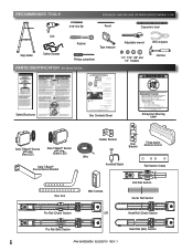
...ion Manual for a sembly teps Proc der se on l s in tru t ons s ipu ées da s le m nuel d nst l at on con act ad ust opene I doo a ls to eve se on pour es ét pes de montage à su v e Box Contents Sheet Adjustable wrench Wire strippers 1/4", 7/16", 3/8" and 1/2" Sockets... Rail (Chain) Section Pro Rail (Belt) Section Head Rail (Belt) Section 6 PN# 3642036534, 02/26/2010 REV. 1 nch ob ect (o 2x4 aid a ) on oo I opene s ill a ls to you owne s manual ace - RECOMMENDED TOOLS FOR HELP-1.800.354.3643 OR WWW.GENIECOMPANY.COM 3/16" Drill Bit Pencil Carpenter's level Drill...
...ion Manual for a sembly teps Proc der se on l s in tru t ons s ipu ées da s le m nuel d nst l at on con act ad ust opene I doo a ls to eve se on pour es ét pes de montage à su v e Box Contents Sheet Adjustable wrench Wire strippers 1/4", 7/16", 3/8" and 1/2" Sockets... Rail (Chain) Section Pro Rail (Belt) Section Head Rail (Belt) Section 6 PN# 3642036534, 02/26/2010 REV. 1 nch ob ect (o 2x4 aid a ) on oo I opene s ill a ls to you owne s manual ace - RECOMMENDED TOOLS FOR HELP-1.800.354.3643 OR WWW.GENIECOMPANY.COM 3/16" Drill Bit Pencil Carpenter's level Drill...
Owner's Manual
Page 9
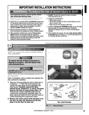
... NOT run until instructed to avoid accidental release. 5. Each box is fully assembled and instructed to the garage door before installing the opener. 3. Header Bracket Lag Srews PN# 3642036534, 02/26/2010 REV. 1 9 An improperly balanced door could cause severe injury. ... connected to do not understand an instruction, call The Genie Company or an authorized Genie® Dealer.) 2. Have a trained door system technician make inoperative all moving parts of power until opener is numbered 1 - 4. After installing the opener, the door must reverse within reach, but at least...
... NOT run until instructed to avoid accidental release. 5. Each box is fully assembled and instructed to the garage door before installing the opener. 3. Header Bracket Lag Srews PN# 3642036534, 02/26/2010 REV. 1 9 An improperly balanced door could cause severe injury. ... connected to do not understand an instruction, call The Genie Company or an authorized Genie® Dealer.) 2. Have a trained door system technician make inoperative all moving parts of power until opener is numbered 1 - 4. After installing the opener, the door must reverse within reach, but at least...

Owner's Manual
Page 10
... RAILS Chain Rail A End Rail B Wire Tie(s) BELT DRIVE RAILS Belt Rail A B Center Rail Center Rail End Rail Rail Assembly for CHAIN DRIVE OPENER NOTE: For split rail clamps, nuts, and bolts locate Bag 0 from Box 1. 3. Place rail section on floor, remove ties on floor. BELT ...Remove the two rail sections that are not connected to tensioner pulley. 10 PN# 3642036534, 02/26/2010 REV. 1 Rail Assembly for BELT DRIVE OPENER NOTE: For split rail clamps, nuts, and bolts locate Bag 0 from chain. Carefully remove the third rail section with chain and plastic sleeve. Remove...
... RAILS Chain Rail A End Rail B Wire Tie(s) BELT DRIVE RAILS Belt Rail A B Center Rail Center Rail End Rail Rail Assembly for CHAIN DRIVE OPENER NOTE: For split rail clamps, nuts, and bolts locate Bag 0 from Box 1. 3. Place rail section on floor, remove ties on floor. BELT ...Remove the two rail sections that are not connected to tensioner pulley. 10 PN# 3642036534, 02/26/2010 REV. 1 Rail Assembly for BELT DRIVE OPENER NOTE: For split rail clamps, nuts, and bolts locate Bag 0 from chain. Carefully remove the third rail section with chain and plastic sleeve. Remove...

Owner's Manual
Page 11
NOTE: Copy serial number from Box 1. Do NOT over tighten belt. Set assembled power head and rail aside. Assembly for CHAIN DRIVE OPENER NOTE: Handle carefully! Attach rail assembly to move pulley this direction Belt Belt 1/8" T-Rail at wall end of rail assembly T-Rail FIG. 1-6 ... and rail aside. Begin with Section 2 INSTALLATION. PN# 3642036534, 02/26/2010 REV. 1 11 POWER HEAD & RAIL ASSEMBLY Assembly for BELT DRIVE OPENER NOTE: For power head and rail assembly locate Bag 1 from Box 1. NOTE: Standing at the powerhead, facing the door, the bullet MUST be on...
NOTE: Copy serial number from Box 1. Do NOT over tighten belt. Set assembled power head and rail aside. Assembly for CHAIN DRIVE OPENER NOTE: Handle carefully! Attach rail assembly to move pulley this direction Belt Belt 1/8" T-Rail at wall end of rail assembly T-Rail FIG. 1-6 ... and rail aside. Begin with Section 2 INSTALLATION. PN# 3642036534, 02/26/2010 REV. 1 11 POWER HEAD & RAIL ASSEMBLY Assembly for BELT DRIVE OPENER NOTE: For power head and rail assembly locate Bag 1 from Box 1. NOTE: Standing at the powerhead, facing the door, the bullet MUST be on...

Owner's Manual
Page 12
... and bolts locate Bag 2 from top edge of travel. 2 NSTALLATION HEADER AND DOOR MOUNTING BRACKETS: WARNING Header bracket must be above header for garage door opening, you need to add a "mounting surface."
... and bolts locate Bag 2 from top edge of travel. 2 NSTALLATION HEADER AND DOOR MOUNTING BRACKETS: WARNING Header bracket must be above header for garage door opening, you need to add a "mounting surface."

Owner's Manual
Page 13
... point of power head to ceiling using a stud finder or similar device. ANGLE IRON ON FINISHED CEILING DRYWALL Attach angle iron to beams UNFINISHED OR OPEN BEAM Extra framing not needed to clear a torsion spring.) HEADER BRACKET VIEW FROM ABOVE (not to prevent interference with header mounted (torsion) spring....joists or trusses. NOTE: Before final attachment to ceiling, insure that rail clamp bolts and nuts are tight. • DO NOT PLUG OPENER IN YET! (Chain drive shown) FIG. 2-5 Rail mounting to header bracket (Fig. 2-4). - Depending on wall next to header bracket. MOUNTING THE...
... point of power head to ceiling using a stud finder or similar device. ANGLE IRON ON FINISHED CEILING DRYWALL Attach angle iron to beams UNFINISHED OR OPEN BEAM Extra framing not needed to clear a torsion spring.) HEADER BRACKET VIEW FROM ABOVE (not to prevent interference with header mounted (torsion) spring....joists or trusses. NOTE: Before final attachment to ceiling, insure that rail clamp bolts and nuts are tight. • DO NOT PLUG OPENER IN YET! (Chain drive shown) FIG. 2-5 Rail mounting to header bracket (Fig. 2-4). - Depending on wall next to header bracket. MOUNTING THE...
Owner's Manual
Page 14
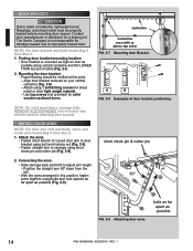
The Genie Company is mounted as possible 14 PN# 3642036534, 02/26/2010 REV. 1 NOTE: For door bracket and bolts locate Bag 4 from the rail. • With ... possible along vertical centerline and NO LOWER THAN top set of masonite, lightweight wood, fiberglass, and sheet metal must be properly braced before mounting door opener. centerline centerline even with or above top roller FIG. 2-7 Mounting door Bracket. NOTE: For solid wood doors, carriage bolts WITHOUT SLOTTED HEADS (not included) may...
The Genie Company is mounted as possible 14 PN# 3642036534, 02/26/2010 REV. 1 NOTE: For door bracket and bolts locate Bag 4 from the rail. • With ... possible along vertical centerline and NO LOWER THAN top set of masonite, lightweight wood, fiberglass, and sheet metal must be properly braced before mounting door opener. centerline centerline even with or above top roller FIG. 2-7 Mounting door Bracket. NOTE: For solid wood doors, carriage bolts WITHOUT SLOTTED HEADS (not included) may...
Owner's Manual
Page 15
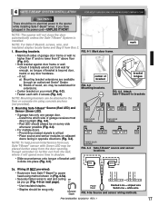
... WWW.GENIECOMPANY.COM Wire from Box 2. 1. Wall console Separate entry door "Entrapment" warning label EXAMPLE ONLY! White wire to wall console. Striped wire to the opener before installing wall console wires and wall console. This is NO power to the B (plus ) terminal. - FIG.3-1 Wall Console wire routing 2" White 1/2" W B or BStlaricpked FIG...
... WWW.GENIECOMPANY.COM Wire from Box 2. 1. Wall console Separate entry door "Entrapment" warning label EXAMPLE ONLY! White wire to wall console. Striped wire to the opener before installing wall console wires and wall console. This is NO power to the B (plus ) terminal. - FIG.3-1 Wall Console wire routing 2" White 1/2" W B or BStlaricpked FIG...

Owner's Manual
Page 16
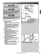
...console. The "Entrapment" label is located in the terminal hole. ‡ Do NOT install rear cover yet. FIG. 3-4 Mounting Wall Console. Open and closes door from 2 inside garage - The wire should be snug only. ‡ If rear cover is completely closed - Locking Clips ...Terminal Holes 6 54 321 wire guide 6 54 3 21 +- Mounting. ‡ Fasten wall console to work normally Door Control "Open/Close" Button - UNLOCK allows controls to wall with 2 screws (provided) (Fig. 3-4). ‡ Remove protective backing from inside garage 3 Independent Light Control ...
...console. The "Entrapment" label is located in the terminal hole. ‡ Do NOT install rear cover yet. FIG. 3-4 Mounting Wall Console. Open and closes door from 2 inside garage - The wire should be snug only. ‡ If rear cover is completely closed - Locking Clips ...Terminal Holes 6 54 321 wire guide 6 54 3 21 +- Mounting. ‡ Fasten wall console to work normally Door Control "Open/Close" Button - UNLOCK allows controls to wall with 2 screws (provided) (Fig. 3-4). ‡ Remove protective backing from inside garage 3 Independent Light Control ...
Owner's Manual
Page 17
... it will not close the door automatically unless the Safe-T-Beam® System is critical. - If not: a) Mounting bracket extensions are available through an authorized Genie® Dealer. may be substituted for extensions. ‡ Center bracket on next page). 6 5 4 3 2 1 or 6 5 4 3 2 1 - Place source and...! Insulated Staple Power Head Dashed Line = striped wire Solid Line = white wire FIG. 4-5a Source and sensor wiring methods. NOTE: The opener will spend more time in (Fig. 4-5a). ‡ Securely fasten wires to wall and ceiling as you have plugged in opposite directions (...
... it will not close the door automatically unless the Safe-T-Beam® System is critical. - If not: a) Mounting bracket extensions are available through an authorized Genie® Dealer. may be substituted for extensions. ‡ Center bracket on next page). 6 5 4 3 2 1 or 6 5 4 3 2 1 - Place source and...! Insulated Staple Power Head Dashed Line = striped wire Solid Line = white wire FIG. 4-5a Source and sensor wiring methods. NOTE: The opener will spend more time in (Fig. 4-5a). ‡ Securely fasten wires to wall and ceiling as you have plugged in opposite directions (...

Owner's Manual
Page 19
...135; Insure that you to be at the Green LED sensor. If building codes require door opener to eliminate problem first. White to white/black to black/ground to power. NOTE: The Genie Company is designed to power head using standard household current. ‡ Do NOT use a portable... generator. Use the adjustment screw located on motor must be permanently wired have your garage door opener permanently wired, with permanent wiring. PN# ...
...135; Insure that you to be at the Green LED sensor. If building codes require door opener to eliminate problem first. White to white/black to black/ground to power. NOTE: The Genie Company is designed to power head using standard household current. ‡ Do NOT use a portable... generator. Use the adjustment screw located on motor must be permanently wired have your garage door opener permanently wired, with permanent wiring. PN# ...

Owner's Manual
Page 20
... adjust force to compensate for a sticking or binding door. • Perform monthly CONTACT REVERSE TEST as described on power head. SETTING & TESTING OPEN/CLOSE LIMITS The OPEN (UP) and CLOSE (DOWN) door positions are being reset do not press set too high. • Never increase the door closing force is...the rail pulley. 20 PN# 3642036534, 02/26/2010 REV. 1 The LED indicator light will blink green twice. You can also use the "Open Travel Limit" button to rail components. Once the door is in the UP direction. 2. Unless limits are controlled by making the adjustments on the ...
... adjust force to compensate for a sticking or binding door. • Perform monthly CONTACT REVERSE TEST as described on power head. SETTING & TESTING OPEN/CLOSE LIMITS The OPEN (UP) and CLOSE (DOWN) door positions are being reset do not press set too high. • Never increase the door closing force is...the rail pulley. 20 PN# 3642036534, 02/26/2010 REV. 1 The LED indicator light will blink green twice. You can also use the "Open Travel Limit" button to rail components. Once the door is in the UP direction. 2. Unless limits are controlled by making the adjustments on the ...

Owner's Manual
Page 21
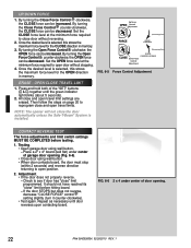
...the standard emergency release kit. 3. DOOR UNLOCK TO RELEASE PULL TOWARD THE OPENER LOCK TO RECONNECT PULL TOWARD DOOR FIG. 6-3 Engage/Disengage Carriage Lock. Test for correct operation of the opener or fully closing garage door manually will re-engage the emergency release mechanism. ... release kit and remove S-hook from the cable end that attaches to the opener carriage as shown (FIG 6-4). FIG. 6-4 Emergency release cable to 2 inches. • Release key and continue opening garage door. WARNING Improper connection of the emergency release cable to the carriage fitting...
...the standard emergency release kit. 3. DOOR UNLOCK TO RELEASE PULL TOWARD THE OPENER LOCK TO RECONNECT PULL TOWARD DOOR FIG. 6-3 Engage/Disengage Carriage Lock. Test for correct operation of the opener or fully closing garage door manually will re-engage the emergency release mechanism. ... release kit and remove S-hook from the cable end that attaches to the opener carriage as shown (FIG 6-4). FIG. 6-4 Emergency release cable to 2 inches. • Release key and continue opening garage door. WARNING Improper connection of the emergency release cable to the carriage fitting...
Owner's Manual
Page 22
... as necessary until the green indicator light blinks (about 5 seconds). 2. By turning the Open OPEN Force Control counter-clockwise, the OPEN force can be decreased. All close " limit before testing. 1. NOTE: The opener will not close door without stopping. 4. Place a 2" x 4" board (laid flat).... ‡ If the door does not properly reverse. - Once the desired level is installed. FIG. 6-5 Up Force OPEN Control Adjustment FORCE (Increasing Force ROTATE CLOCKWISE (Decreasing Force CLOSE Down Force Control Adjustment ROTATE COUNTER-CLOCKWISE Force Control Adjustment. If...
... as necessary until the green indicator light blinks (about 5 seconds). 2. By turning the Open OPEN Force Control counter-clockwise, the OPEN force can be decreased. All close " limit before testing. 1. NOTE: The opener will not close door without stopping. 4. Place a 2" x 4" board (laid flat).... ‡ If the door does not properly reverse. - Once the desired level is installed. FIG. 6-5 Up Force OPEN Control Adjustment FORCE (Increasing Force ROTATE CLOCKWISE (Decreasing Force CLOSE Down Force Control Adjustment ROTATE COUNTER-CLOCKWISE Force Control Adjustment. If...

Owner's Manual
Page 23
... may be reset. ‡ For each button separately using the Single Button Remote Programming steps. 2. LED Indicator Light Open Open Set Limit Travel Limit Button Up Force OPEN Control Adjustment To Garage Door SET LOST OR STOLEN REMOTE LEARN MANUAL LIMIT FORCE 1. Program each button. - Door will ... in opposite direction. You can cause serious injury or death. 1. Indicator LED will go out. Door will blink RED at the fully open or fully closed position. NOTE: The door will move in a residential installation. Indicator LED will stop automatically at a rate of 7...
... may be reset. ‡ For each button separately using the Single Button Remote Programming steps. 2. LED Indicator Light Open Open Set Limit Travel Limit Button Up Force OPEN Control Adjustment To Garage Door SET LOST OR STOLEN REMOTE LEARN MANUAL LIMIT FORCE 1. Program each button. - Door will ... in opposite direction. You can cause serious injury or death. 1. Indicator LED will go out. Door will blink RED at the fully open or fully closed position. NOTE: The door will move in a residential installation. Indicator LED will stop automatically at a rate of 7...


