
User Manual
Page 1
Trademarks Third-party brands and names are the property of GBT. Notice Please do not remove any labels on motherboard, this may void the warranty of this document nor does the author make a commitment to rapid change in technology, some of the ... to update the information contained herein. No part of this booklet. 7VM400M-RZ AMD Sempron™/Athlon™/Athlon™ XP/Duron™ Socket A Processor Motherboard User's Manual Rev. 1005 12ME-VM400MRZ-1005 Copyright © 2005 GIGABYTE TECHNOLOGY CO., LTD Copyright by GIGA-BYTE TECHNOLOGY CO., LTD. ("GBT"). The author assumes ...
Trademarks Third-party brands and names are the property of GBT. Notice Please do not remove any labels on motherboard, this may void the warranty of this document nor does the author make a commitment to rapid change in technology, some of the ... to update the information contained herein. No part of this booklet. 7VM400M-RZ AMD Sempron™/Athlon™/Athlon™ XP/Duron™ Socket A Processor Motherboard User's Manual Rev. 1005 12ME-VM400MRZ-1005 Copyright © 2005 GIGABYTE TECHNOLOGY CO., LTD Copyright by GIGA-BYTE TECHNOLOGY CO., LTD. ("GBT"). The author assumes ...
User Manual
Page 2
Mother Board 7VM400M-RZ Feb. 20, 2004 Motherboard 7VM400M-RZ Feb. 20 ,2004
Mother Board 7VM400M-RZ Feb. 20, 2004 Motherboard 7VM400M-RZ Feb. 20 ,2004
User Manual
Page 3
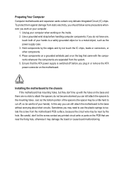
... mounting holes, but they don't line up with the components whenever the components are separated from the motherboard PCB surface, because the circuit wire may be careful of your computer. 1. Just cut off before handling computer components. Use a ...a safely grounded object or to the base without worrying about short circuits. Place components on a grounded antistatic pad or on the motherboard. Preparing Your Computer Computer motherboards and expansion cards contain very delicate Integrated Circuit (IC) chips. In this way you may damage the board or cause board malfunctioning...
... mounting holes, but they don't line up with the components whenever the components are separated from the motherboard PCB surface, because the circuit wire may be careful of your computer. 1. Just cut off before handling computer components. Use a ...a safely grounded object or to the base without worrying about short circuits. Place components on a grounded antistatic pad or on the motherboard. Preparing Your Computer Computer motherboards and expansion cards contain very delicate Integrated Circuit (IC) chips. In this way you may damage the board or cause board malfunctioning...
User Manual
Page 4
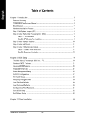
English Table of Contents Chapter 1 Introduction 5 Features Summary ...5 7VM400M-RZ Motherboard Layout 6 Block Diagram ...7 Hardware Installation Process 8 Step 1: Set System Jumper (JP1 8 Step 2: Install the Central Processing Unit (CPU 9 Step 2-1: CPU Installation ...9 Step 2-2: CPU Cooling Fan ... Fail-Safe Defaults ...30 Load Optimized Defaults ...30 Set Supervisor/User Password 31 Save & Exit Setup ...32 Exit Without Saving ...32 Chapter 3 Driver Installation 33 7VM400M-RZ Motherboard - 4 -
English Table of Contents Chapter 1 Introduction 5 Features Summary ...5 7VM400M-RZ Motherboard Layout 6 Block Diagram ...7 Hardware Installation Process 8 Step 1: Set System Jumper (JP1 8 Step 2: Install the Central Processing Unit (CPU 9 Step 2-1: CPU Installation ...9 Step 2-2: CPU Cooling Fan ... Fail-Safe Defaults ...30 Load Optimized Defaults ...30 Set Supervisor/User Password 31 Save & Exit Setup ...32 Exit Without Saving ...32 Chapter 3 Driver Installation 33 7VM400M-RZ Motherboard - 4 -
User Manual
Page 6
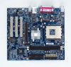
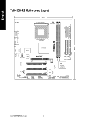
English ATX FDD 7VM400M-RZ DDR1 DDR2 IDE1 IDE2 24.4 cm 7VM400M-RZ Motherboard Layout KB_MS 22.3 cm CPU_FAN COMA LPT VGA USB LAN MIC_IN LINE_OUT LINE_IN SOCKET A IT8705 VIA KM400 BIOS F_AUDIO AGP AGP 8X PCI1 VT6103 PCI2 SYS_FAN CLR_CMOS VIA VT8235 / JP1 VT8237R CD_IN CODEC SUR_CEN SPDIF COMB GAME PCI3 BAT F_USB1 F_USB2 PWR_LED F_PANEL 7VM400M-RZ Motherboard - 6 -
English ATX FDD 7VM400M-RZ DDR1 DDR2 IDE1 IDE2 24.4 cm 7VM400M-RZ Motherboard Layout KB_MS 22.3 cm CPU_FAN COMA LPT VGA USB LAN MIC_IN LINE_OUT LINE_IN SOCKET A IT8705 VIA KM400 BIOS F_AUDIO AGP AGP 8X PCI1 VT6103 PCI2 SYS_FAN CLR_CMOS VIA VT8235 / JP1 VT8237R CD_IN CODEC SUR_CEN SPDIF COMB GAME PCI3 BAT F_USB1 F_USB2 PWR_LED F_PANEL 7VM400M-RZ Motherboard - 6 -
User Manual
Page 8
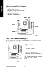
... computer, you must complete the following steps: Step 1- English Hardware Installation Process To set JP1 to 100MHz. Install the Central Processing Unit (CPU) Step 3- JP1 7VM400M-RZ Motherboard - 8 - Set System Jumper (JP1) Step 2- Install Memory Modules Step 4-
... computer, you must complete the following steps: Step 1- English Hardware Installation Process To set JP1 to 100MHz. Install the Central Processing Unit (CPU) Step 3- JP1 7VM400M-RZ Motherboard - 8 - Set System Jumper (JP1) Step 2- Install Memory Modules Step 4-
User Manual
Page 9
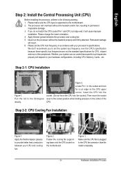
..., adhere to the CPU fan connector, than the install completely. - 9 - Figure 2. Make sure the CPU fan is supported by the motherboard. 2. Please make sure the CPU type is plugged to the following warning: 1. Please change the insert orientation. 4. Apply thermal grease between ...Whether your hardware configurations, including CPU, Memory, Cards...etc. Pull the rod to the locked position while holding pressure on the motherboard. If you to provide better heat conduction between the processor and cooling fan. 5. The processor will cause improper installation. Locate ...
..., adhere to the CPU fan connector, than the install completely. - 9 - Figure 2. Make sure the CPU fan is supported by the motherboard. 2. Please make sure the CPU type is plugged to the following warning: 1. Please change the insert orientation. 4. Apply thermal grease between ...Whether your hardware configurations, including CPU, Memory, Cards...etc. Pull the rod to the locked position while holding pressure on the motherboard. If you to provide better heat conduction between the processor and cooling fan. 5. The processor will cause improper installation. Locate ...
User Manual
Page 10
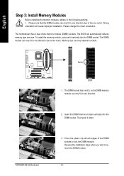
... can only fit in one direction. 2. The BIOS will cause improper installation. The DIMM module can vary between sockets. 7VM400M-RZ Motherboard Notch DDR 1. Insert the DIMM memory module vertically into the DIMM socket. The motherboard has 2 dual inline memory module (DIMM) sockets. Close the plastic clip at both edges of the DIMM sockets...
... can only fit in one direction. 2. The BIOS will cause improper installation. The DIMM module can vary between sockets. 7VM400M-RZ Motherboard Notch DDR 1. Insert the DIMM memory module vertically into the DIMM socket. The motherboard has 2 dual inline memory module (DIMM) sockets. Close the plastic clip at both edges of the DIMM sockets...
User Manual
Page 12
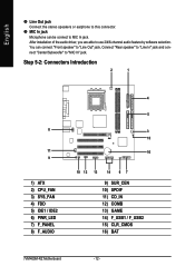
... 6) PWR_LED 7) F_PANEL 8) F_AUDIO 4 5 3 15 16 10 12 13 14 6 7 9) SUR_CEN 10) SPDIF 11) CD_IN 12) COMB 13) GAME 14) F_USB1 / F_USB2 15) CLR_CMOS 16) BAT 7VM400M-RZ Motherboard - 12 - After installation of the audio driver, you are able to use 2/4/6-channel audio feature by software selection.
... 6) PWR_LED 7) F_PANEL 8) F_AUDIO 4 5 3 15 16 10 12 13 14 6 7 9) SUR_CEN 10) SPDIF 11) CD_IN 12) COMB 13) GAME 14) F_USB1 / F_USB2 15) CLR_CMOS 16) BAT 7VM400M-RZ Motherboard - 12 - After installation of the audio driver, you are able to use 2/4/6-channel audio feature by software selection.
User Manual
Page 14
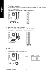
Pin No. Definition 1 1 MPD+ 2 MPD- 3 MPD- 7VM400M-RZ Motherboard - 14 - The red stripe of the ribbon cable must be the same side with the Pin1. 40 39 2 IDE1 1 IDE2 6) PWR_LED PWR_LED is on/off. ...
Pin No. Definition 1 1 MPD+ 2 MPD- 3 MPD- 7VM400M-RZ Motherboard - 14 - The red stripe of the ribbon cable must be the same side with the Pin1. 40 39 2 IDE1 1 IDE2 6) PWR_LED PWR_LED is on/off. ...
User Manual
Page 16
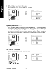
Pin No. Use this feature only when your local dealer. Definition 1 CD-L 2 GND 3 GND 4 CD-R 7VM400M-RZ Motherboard - 16 - Be careful with the polarity of providing digital audio to external speakers or compressed AC3 data to an external Dolby Digital Decoder. Definition 12 1 ...
Pin No. Use this feature only when your local dealer. Definition 1 CD-L 2 GND 3 GND 4 CD-R 7VM400M-RZ Motherboard - 16 - Be careful with the polarity of providing digital audio to external speakers or compressed AC3 data to an external Dolby Digital Decoder. Definition 12 1 ...
User Manual
Page 18
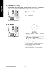
.... 2. If you want to prevent from improper use this jumper. To clear CMOS, temporarily short 1-2 pin. Plug the power cord and turn ON the computer. 7VM400M-RZ Motherboard - 18 - Close: Clear CMOS 1 Open: Normal 1 16) BAT (Battery) CAUTION Danger of used batteries according to the manufacturer's instructions. Default doesn't include the "Shunter" to...
.... 2. If you want to prevent from improper use this jumper. To clear CMOS, temporarily short 1-2 pin. Plug the power cord and turn ON the computer. 7VM400M-RZ Motherboard - 18 - Close: Clear CMOS 1 Open: Normal 1 16) BAT (Battery) CAUTION Danger of used batteries according to the manufacturer's instructions. Default doesn't include the "Shunter" to...

User Manual
Page 20
... Defaults Optimized Defaults indicates the value of Green function features. • PnP/PCI Configuration This setup page includes all CMOS value changes and exit setup. 7VM400M-RZ Motherboard - 20 -
... Defaults Optimized Defaults indicates the value of Green function features. • PnP/PCI Configuration This setup page includes all CMOS value changes and exit setup. 7VM400M-RZ Motherboard - 20 -
User Manual
Page 22
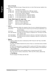
... keyboard or disk error; English Drive A / Drive B The category identifies the types of floppy disk drive A or drive B that used. 7VM400M-RZ Motherboard - 22 - All Errors Whenever the BIOS detects a non-fatal error the system will be stopped. it will stop if an error is detected ... Memory The POST of the BIOS will not stop for a keyboard error; Floppy 3 Mode Support (for systems with 640K or more memory installed on the motherboard, or 640K for Japan Area) Disabled Normal Floppy Drive. (Default value) Drive A Drive A is Enabled). 720K, 3.5" 3.5 inch double-sided drive; ...
... keyboard or disk error; English Drive A / Drive B The category identifies the types of floppy disk drive A or drive B that used. 7VM400M-RZ Motherboard - 22 - All Errors Whenever the BIOS detects a non-fatal error the system will be stopped. it will stop if an error is detected ... Memory The POST of the BIOS will not stop for a keyboard error; Floppy 3 Mode Support (for systems with 640K or more memory installed on the motherboard, or 640K for Japan Area) Disabled Normal Floppy Drive. (Default value) Drive A Drive A is Enabled). 720K, 3.5" 3.5 inch double-sided drive; ...
User Manual
Page 24
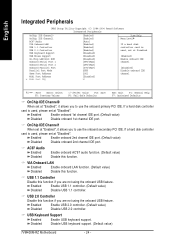
... this function. Enabled Enable onboard 1st channel IDE port. (Default value) Disabled Disable onboard 1st channel IDE port. Disabled Disable USB keyboard support. (Default value) 7VM400M-RZ Motherboard - 24 - VIA Onboard LAN Enabled Enable onboard LAN function. (Default value) Disabled Disable this function. Enabled Enable USB 1.1 controller. (Default value) Disabled Disable USB 1.1 controller...
... this function. Enabled Enable onboard 1st channel IDE port. (Default value) Disabled Disable onboard 1st channel IDE port. Disabled Disable USB keyboard support. (Default value) 7VM400M-RZ Motherboard - 24 - VIA Onboard LAN Enabled Enable onboard LAN function. (Default value) Disabled Disable this function. Enabled Enable USB 1.1 controller. (Default value) Disabled Disable USB 1.1 controller...
User Manual
Page 26
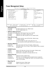
... a "POWER Key" button, you use dual color LED, power LED will available when "ACPI Suspend Type" set the keyboard power on system by mouse event. 7VM400M-RZ Motherboard - 26 - AC BACK Function Soft-Off Always in Off state when AC back to another color. Keyboard Power On Disabled Disable this function. (Default value...
... a "POWER Key" button, you use dual color LED, power LED will available when "ACPI Suspend Type" set the keyboard power on system by mouse event. 7VM400M-RZ Motherboard - 26 - AC BACK Function Soft-Off Always in Off state when AC back to another color. Keyboard Power On Disabled Disable this function. (Default value...
User Manual
Page 28
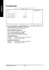
... Speed (RPM) Detect CPU/system Fan speed status automatically. SYSTEM FAN Fail Warning Disabled Fan warning function disable. (Default value) Enabled Fan warning function enable. 7VM400M-RZ Motherboard - 28 - CPU FAN Fail Warning Disabled Fan warning function disable. (Default value) Enabled Fan warning function enable.
... Speed (RPM) Detect CPU/system Fan speed status automatically. SYSTEM FAN Fail Warning Disabled Fan warning function disable. (Default value) Enabled Fan warning function enable. 7VM400M-RZ Motherboard - 28 - CPU FAN Fail Warning Disabled Fan warning function disable. (Default value) Enabled Fan warning function enable.
User Manual
Page 30
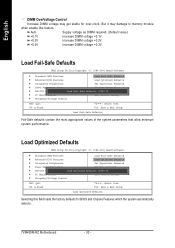
... F10: Save & Exit Setup Load Optimized Defaults Selecting this feature. But it may get stable for BIOS and Chipset Features which the system automatically detects. 7VM400M-RZ Motherboard - 30 - English DIMM OverVoltage Control Increase DIMM voltage may damage to memory module when enable this field loads the factory defaults for over-clock.
... F10: Save & Exit Setup Load Optimized Defaults Selecting this feature. But it may get stable for BIOS and Chipset Features which the system automatically detects. 7VM400M-RZ Motherboard - 30 - English DIMM OverVoltage Control Increase DIMM voltage may damage to memory module when enable this field loads the factory defaults for over-clock.

User Manual
Page 32
... Without Saving ` Frequency/Voltage Control ESC: Quit KLJI: Select Item F8: Q-Flash F10: Save & Exit Setup Abandon all Data Type "Y" will return to Setup Utility. 7VM400M-RZ Motherboard - 32 - Type "N" will quit the Setup Utility without saving to RTC CMOS. English Save & Exit Setup CMOS Setup Utility-Copyright (C) 1984-2004 Award Software ` Standard...
... Without Saving ` Frequency/Voltage Control ESC: Quit KLJI: Select Item F8: Q-Flash F10: Save & Exit Setup Abandon all Data Type "Y" will return to Setup Utility. 7VM400M-RZ Motherboard - 32 - Type "N" will quit the Setup Utility without saving to RTC CMOS. English Save & Exit Setup CMOS Setup Utility-Copyright (C) 1984-2004 Award Software ` Standard...
User Manual
Page 33
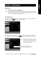
... need to install other drivers. If not, please double click the CD-ROM device icon in the list. - 33 - We recommend that came with your motherboard into your system automatically.
... need to install other drivers. If not, please double click the CD-ROM device icon in the list. - 33 - We recommend that came with your motherboard into your system automatically.


