
User Manual
Page 2
Motherboard G1.Sniper 5 Apr. 12, 2013 Motherboard G1.Sniper 5 Apr. 12, 2013
Motherboard G1.Sniper 5 Apr. 12, 2013 Motherboard G1.Sniper 5 Apr. 12, 2013

User Manual
Page 3
... order to their respective owners. All rights reserved. For product-related information, check on our website at: http://www.gigabyte.com Identifying Your Motherboard Revision The revision number on your motherboard revision before updating motherboard BIOS, drivers, or when looking for technical information. The trademarks mentioned in this manual are legally registered to assist...
... order to their respective owners. All rights reserved. For product-related information, check on our website at: http://www.gigabyte.com Identifying Your Motherboard Revision The revision number on your motherboard revision before updating motherboard BIOS, drivers, or when looking for technical information. The trademarks mentioned in this manual are legally registered to assist...
User Manual
Page 4
Table of Contents Box Contents...6 Optional Items...6 G1.Sniper 5 Motherboard Layout 7 G1.Sniper 5 Motherboard Block Diagram 8 Chapter 1 Hardware Installation 9 1-1 Installation Precautions 9 1-2 Product Specifications 10 1-3 Installing the CPU and CPU Cooler 13 1-3-1 Installing the CPU...13 1-3-2 Installing the CPU Cooler ...
Table of Contents Box Contents...6 Optional Items...6 G1.Sniper 5 Motherboard Layout 7 G1.Sniper 5 Motherboard Block Diagram 8 Chapter 1 Hardware Installation 9 1-1 Installation Precautions 9 1-2 Product Specifications 10 1-3 Installing the CPU and CPU Cooler 13 1-3-1 Installing the CPU...13 1-3-2 Installing the CPU Cooler ...

User Manual
Page 6
.... 12CT2-HDMI01-1*R) - 6 - The box contents are for reference only and the actual items shall depend on the product package you obtain. Box Contents 55 G1.Sniper 5 motherboard 55 Motherboard driver disk 55 User's Manual 55 Quick Installation Guide 55 Six SATA cables 55 I/O Shield 55 One 2-Way CrossFire bridge connector 55 One 2-Way SLI...
.... 12CT2-HDMI01-1*R) - 6 - The box contents are for reference only and the actual items shall depend on the product package you obtain. Box Contents 55 G1.Sniper 5 motherboard 55 Motherboard driver disk 55 User's Manual 55 Quick Installation Guide 55 Six SATA cables 55 I/O Shield 55 One 2-Way CrossFire bridge connector 55 One 2-Way SLI...
User Manual
Page 7
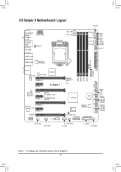
G1.Sniper 5 Motherboard Layout KB_MS_USB COAXIAL ATX_12V_2X4 R_USB30 HDMI DP_HDMI HP_PWR CPU_OPT CPU_FAN LGA1150 RST_SW PW_SW CMOS_SW SYS_FAN7 SYS_FAN6 VRIN VIOD VSA VAXG VIOA VRING VDIMM VCORE Debug LED (Note) USB30_LAN2 BIOS_SW USB30_LAN1 Renesas® uPD720210 AUDIO Intel® GbE LAN SYS_FAN1 PCIEX16_1 PEX8747 PCIEX1_1 G1.Sniper 5 Qualcomm® Atheros Killer E2201 LAN PCIEX8_1 PCIEX1_2 B_BIOS...
G1.Sniper 5 Motherboard Layout KB_MS_USB COAXIAL ATX_12V_2X4 R_USB30 HDMI DP_HDMI HP_PWR CPU_OPT CPU_FAN LGA1150 RST_SW PW_SW CMOS_SW SYS_FAN7 SYS_FAN6 VRIN VIOD VSA VAXG VIOA VRING VDIMM VCORE Debug LED (Note) USB30_LAN2 BIOS_SW USB30_LAN1 Renesas® uPD720210 AUDIO Intel® GbE LAN SYS_FAN1 PCIEX16_1 PEX8747 PCIEX1_1 G1.Sniper 5 Qualcomm® Atheros Killer E2201 LAN PCIEX8_1 PCIEX1_2 B_BIOS...

User Manual
Page 8
G1.Sniper 5 Motherboard Block Diagram 2 PCI Express x8 2 PCI Express x8 CPU CLK+/- (100 MHz) DDR3 1600/1333 MHz Dual Channel Memory LGA1150 CPU 1 PCI Express x16 1 PCI ...
G1.Sniper 5 Motherboard Block Diagram 2 PCI Express x8 2 PCI Express x8 CPU CLK+/- (100 MHz) DDR3 1600/1333 MHz Dual Channel Memory LGA1150 CPU 1 PCI Express x16 1 PCI ...

User Manual
Page 9
..., please verify that all cables and power connectors of your hardware components are connected. •• To prevent damage to the motherboard, do not allow screws to come in a high-temperature environment. •• Turning on the computer power during the installation process..., carefully read the user's manual and follow these procedures: •• Prior to installation, make sure they are required for the motherboard. •• Prior to wear an electrostatic discharge (ESD) wrist strap when handling electronic components such as a result of an antistatic...
..., please verify that all cables and power connectors of your hardware components are connected. •• To prevent damage to the motherboard, do not allow screws to come in a high-temperature environment. •• Turning on the computer power during the installation process..., carefully read the user's manual and follow these procedures: •• Prior to installation, make sure they are required for the motherboard. •• Prior to wear an electrostatic discharge (ESD) wrist strap when handling electronic components such as a result of an antistatic...
User Manual
Page 12
... Intel® Smart Response Technology Support for Windows 8/7 Form Factor ŠŠ E-ATX Form Factor; 30.5cm x 26.4cm * GIGABYTE reserves the right to make any changes to the product specifications and product-related information without prior notice. * Please visit... the software listed in APP Center may also differ depending on the cooler you install. 2 x 128 Mbit flash Use of each application may differ by motherboard model. I/O Controller ŠŠ iTE® I/O Controller Chip Hardware ŠŠ Monitor ŠŠ ŠŠ ŠŠ ŠŠ ...
... Intel® Smart Response Technology Support for Windows 8/7 Form Factor ŠŠ E-ATX Form Factor; 30.5cm x 26.4cm * GIGABYTE reserves the right to make any changes to the product specifications and product-related information without prior notice. * Please visit... the software listed in APP Center may also differ depending on the cooler you install. 2 x 128 Mbit flash Use of each application may differ by motherboard model. I/O Controller ŠŠ iTE® I/O Controller Chip Hardware ŠŠ Monitor ŠŠ ŠŠ ŠŠ ŠŠ ...

User Manual
Page 13
... card, memory, hard drive, etc. 1-3-1 Installing the CPU A. Locate the alignment keys on the motherboard CPU socket and the notches on the computer if the CPU cooler is not recommended that the motherboard supports the CPU. (Go to GIGABYTE's website for the peripherals. 1-3 Installing the CPU and CPU Cooler Read the following guidelines...
... card, memory, hard drive, etc. 1-3-1 Installing the CPU A. Locate the alignment keys on the motherboard CPU socket and the notches on the computer if the CPU cooler is not recommended that the motherboard supports the CPU. (Go to GIGABYTE's website for the peripherals. 1-3 Installing the CPU and CPU Cooler Read the following guidelines...

User Manual
Page 14
... may pop off the computer and unplug the power cord from the socket with the socket alignment keys) and gently insert the CPU into the motherboard CPU socket. •• Before installing the CPU, make sure the front end of the CPU. The protective plastic cover may align the CPU notches...
... may pop off the computer and unplug the power cord from the socket with the socket alignment keys) and gently insert the CPU into the motherboard CPU socket. •• Before installing the CPU, make sure the front end of the CPU. The protective plastic cover may align the CPU notches...

User Manual
Page 15
... above shows, the installation is to install.) Step 3: Place the cooler atop the CPU, aligning the four push pins through the pin holes on the motherboard. Step 4: You should hear a "click" when pushing down on the surface of the installed CPU. Step 6: Finally, attach the power connector of the ...of the arrow sign on the male push pin. (Turning the push pin along the direction of arrow is to remove the cooler, on the motherboard. •• For the waterblocks at each push pin. 1-3-2 Installing the CPU Cooler Follow the steps below to correctly install the CPU cooler on...
... above shows, the installation is to install.) Step 3: Place the cooler atop the CPU, aligning the four push pins through the pin holes on the motherboard. Step 4: You should hear a "click" when pushing down on the surface of the installed CPU. Step 6: Finally, attach the power connector of the ...of the arrow sign on the male push pin. (Turning the push pin along the direction of arrow is to remove the cooler, on the motherboard. •• For the waterblocks at each push pin. 1-3-2 Installing the CPU Cooler Follow the steps below to correctly install the CPU cooler on...
User Manual
Page 16
... mode with two memory modules, we recommend that memory of the same capacity, brand, speed, and chips be used . (Go to GIGABYTE's website for the latest supported memory speeds and memory modules.) •• Always turn off the computer and unplug the power cord from...of the memory. The four DDR3 memory sockets are unable to insert the memory, switch the direction. 1-4-1 Dual Channel Memory Configuration This motherboard provides four DDR3 memory sockets and supports Dual Channel Technology. Hardware Installation - 16 - A memory module can be enabled if only one ...
... mode with two memory modules, we recommend that memory of the same capacity, brand, speed, and chips be used . (Go to GIGABYTE's website for the latest supported memory speeds and memory modules.) •• Always turn off the computer and unplug the power cord from...of the memory. The four DDR3 memory sockets are unable to insert the memory, switch the direction. 1-4-1 Dual Channel Memory Configuration This motherboard provides four DDR3 memory sockets and supports Dual Channel Technology. Hardware Installation - 16 - A memory module can be enabled if only one ...

User Manual
Page 17
As indicated in the picture on the left, place your memory modules in one direction. Place the memory module on this motherboard. 1-4-2 Installing a Memory Before installing a memory module, make sure to turn off the computer and unplug the power cord from the power outlet to prevent damage ...
As indicated in the picture on the left, place your memory modules in one direction. Place the memory module on this motherboard. 1-4-2 Installing a Memory Before installing a memory module, make sure to turn off the computer and unplug the power cord from the power outlet to prevent damage ...
User Manual
Page 18
... to correctly install your expansion card in the expansion slot. 1. Secure the card's metal bracket to install an expansion card: •• Make sure the motherboard supports the expansion card. Remove the metal slot cover from the power outlet before you begin to the chassis back panel with a screw. 5. After installing...
... to correctly install your expansion card in the expansion slot. 1. Secure the card's metal bracket to install an expansion card: •• Make sure the motherboard supports the expansion card. Remove the metal slot cover from the power outlet before you begin to the chassis back panel with a screw. 5. After installing...

User Manual
Page 19
A CrossFire/SLI-supported motherboard with sufficient power is selected. Configuring the Graphics Card Driver C-1. System Requirements -- Step 3: Plug the display cable into the graphics card on your graphics cards. (...
A CrossFire/SLI-supported motherboard with sufficient power is selected. Configuring the Graphics Card Driver C-1. System Requirements -- Step 3: Plug the display cable into the graphics card on your graphics cards. (...

User Manual
Page 20
... default playback device. Do not rock it straight out from the connector. USB 3.0/2.0 Port The USB 3.0 port supports the USB 3.0 specification and is from the motherboard. •• When removing the cable, pull it side to side to an external audio system that your DisplayPort-supported monitor. You can use this...
... default playback device. Do not rock it straight out from the connector. USB 3.0/2.0 Port The USB 3.0 port supports the USB 3.0 specification and is from the motherboard. •• When removing the cable, pull it side to side to an external audio system that your DisplayPort-supported monitor. You can use this...

User Manual
Page 21
... audio out to the instructions on the previous page for the configuration dialog box.) Triple Display Configurations for sound playback is recommended that you install motherboard drivers in connector. Headphone/Speaker Out Jack This audio output jack supports audio amplifying function. Refer to an external audio system that your headphone/speaker...
... audio out to the instructions on the previous page for the configuration dialog box.) Triple Display Configurations for sound playback is recommended that you install motherboard drivers in connector. Headphone/Speaker Out Jack This audio output jack supports audio amplifying function. Refer to an external audio system that your headphone/speaker...
User Manual
Page 22
...environment when 11 22 33 they want to factory defaults when needed. F_AUDIO(H) F_PANEL(NH) Hardware Installation - 22 - Voltage measurement points(G1.Sniper 3) Voltage measurement points(G1.Sniper 3) DDIIPP 11 22 33 44 DDIIPP 11 22 33 44 DIP 1 234 DIP 1 234 MBIOS_LED BBIOS_LED PCIe Control (Z87X-UP7) ... is active) DDIIPP 11 22 33 PCIe power connector (SATA)(X58A-OC) DDIIPP 11 22 33 DDIIPP 11 22 33 Quick Buttons This motherboard has 3 quick buttons: power button, reset button and clear CMOS button. Voltage measurement module(X58A-OC) PCIe power connector (SATA)(X58A-...
...environment when 11 22 33 they want to factory defaults when needed. F_AUDIO(H) F_PANEL(NH) Hardware Installation - 22 - Voltage measurement points(G1.Sniper 3) Voltage measurement points(G1.Sniper 3) DDIIPP 11 22 33 44 DDIIPP 11 22 33 44 DIP 1 234 DIP 1 234 MBIOS_LED BBIOS_LED PCIe Control (Z87X-UP7) ... is active) DDIIPP 11 22 33 PCIe power connector (SATA)(X58A-OC) DDIIPP 11 22 33 DDIIPP 11 22 33 Quick Buttons This motherboard has 3 quick buttons: power button, reset button and clear CMOS button. Voltage measurement module(X58A-OC) PCIe power connector (SATA)(X58A-...

User Manual
Page 24
... and your devices are compliant with the connectors you wish to connect. •• Before installing the devices, be sure to the connector on the motherboard. Hardware Installation - 24 -
... and your devices are compliant with the connectors you wish to connect. •• Before installing the devices, be sure to the connector on the motherboard. Hardware Installation - 24 -

User Manual
Page 25
... will not start. Connect the power supply cable to the CPU. If the 12V power connector is turned off and all the components on the motherboard. Hardware Installation Definition 1 GND (Only for 2x4-pin 12V) 2 GND (Only for 2x4-pin 12V) 3 GND 4 GND 5 +12V (Only for 2x4-pin 12V) 6 +12V (Only...
... will not start. Connect the power supply cable to the CPU. If the 12V power connector is turned off and all the components on the motherboard. Hardware Installation Definition 1 GND (Only for 2x4-pin 12V) 2 GND (Only for 2x4-pin 12V) 3 GND 4 GND 5 +12V (Only for 2x4-pin 12V) 6 +12V (Only...


