User Manual
Page 1
GA-3PXSL-RH AMD Socket AM2 Motherboard USER'S MANUAL AMD®AM2 Processor Motherboard Rev. 1003 * The WEEE marking on the product indicates this product must not be disposed of with user's other household waste and must be handed over to a designated collection point for the recycling of waste electrical and electronic equipment!! * The WEEE marking applies only in European Union's member states.
GA-3PXSL-RH AMD Socket AM2 Motherboard USER'S MANUAL AMD®AM2 Processor Motherboard Rev. 1003 * The WEEE marking on the product indicates this product must not be disposed of with user's other household waste and must be handed over to a designated collection point for the recycling of waste electrical and electronic equipment!! * The WEEE marking applies only in European Union's member states.
User Manual
Page 2
English GA-3PXSL-RH Motherboard Table of Content Item Checklist 4 WARNING 4 Chapter 1 Introduction 5 1.1.Features Summary 5 1.2GA-3PXSL-RH Motherboard Components 7 Chapter 2Hardware Installation Process 9 2-1: Installing Processor and CPU Haet Sink 9 2-1-1: Installing CPU ...9 2-1-2: Installing CPU Cooler Fan 10 2-2: Install memory modules 11 2-3: Install expansion ...
English GA-3PXSL-RH Motherboard Table of Content Item Checklist 4 WARNING 4 Chapter 1 Introduction 5 1.1.Features Summary 5 1.2GA-3PXSL-RH Motherboard Components 7 Chapter 2Hardware Installation Process 9 2-1: Installing Processor and CPU Haet Sink 9 2-1-1: Installing CPU ...9 2-1-2: Installing CPU Cooler Fan 10 2-2: Install memory modules 11 2-3: Install expansion ...
User Manual
Page 4
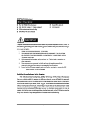
... base without worrying about short circuits. Sometimes you can still attach the motherboard to the mounting holes. English GA-3PXSL-RH Motherboard Item Checklist The GA-3PXSL-RH motherboard IDE (ATA100 ) cable x 1 / Floppy cable x 1 CD for motherboard driver & utility GA-3PXSL-RH user's manual Serial ATA cable x 4 I/O Shield Kit WARNING! Computer motherboards and expansion cards contain very delicate Integrated...
... base without worrying about short circuits. Sometimes you can still attach the motherboard to the mounting holes. English GA-3PXSL-RH Motherboard Item Checklist The GA-3PXSL-RH motherboard IDE (ATA100 ) cable x 1 / Floppy cable x 1 CD for motherboard driver & utility GA-3PXSL-RH user's manual Serial ATA cable x 4 I/O Shield Kit WARNING! Computer motherboards and expansion cards contain very delicate Integrated...
User Manual
Page 6
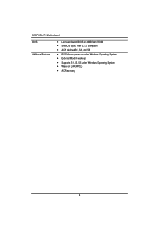
Rev 2.3.3. English GA-3PXSL-RH Motherboard BIOS Additional Features Licensed Award BIOS on LAN (WOL) AC Recovery 6 compliant ACPI defined S1, S3, and S5 PS/2 Mouse power on under Windows Operating System External Modem wake up Supports S1, S3, S5 under Windows Operating System Wake on 4MB flash ROM SMBIOS Spec.
Rev 2.3.3. English GA-3PXSL-RH Motherboard BIOS Additional Features Licensed Award BIOS on LAN (WOL) AC Recovery 6 compliant ACPI defined S1, S3, and S5 PS/2 Mouse power on under Windows Operating System External Modem wake up Supports S1, S3, S5 under Windows Operating System Wake on 4MB flash ROM SMBIOS Spec.
User Manual
Page 8
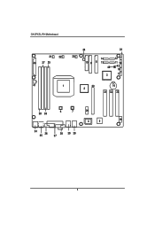
English GA-3PXSL-RH Motherboard 21 22 40 27 25 24 23 20 14 12 10 9 8 13 11 15 42 43 18 3 17 41 1 30 16 2 31 32 33 28 26 6 7 29 4 5 19 34 36 35 38 39 39 37 8
English GA-3PXSL-RH Motherboard 21 22 40 27 25 24 23 20 14 12 10 9 8 13 11 15 42 43 18 3 17 41 1 30 16 2 31 32 33 28 26 6 7 29 4 5 19 34 36 35 38 39 39 37 8
User Manual
Page 10
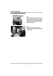
Fig.2 Please connect the CPU cooler fan power connector to the cooler manual for detailed installation instructions). English GA-3PXSL-RH Motherboard 2-1-2: Installing CPU Cooler Fan Fig.1 Before installing the CPU cooler fan, please first add an even layer of the CPU. Install all the CPU cooler components (Please refer to the CPU_FAN connector located on the surface of heat paste on the motherboard. 10
Fig.2 Please connect the CPU cooler fan power connector to the cooler manual for detailed installation instructions). English GA-3PXSL-RH Motherboard 2-1-2: Installing CPU Cooler Fan Fig.1 Before installing the CPU cooler fan, please first add an even layer of the CPU. Install all the CPU cooler components (Please refer to the CPU_FAN connector located on the surface of heat paste on the motherboard. 10

User Manual
Page 11
Wrong orientation will automatically detects memory type and size. Memory size can only fit in one direction due to the notch. 2-2: Install memory modules Hardware Installation Process GA-3PXSL-RH has 4 dual inline memory module (DIMM) socets. It supports the Dual Channel Technology. Please change the insert orientation. The BIOS will cause improper installation. To install the memory module, just push it vertically into the DIMM socket .The DIMM module can vary between sockets. CHANNEL B CHANNEL A 11
Wrong orientation will automatically detects memory type and size. Memory size can only fit in one direction due to the notch. 2-2: Install memory modules Hardware Installation Process GA-3PXSL-RH has 4 dual inline memory module (DIMM) socets. It supports the Dual Channel Technology. Please change the insert orientation. The BIOS will cause improper installation. To install the memory module, just push it vertically into the DIMM socket .The DIMM module can vary between sockets. CHANNEL B CHANNEL A 11
User Manual
Page 12
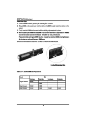
... DIMM Slot Populations Mode Single Channel DIMMA1 Install Dual Channel Dual Channel Install Install Slot DIMMB1 DIMMA2 Install Install Install Install DIMMB2 Install 12 English GA-3PXSL-RH Motherboard Installation Step: 1. Unlock a DIMM socket by pressing the retaining clips outwards. 2.
... DIMM Slot Populations Mode Single Channel DIMMA1 Install Dual Channel Dual Channel Install Install Slot DIMMB1 DIMMA2 Install Install Install Install DIMMB2 Install 12 English GA-3PXSL-RH Motherboard Installation Step: 1. Unlock a DIMM socket by pressing the retaining clips outwards. 2.
User Manual
Page 14
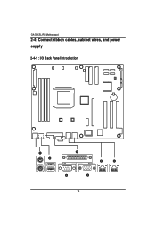
English GA-3PXSL-RH Motherboard 2-4: Connect ribbon cables, cabinet wires, and power supply 2-4-1 : I/O Back Panel Introduction 14
English GA-3PXSL-RH Motherboard 2-4: Connect ribbon cables, cabinet wires, and power supply 2-4-1 : I/O Back Panel Introduction 14
User Manual
Page 16
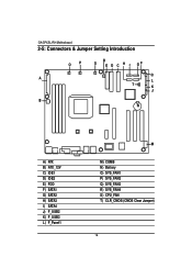
English GA-3PXSL-RH Motherboard 2-5: Connectors & Jumper Setting Introduction OP R S E D C H I GF Q A L T K J B N A) ATX B) ATX _12V C) IDE1 D) IDE2 E) FDD F) SATA1 G) SATA2 H) SATA3 I) SATA4 J) F_USB2 K) F_USB3 L) F_Panel1 M M) COMB N) Battery O) SYS_FAN1 P) SYS_FAN2 Q) SYS_FAN3 R) SYS_FAN4 S) CPU_FAN T) CLR_CMOS (CMOS Clear Jumper) 16
English GA-3PXSL-RH Motherboard 2-5: Connectors & Jumper Setting Introduction OP R S E D C H I GF Q A L T K J B N A) ATX B) ATX _12V C) IDE1 D) IDE2 E) FDD F) SATA1 G) SATA2 H) SATA3 I) SATA4 J) F_USB2 K) F_USB3 L) F_Panel1 M M) COMB N) Battery O) SYS_FAN1 P) SYS_FAN2 Q) SYS_FAN3 R) SYS_FAN4 S) CPU_FAN T) CLR_CMOS (CMOS Clear Jumper) 16
User Manual
Page 18
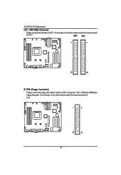
The red stripe of the ribbon cable must be the same side with the Pin1. 1 2 33 34 18 The red stripe of the ribbon cable must be the same side with the Pin1. IDE2 IDE1 2 1 40 39 E) FDD (Floppy Connector) Please connect the floppy drive ribbon cables to IDE1. It supports 1.2M,1.44M and 2.88Mbytes floppy disk types. English GA-3PXSL-RH Motherboard C/D ) IDE1/IDE2 Connector Please connect first harddisk to FDD.
The red stripe of the ribbon cable must be the same side with the Pin1. 1 2 33 34 18 The red stripe of the ribbon cable must be the same side with the Pin1. IDE2 IDE1 2 1 40 39 E) FDD (Floppy Connector) Please connect the floppy drive ribbon cables to IDE1. It supports 1.2M,1.44M and 2.88Mbytes floppy disk types. English GA-3PXSL-RH Motherboard C/D ) IDE1/IDE2 Connector Please connect first harddisk to FDD.

User Manual
Page 20
... Front Panel Power On/Off Button No Connect KEY KEY KEY KEY KEY KEY KEY KEY KEY Speaker connector Speaker connector 20 RES+ HD- English GA-3PXSL-RH Motherboard L ) F_Panel1 (2x10 Pins Front Panel Connectors) Please connect the power LED, PC speaker, reset switch and power switch etc of your chassis front panel...
... Front Panel Power On/Off Button No Connect KEY KEY KEY KEY KEY KEY KEY KEY KEY Speaker connector Speaker connector 20 RES+ HD- English GA-3PXSL-RH Motherboard L ) F_Panel1 (2x10 Pins Front Panel Connectors) Please connect the power LED, PC speaker, reset switch and power switch etc of your chassis front panel...
User Manual
Page 22
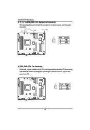
current up to prevent the CPU from running under abnormal condition or damaged by overheating.The CPU fan connector supports Max. Definition 1 GND 2 +12V 3 Sense 22 SYS_FAN2 SYS_FAN1 SYS_FAN4 SYS_FAN3 1 Pin No. Definition 1 GND 2 +12V 3 Sense S ) CPU_FAN (CPU Fan Connector) Please note, a proper installation of the CPU cooler is essential to 1A . 1 Pin No. English GA-3PXSL-RH Motherboard O / P / Q / R ) SYS_FAN1/2/3/4 (System Fan Connectors) This connector allows you to link with the cooling fan on the system case to lower the system temperature.
current up to prevent the CPU from running under abnormal condition or damaged by overheating.The CPU fan connector supports Max. Definition 1 GND 2 +12V 3 Sense 22 SYS_FAN2 SYS_FAN1 SYS_FAN4 SYS_FAN3 1 Pin No. Definition 1 GND 2 +12V 3 Sense S ) CPU_FAN (CPU Fan Connector) Please note, a proper installation of the CPU cooler is essential to 1A . 1 Pin No. English GA-3PXSL-RH Motherboard O / P / Q / R ) SYS_FAN1/2/3/4 (System Fan Connectors) This connector allows you to link with the cooling fan on the system case to lower the system temperature.
User Manual
Page 26
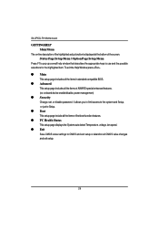
... Window press . z Advanced This setup page includes all the items in standard compatible BIOS. z Main This setup page includes all the items of the screen. GA-3PXSL-RH Motherboard GETTINGHELP Main Menu The on-line description of the highlighted setup function is displayed at the bottom of AWARD special enhanced features. (ex: onboard...
... Window press . z Advanced This setup page includes all the items in standard compatible BIOS. z Main This setup page includes all the items of the screen. GA-3PXSL-RH Motherboard GETTINGHELP Main Menu The on-line description of the highlighted setup function is displayed at the bottom of AWARD special enhanced features. (ex: onboard...

User Manual
Page 28
GA-3PXSL-RH Motherboard Phoenix-Award WorkstationBIOS CMOS Setup Utility Main Advanced Security Boot PC Health Exit System Information Item Help System Information Product Name: GA-XXXXXX BIOS Version: F1 Build Date: xx-xx-xx Manufactory: Chipset Type: LAN1 MAC Address: LAN2 MAC Address: CPU Core Frequency CPU Frequency Ratio CPU ...
GA-3PXSL-RH Motherboard Phoenix-Award WorkstationBIOS CMOS Setup Utility Main Advanced Security Boot PC Health Exit System Information Item Help System Information Product Name: GA-XXXXXX BIOS Version: F1 Build Date: xx-xx-xx Manufactory: Chipset Type: LAN1 MAC Address: LAN2 MAC Address: CPU Core Frequency CPU Frequency Ratio CPU ...
User Manual
Page 30
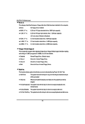
..., But Keyboard The system boot will not stop for all errors except a keyboard error. (Default value) All, But Diskette The system boot will be prompted. GA-3PXSL-RH Motherboard Drive A The category identifies the types of 1.2MB (as opposed 1.44MB) on a 3.5-inch diskette. Floppy 3 Mode Support This is required to halt when an...
..., But Keyboard The system boot will not stop for all errors except a keyboard error. (Default value) All, But Diskette The system boot will be prompted. GA-3PXSL-RH Motherboard Drive A The category identifies the types of 1.2MB (as opposed 1.44MB) on a 3.5-inch diskette. Floppy 3 Mode Support This is required to halt when an...
User Manual
Page 32
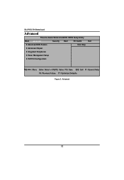
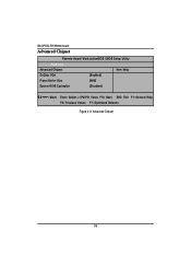
GA-3PXSL-RH Motherboard Advanced Phoenix-Award WorkstationBIOS CMOS Setup Utility Main Advanced Security Boot PC Health Exit Advanced BIOS Feature Item Help Advanced Chipset Integrated Peripherals Power Management Setup PnP/PCI Configuration K L J I : Move Enter: Select +/-/PU/PD: Value F10: Save ESC: Exit F1: General Help F5: Previous Values F7: Optimized Defaults Figure 2: Advanced 32
GA-3PXSL-RH Motherboard Advanced Phoenix-Award WorkstationBIOS CMOS Setup Utility Main Advanced Security Boot PC Health Exit Advanced BIOS Feature Item Help Advanced Chipset Integrated Peripherals Power Management Setup PnP/PCI Configuration K L J I : Move Enter: Select +/-/PU/PD: Value F10: Save ESC: Exit F1: General Help F5: Previous Values F7: Optimized Defaults Figure 2: Advanced 32
User Manual
Page 34
DMI Event Log Enabled Disabled Store POST error message to select power-on status for NumLock. GA-3PXSL-RH Motherboard Boot Up Floppy Seek During POST, BIOS will determine the floppy disk drive installed is 40 or 80 tracks. 360K type is 360K. Boot ...
DMI Event Log Enabled Disabled Store POST error message to select power-on status for NumLock. GA-3PXSL-RH Motherboard Boot Up Floppy Seek During POST, BIOS will determine the floppy disk drive installed is 40 or 80 tracks. 360K type is 360K. Boot ...
User Manual
Page 36
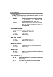
GA-3PXSL-RH Motherboard Advanced Chipset Phoenix-Award WorkstationBIOS CMOS Setup Utility Advanced Advanced Chipset Item Help OnChip VGA [Enabled] Frame Buffer Size [64M] System BIOS Cacheable [Disabled] K L J I : Move Enter: Select +/-/PU/PD: Value F10: Save ESC: Exit F1: General Help F5: Previous Values F7: Optimized Defaults Figure 2-2: Advanced Chipset 36
GA-3PXSL-RH Motherboard Advanced Chipset Phoenix-Award WorkstationBIOS CMOS Setup Utility Advanced Advanced Chipset Item Help OnChip VGA [Enabled] Frame Buffer Size [64M] System BIOS Cacheable [Disabled] K L J I : Move Enter: Select +/-/PU/PD: Value F10: Save ESC: Exit F1: General Help F5: Previous Values F7: Optimized Defaults Figure 2-2: Advanced Chipset 36
User Manual
Page 38
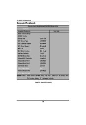
GA-3PXSL-RH Motherboard Integrated Peripherals Phoenix-Award WorkstationBIOS CMOS Setup Utility Advanced Integrated Peripherals Item Help IDE Function Setup RAID Config OnChip USB [V1.1+V2.0] USB Memory ...
GA-3PXSL-RH Motherboard Integrated Peripherals Phoenix-Award WorkstationBIOS CMOS Setup Utility Advanced Integrated Peripherals Item Help IDE Function Setup RAID Config OnChip USB [V1.1+V2.0] USB Memory ...


