
Manual
Page 1
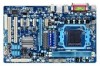
GA-770T-D3L AM3+ socket motherboard for AMD Phenom™ II processor/ AMD Athlon™ II processor User's Manual Rev. 3101 12ME-770TD3L-3101R
GA-770T-D3L AM3+ socket motherboard for AMD Phenom™ II processor/ AMD Athlon™ II processor User's Manual Rev. 3101 12ME-770TD3L-3101R

Manual
Page 3
... reserved. Changes to the specifications and features in any form or by GIGABYTE without GIGABYTE's prior written permission. Documentation Classifications In order to their respective owners. Check your motherboard looks like this manual may be made by any means without prior notice. For example, "... the product. For detailed product information, carefully read the User's Manual. The trademarks mentioned in this manual are legally registered to assist in the use of this product, GIGABYTE provides the following types of documentations: For quick set-up of ...
... reserved. Changes to the specifications and features in any form or by GIGABYTE without GIGABYTE's prior written permission. Documentation Classifications In order to their respective owners. Check your motherboard looks like this manual may be made by any means without prior notice. For example, "... the product. For detailed product information, carefully read the User's Manual. The trademarks mentioned in this manual are legally registered to assist in the use of this product, GIGABYTE provides the following types of documentations: For quick set-up of ...
Manual
Page 5
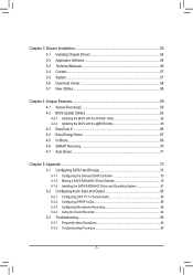
Chapter 3 Drivers Installation 55 3-1 Installing Chipset Drivers 55 3-2 Application Software 56 3-3 Technical Manuals 56 3-4 Contact...57 3-5 System...57 3-6 Download Center 58 3-7 New Utilities...58 Chapter 4 Unique Features 59 4-1 Xpress Recovery2 59 4-2 BIOS Update Utilities 62 4-2-1 Updating the BIOS ...
Chapter 3 Drivers Installation 55 3-1 Installing Chipset Drivers 55 3-2 Application Software 56 3-3 Technical Manuals 56 3-4 Contact...57 3-5 System...57 3-6 Download Center 58 3-7 New Utilities...58 Chapter 4 Unique Features 59 4-1 Xpress Recovery2 59 4-2 BIOS Update Utilities 62 4-2-1 Updating the BIOS ...
Manual
Page 6
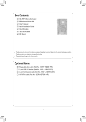
The box contents are for reference only. Optional Items Floppy disk drive cable (Part No. 12CF1-1FD001-7*R) 2-port USB 2.0 bracket (Part No. 12CR1-1UB030-5*R) 2-port SATA power cable (Part No. 12CF1-2SERPW-0*R) S/PDIF In cable (Part No. 12CR1-1SPDIN-0*R) - 6 - Box Contents GA-770T-D3L motherboard Motherboard driver disk User's Manual Quick Installation Guide One IDE cable Two SATA cables I/O Shield • The box contents above are subject to change without notice. • The motherboard image is for reference only and the actual items shall depend on the product package you obtain.
The box contents are for reference only. Optional Items Floppy disk drive cable (Part No. 12CF1-1FD001-7*R) 2-port USB 2.0 bracket (Part No. 12CR1-1UB030-5*R) 2-port SATA power cable (Part No. 12CF1-2SERPW-0*R) S/PDIF In cable (Part No. 12CR1-1SPDIN-0*R) - 6 - Box Contents GA-770T-D3L motherboard Motherboard driver disk User's Manual Quick Installation Guide One IDE cable Two SATA cables I/O Shield • The box contents above are subject to change without notice. • The motherboard image is for reference only and the actual items shall depend on the product package you obtain.

Manual
Page 9
...; To prevent damage to the motherboard, do not have an ESD wrist strap, keep your dealer. Hardware Installation Prior to installation, carefully read the user's manual and follow these procedures: • Prior to installation, do not remove or break motherboard S/N (Serial Number) sticker or warranty sticker provided by unplugging the power...
...; To prevent damage to the motherboard, do not have an ESD wrist strap, keep your dealer. Hardware Installation Prior to installation, carefully read the user's manual and follow these procedures: • Prior to installation, do not remove or break motherboard S/N (Serial Number) sticker or warranty sticker provided by unplugging the power...
Manual
Page 15
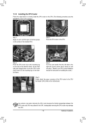
... the steps below to correctly install the CPU cooler on the CPU. (The following procedure uses the GIGABYTE cooler as the picture above shows) to lock into place. (Refer to your CPU cooler installation manual for instructions on installing the cooler.) Step 5: Finally, attach the power connector of the CPU cooler to...
... the steps below to correctly install the CPU cooler on the CPU. (The following procedure uses the GIGABYTE cooler as the picture above shows) to lock into place. (Refer to your CPU cooler installation manual for instructions on installing the cooler.) Step 5: Finally, attach the power connector of the CPU cooler to...

Manual
Page 18
... Card: Gently push back on the lever on the top edge of the card until it is securely seated in the slot. 3. Carefully read the manual that supports your computer. Align the card with your expansion card. • Always turn off the computer and unplug the power cord from the power...
... Card: Gently push back on the lever on the top edge of the card until it is securely seated in the slot. 3. Carefully read the manual that supports your computer. Align the card with your expansion card. • Always turn off the computer and unplug the power cord from the power...
Manual
Page 27
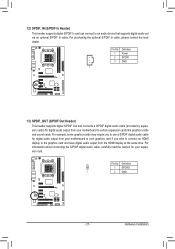
... graphics card and have digital audio output from your expansion card. Hardware Installation For information about connecting the S/PDIF digital audio cable, carefully read the manual for your motherboard to an audio device that supports digital audio out via an optional S/PDIF In cable. 12) SPDIF_IN (S/PDIF In Header) This header...
... graphics card and have digital audio output from your expansion card. Hardware Installation For information about connecting the S/PDIF digital audio cable, carefully read the manual for your motherboard to an audio device that supports digital audio out via an optional S/PDIF In cable. 12) SPDIF_IN (S/PDIF In Header) This header...

Manual
Page 29
... do so may cause damage to the motherboard. • After system restart, go to BIOS Setup to load factory defaults (select Load Optimized Defaults) or manually configure the BIOS settings (refer to Chapter 2, "BIOS Setup," for a few seconds. Hardware Installation date information and BIOS configurations) and reset the CMOS values to...
... do so may cause damage to the motherboard. • After system restart, go to BIOS Setup to load factory defaults (select Load Optimized Defaults) or manually configure the BIOS settings (refer to Chapter 2, "BIOS Setup," for a few seconds. Hardware Installation date information and BIOS configurations) and reset the CMOS values to...

Manual
Page 36
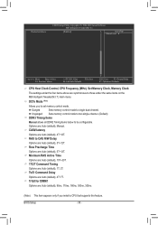
...(All Cores) This option is configurable only when Advanced Clock Calibration is dependent on the CPU being used. Options are : Auto (default), Manual. Options are : -12%~+12%. The adjustable range is set the CPU host frequency. The adjustable range is enabled. Note: If your ...is configurable only when Advanced Clock Calibration is highly recommended that the CPU frequency be set to be configurable. Manual allows the CPU Frequency (MHz) item below to manually enable/disable CPU Core 1/2/3. Normal Uses the standard AMD EC firmware version. (Default) Hybrid Uses the specific...
...(All Cores) This option is configurable only when Advanced Clock Calibration is dependent on the CPU being used. Options are : Auto (default), Manual. Options are : -12%~+12%. The adjustable range is set the CPU host frequency. The adjustable range is enabled. Note: If your ...is configurable only when Advanced Clock Calibration is highly recommended that the CPU frequency be set to be configurable. Manual allows the CPU Frequency (MHz) item below to manually enable/disable CPU Core 1/2/3. Normal Uses the standard AMD EC firmware version. (Default) Hybrid Uses the specific...

Manual
Page 37
... the HT Link between the CPU and chipset. PCIE Clock(MHz) Allows you to X5.33. X5.33 Sets Memory Clock to manually set the memory clock. Manual allows the memory clock control item below to be configurable. (Default: Auto) Memory Clock This option is configurable only when Set Memory... Clock is from 100 MHz to 200 MHz~2 GHz. X4.00 Sets Memory Clock to Manual. The adjustable range is set the memory clock as required. BIOS Setup Auto BIOS will automatically adjust the HT Link Frequency. (Default) 200 MHz...
... the HT Link between the CPU and chipset. PCIE Clock(MHz) Allows you to X5.33. X5.33 Sets Memory Clock to manually set the memory clock. Manual allows the memory clock control item below to be configurable. (Default: Auto) Memory Clock This option is configurable only when Set Memory... Clock is from 100 MHz to 200 MHz~2 GHz. X4.00 Sets Memory Clock to Manual. The adjustable range is set the memory clock as required. BIOS Setup Auto BIOS will automatically adjust the HT Link Frequency. (Default) 200 MHz...
Manual
Page 38
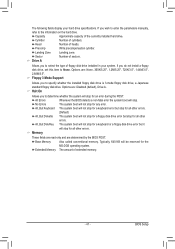
...: Auto (default), 1T, 2T. BIOS Setup - 38 - Unganged Sets memory control mode to two single-channel. (Default) DDR3 Timing Items Manual allows all DDR2 Timing items below to single dual-channel. Trfc0 for DIMM1 Options are : Auto (default), 4T~7T. RAS to set memory ...same items on the MB Intelligent Tweaker(M.I.T.) main menu. Options are : Auto (default), 4T~12T. CAS# latency Options are : Auto (default), Manual. DCTs Mode (Note) Allows you install a CPU that supports this feature. CMOS Setup Utility-Copyright (C) 1984-2010 Award Software MB Intelligent Tweaker(M.I.T.) Channel...
...: Auto (default), 1T, 2T. BIOS Setup - 38 - Unganged Sets memory control mode to two single-channel. (Default) DDR3 Timing Items Manual allows all DDR2 Timing items below to single dual-channel. Trfc0 for DIMM1 Options are : Auto (default), 4T~7T. RAS to set memory ...same items on the MB Intelligent Tweaker(M.I.T.) main menu. Options are : Auto (default), 4T~12T. CAS# latency Options are : Auto (default), Manual. DCTs Mode (Note) Allows you install a CPU that supports this feature. CMOS Setup Utility-Copyright (C) 1984-2010 Award Software MB Intelligent Tweaker(M.I.T.) Channel...

Manual
Page 39
...banks of the CPU. Auto sets the CPU Northbridge VID voltage as required. Trfc2 for DIMM2 Options are : Auto (default), 4T~7T. Manual allows all voltage control items below to be configurable. (Default: Auto) DRAM Voltage Control Allows you to 1.800V. Normal Supplies the North .... (Default) 1.100V ~ 1.800V The adjustable range is from 1.100V to set the CPU voltage. CPU NB VID Control (Note) Allows you to manually set the system voltages as required. BIOS Setup Precharge Time Options are : Auto (default), 90ns, 110ns, 160ns, 300ns, 350ns. Row Cycle Time Options...
...banks of the CPU. Auto sets the CPU Northbridge VID voltage as required. Trfc2 for DIMM2 Options are : Auto (default), 4T~7T. Manual allows all voltage control items below to be configurable. (Default: Auto) DRAM Voltage Control Allows you to 1.800V. Normal Supplies the North .... (Default) 1.100V ~ 1.800V The adjustable range is from 1.100V to set the CPU voltage. CPU NB VID Control (Note) Allows you to manually set the system voltages as required. BIOS Setup Precharge Time Options are : Auto (default), 90ns, 110ns, 160ns, 300ns, 350ns. Row Cycle Time Options...
Manual
Page 41
... for any error. All, But Disk/Key The system boot will stop for all other errors. BIOS Setup If you wish to enter the parameters manually, refer to None. Options are : Disabled (default), Drive A. Typically, 640 KB will not stop for the MS-DOS operating system. If you do not install...
... for any error. All, But Disk/Key The system boot will stop for all other errors. BIOS Setup If you wish to enter the parameters manually, refer to None. Options are : Disabled (default), Drive A. Typically, 640 KB will not stop for the MS-DOS operating system. If you do not install...

Manual
Page 55
...later. Click Yes to install. • Please ignore the popup dialog box(es) (e.g. Or click Install Single Items to manually select the drivers you want to manually select the utilities to install. Failure to do so may affect the driver installation. • Some device drivers will appear...mark (by right-clicking your system automatically during the driver installation. After the system restart, "Xpress Install" will continue to install new GIGABYTE utilities. Or click No if you wish to automatically install the utilities. You can click the Install All button and "Xpress Install"...
...later. Click Yes to install. • Please ignore the popup dialog box(es) (e.g. Or click Install Single Items to manually select the drivers you want to manually select the utilities to install. Failure to do so may affect the driver installation. • Some device drivers will appear...mark (by right-clicking your system automatically during the driver installation. After the system restart, "Xpress Install" will continue to install new GIGABYTE utilities. Or click No if you wish to automatically install the utilities. You can click the Install All button and "Xpress Install"...
Manual
Page 56
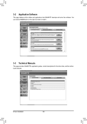
You can click the Install button on the right of an item to install it. 3-3 Technical Manuals This page provides GIGABYTE's application guides, content descriptions for this driver disk, and the motherboard manuals. 3-2 Application Software This page displays all the utilities and applications that GIGABYTE develops and some free software. Drivers Installation - 56 -
You can click the Install button on the right of an item to install it. 3-3 Technical Manuals This page provides GIGABYTE's application guides, content descriptions for this driver disk, and the motherboard manuals. 3-2 Application Software This page displays all the utilities and applications that GIGABYTE develops and some free software. Drivers Installation - 56 -

Manual
Page 62
...BIOS. Unique Features - 62 - Additionally, this motherboard features the DualBIOS™ design, which enhances protection for GA-770T-D3L F3a . . . . : BIOS Setup : XpressRecovery2 : Boot Menu : Qflash 06/30/2010-RX780-SB710...access Q-Flash by adding one more physical BIOS chip. What is Q-Flash™? From GIGABYTE's website, download the latest compressed BIOS update file that support DualBIOS have two BIOS ...latest BIOS file from the hassles of system safety, users cannot update the backup BIOS manually. Extract the file and save the new BIOS file (e.g. 770TD3L.f1) to enter ...
...BIOS. Unique Features - 62 - Additionally, this motherboard features the DualBIOS™ design, which enhances protection for GA-770T-D3L F3a . . . . : BIOS Setup : XpressRecovery2 : Boot Menu : Qflash 06/30/2010-RX780-SB710...access Q-Flash by adding one more physical BIOS chip. What is Q-Flash™? From GIGABYTE's website, download the latest compressed BIOS update file that support DualBIOS have two BIOS ...latest BIOS file from the hassles of system safety, users cannot update the backup BIOS manually. Extract the file and save the new BIOS file (e.g. 770TD3L.f1) to enter ...
Manual
Page 65
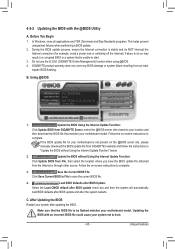
... the BIOS with the @BIOS Utility A. Unique Features Failure to do NOT interrupt the Internet connection (for your motherboard model. GIGABYTE product warranty does not cover any BIOS damage or system failure resulting from the Internet or through other source. If the BIOS update...update. 2. Update the BIOS without Using the Internet Update Function" below. 2. Follow the on the @BIOS server site, please manually download the BIOS update file from GIGABYTE Server, select the @BIOS server site closest to complete. 3. 4-2-2 Updating the BIOS with an incorrect BIOS file could cause ...
... the BIOS with the @BIOS Utility A. Unique Features Failure to do NOT interrupt the Internet connection (for your motherboard model. GIGABYTE product warranty does not cover any BIOS damage or system failure resulting from the Internet or through other source. If the BIOS update...update. 2. Update the BIOS without Using the Internet Update Function" below. 2. Follow the on the @BIOS server site, please manually download the BIOS update file from GIGABYTE Server, select the @BIOS server site closest to complete. 3. 4-2-2 Updating the BIOS with an incorrect BIOS file could cause ...
Manual
Page 76
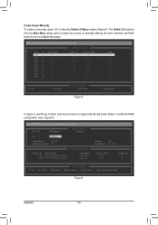
...the Define LD Menu window (Figure 4). LD 7 ---- The Define LD selection from the Main Menu allows users to begin the process of manually defining the drive elements and RAID levels for one or multiple disk arrays. Option ROM Utility (c) 2010 Advanced Micro Devices, Inc. [ ...Utility (c) 2010 Advanced Micro Devices, Inc. LD No RAID Mode [ Define LD Menu ] Total Drv LD 1 RAID 0 0 Stripe Block: 64 KB Gigabyte Boundary: ON [ Drives Assignments ] Channel:ID Drive Model 1:Mas WDC WD800JD-22LSA0 2:Mas WDC WD800JD-22LSA0 Capabilities SATA 3G SATA 3G Fast Init: ON...
...the Define LD Menu window (Figure 4). LD 7 ---- The Define LD selection from the Main Menu allows users to begin the process of manually defining the drive elements and RAID levels for one or multiple disk arrays. Option ROM Utility (c) 2010 Advanced Micro Devices, Inc. [ ...Utility (c) 2010 Advanced Micro Devices, Inc. LD No RAID Mode [ Define LD Menu ] Total Drv LD 1 RAID 0 0 Stripe Block: 64 KB Gigabyte Boundary: ON [ Drives Assignments ] Channel:ID Drive Model 1:Mas WDC WD800JD-22LSA0 2:Mas WDC WD800JD-22LSA0 Capabilities SATA 3G SATA 3G Fast Init: ON...
Manual
Page 85
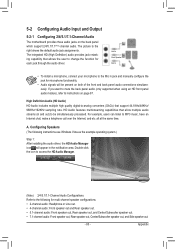
... which support 2/4/5.1/7.1(Note)-channel audio. Line In Front Speaker Out Mic In • To install a microphone, connect your microphone to the Mic in jack and manually configure the jack for microphone functionality. • Audio signals will appear in and out) to change the function for multi-channel speaker configurations. • 2-channel...
... which support 2/4/5.1/7.1(Note)-channel audio. Line In Front Speaker Out Mic In • To install a microphone, connect your microphone to the Mic in jack and manually configure the jack for microphone functionality. • Audio signals will appear in and out) to change the function for multi-channel speaker configurations. • 2-channel...


