Manual
Page 3
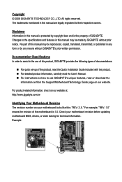
...on our website. For product-related information, check on our website at: http://www.gigabyte.com.tw Identifying Your Motherboard Revision The revision number on your motherboard revision before updating motherboard BIOS, drivers, or when looking for technical information. For example, "REV: 1.0" means ...the revision of the motherboard is the property of this manual may be made by any form or by GIGABYTE without GIGABYTE's prior written permission. ...
...on our website. For product-related information, check on our website at: http://www.gigabyte.com.tw Identifying Your Motherboard Revision The revision number on your motherboard revision before updating motherboard BIOS, drivers, or when looking for technical information. For example, "REV: 1.0" means ...the revision of the motherboard is the property of this manual may be made by any form or by GIGABYTE without GIGABYTE's prior written permission. ...
Manual
Page 4
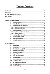
Table of Contents Box Contents ...6 Optional Items...6 GA-EX58-UD4 Motherboard Layout 7 Block Diagram...8 Chapter 1 Hardware Installation 9 1-1 Installation Precautions 9 1-2 Product Specifications 10 1-3 Installing the CPU and CPU Cooler 13 1-3-1 ... Installing the SATA Bracket 19 1-7 Back Panel Connectors 20 1-8 Internal Connectors 22 Chapter 2 BIOS Setup 35 2-1 Startup Screen 36 2-2 The Main Menu 37 2-3 MB Intelligent Tweaker(M.I.T 39 2-4 Standard CMOS Features 49 2-5 Advanced BIOS Features 51 2-6 Integrated Peripherals 53 2-7 Power Management Setup 56 2-8 PC Health Status 58 ...
Table of Contents Box Contents ...6 Optional Items...6 GA-EX58-UD4 Motherboard Layout 7 Block Diagram...8 Chapter 1 Hardware Installation 9 1-1 Installation Precautions 9 1-2 Product Specifications 10 1-3 Installing the CPU and CPU Cooler 13 1-3-1 ... Installing the SATA Bracket 19 1-7 Back Panel Connectors 20 1-8 Internal Connectors 22 Chapter 2 BIOS Setup 35 2-1 Startup Screen 36 2-2 The Main Menu 37 2-3 MB Intelligent Tweaker(M.I.T 39 2-4 Standard CMOS Features 49 2-5 Advanced BIOS Features 51 2-6 Integrated Peripherals 53 2-7 Power Management Setup 56 2-8 PC Health Status 58 ...
Manual
Page 5
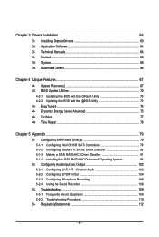
... Download Center 66 Chapter 4 Unique Features 67 4-1 Xpress Recovery2 67 4-2 BIOS Update Utilities 70 4-2-1 Updating the BIOS with the Q-Flash Utility 70 4-2-2 Updating the BIOS with the @BIOS Utility 73 4-3 EasyTune 6...74 4-4 Dynamic Energy Saver Advanced 75 4-5 Q-...Share ...77 4-6 Time Repair ...78 Chapter 5 Appendix ...79 5-1 Configuring SATA Hard Drive(s 79 5-1-1 Configuring Intel ICH10R SATA Controllers 79 5-1-2 Configuring GIGABYTE...
... Download Center 66 Chapter 4 Unique Features 67 4-1 Xpress Recovery2 67 4-2 BIOS Update Utilities 70 4-2-1 Updating the BIOS with the Q-Flash Utility 70 4-2-2 Updating the BIOS with the @BIOS Utility 73 4-3 EasyTune 6...74 4-4 Dynamic Energy Saver Advanced 75 4-5 Q-...Share ...77 4-6 Time Repair ...78 Chapter 5 Appendix ...79 5-1 Configuring SATA Hard Drive(s 79 5-1-1 Configuring Intel ICH10R SATA Controllers 79 5-1-2 Configuring GIGABYTE...
Manual
Page 8
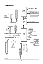
... PCIe CLK (100 MHz) x1 LAN RJ45 RTL 8111D x1 PCI Express Bus 2 SATA 3Gb/s ATA-133/100/66/33 IDE Channel PCI Bus x1 GIGABYTE SATA2 TSB43AB23 LGA1366 Processor CPU CLK+/- (133 MHz) DDR3 2000/1333/1066/800 MHz Dual/3 Channel Memory QPI Interface Intel® X58 IOH CLK (133... MHz) Intel® ICH10R Dual BIOS 6 SATA 3Gb/s 12 USB Ports LPC Bus IT8720 Floppy COM Port 3 IEEE 1394a CODEC PS/2 KB/Mouse Surround Speaker Out Center/Subwoofer Speaker Out Side...
... PCIe CLK (100 MHz) x1 LAN RJ45 RTL 8111D x1 PCI Express Bus 2 SATA 3Gb/s ATA-133/100/66/33 IDE Channel PCI Bus x1 GIGABYTE SATA2 TSB43AB23 LGA1366 Processor CPU CLK+/- (133 MHz) DDR3 2000/1333/1066/800 MHz Dual/3 Channel Memory QPI Interface Intel® X58 IOH CLK (133... MHz) Intel® ICH10R Dual BIOS 6 SATA 3Gb/s 12 USB Ports LPC Bus IT8720 Floppy COM Port 3 IEEE 1394a CODEC PS/2 KB/Mouse Surround Speaker Out Center/Subwoofer Speaker Out Side...
Manual
Page 12
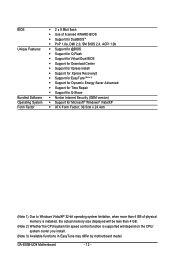
... Software Operating System Form Factor 2 x 8 Mbit flash Use of licensed AWARD BIOS Support for DualBIOSTM PnP 1.0a, DMI 2.0, SM BIOS 2.4, ACPI 1.0b Support for @BIOS Support for Q-Flash Support for Virtual Dual BIOS Support for Download Center Support for Xpress Install Support for Xpress... fan speed control function is supported will depend on the CPU/ system cooler you install. (Note 3) Available functions in EasyTune may differ by motherboard model. GA-EX58-UD4 Motherboard - 12 -
... Software Operating System Form Factor 2 x 8 Mbit flash Use of licensed AWARD BIOS Support for DualBIOSTM PnP 1.0a, DMI 2.0, SM BIOS 2.4, ACPI 1.0b Support for @BIOS Support for Q-Flash Support for Virtual Dual BIOS Support for Download Center Support for Xpress Install Support for Xpress... fan speed control function is supported will depend on the CPU/ system cooler you install. (Note 3) Available functions in EasyTune may differ by motherboard model. GA-EX58-UD4 Motherboard - 12 -
Manual
Page 16
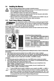
...to install the memory: • Make sure that memory of the same capacity, brand, speed, and chips be used. (Go to GIGABYTE's website for the latest memory support list.) • Always turn off the computer and unplug the power cord from the power outlet before... switch the direction. 1-4-1 Dual/3 Channel Memory Configuration This motherboard provides six DDR3 memory sockets and supports Dual/3 Channel Technology. DS/SS - - GA-EX58-UD4 Motherboard - 16 - It is installed, the BIOS will appear during the POST. DS/SS DS/SS DS/SS DS/SS DS/SS - - DS/SS - - - - Dual Channel-1. ...
...to install the memory: • Make sure that memory of the same capacity, brand, speed, and chips be used. (Go to GIGABYTE's website for the latest memory support list.) • Always turn off the computer and unplug the power cord from the power outlet before... switch the direction. 1-4-1 Dual/3 Channel Memory Configuration This motherboard provides six DDR3 memory sockets and supports Dual/3 Channel Technology. DS/SS - - GA-EX58-UD4 Motherboard - 16 - It is installed, the BIOS will appear during the POST. DS/SS DS/SS DS/SS DS/SS DS/SS - - DS/SS - - - - Dual Channel-1. ...
Manual
Page 18
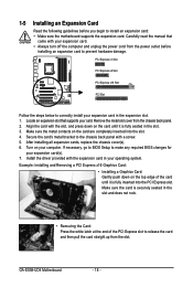
... installing all expansion cards, replace the chassis cover(s). 6. If necessary, go to BIOS Setup to make any required BIOS changes for your computer. 1-5 Installing an Expansion Card Read the following guidelines before installing an expansion card to prevent hardware damage. Make sure the card is securely seated in the slot. 3. GA-EX58-UD4 Motherboard - 18 -
... installing all expansion cards, replace the chassis cover(s). 6. If necessary, go to BIOS Setup to make any required BIOS changes for your computer. 1-5 Installing an Expansion Card Read the following guidelines before installing an expansion card to prevent hardware damage. Make sure the card is securely seated in the slot. 3. GA-EX58-UD4 Motherboard - 18 -
Manual
Page 27
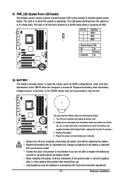
... the battery. 4. You may be handled in accordance with an equivalent one minute. (Or use a metal object like a screwdriver to keep the values (such as BIOS configurations, date, and time information) in S1 sleep state. Hardware Installation The LED keeps blinking when the system is in the power cord and restart...
... the battery. 4. You may be handled in accordance with an equivalent one minute. (Or use a metal object like a screwdriver to keep the values (such as BIOS configurations, date, and time information) in S1 sleep state. Hardware Installation The LED keeps blinking when the system is in the power cord and restart...
Manual
Page 28
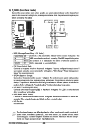
... LED, hard drive activity LED, speaker and etc. When connecting your system using the power switch (refer to Chapter 2, "BIOS Setup," "Power Management Setup," for information about beep codes. • HD (Hard Drive Activity LED, Blue) Connects to ...matched correctly. PW+ PWSPEAK+ SPEAK- 2 20 1 19 HD+ HD- The S0 On LED is detected, the BIOS may differ by issuing a beep code. The LED keeps blinking when S1 Blinking the system is detected at system startup... in S1 sleep state. Message/Power/ Power Sleep LED Switch Speaker MSG+ MSG- GA-EX58-UD4 Motherboard - 28 -
... LED, hard drive activity LED, speaker and etc. When connecting your system using the power switch (refer to Chapter 2, "BIOS Setup," "Power Management Setup," for information about beep codes. • HD (Hard Drive Activity LED, Blue) Connects to ...matched correctly. PW+ PWSPEAK+ SPEAK- 2 20 1 19 HD+ HD- The S0 On LED is detected, the BIOS may differ by issuing a beep code. The LED keeps blinking when S1 Blinking the system is detected at system startup... in S1 sleep state. Message/Power/ Power Sleep LED Switch Speaker MSG+ MSG- GA-EX58-UD4 Motherboard - 28 -
Manual
Page 33
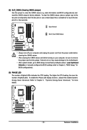
Failure to do so may cause damage to the motherboard. • After system restart, go to BIOS Setup to load factory defaults (select Load Optimized Defaults) or manually configure the BIOS settings (refer to remove the jumper cap from the jumper. The higher the CPU loading, the more details. - ..." for more the number of lighted LEDs indicates the CPU loading. date information and BIOS configurations) and reset the CMOS values to clear the CMOS values (e.g. Refer to touch the two pins for BIOS configurations). 23) PHASE LED The number of lighted LEDs. To enable the Phase LED ...
Failure to do so may cause damage to the motherboard. • After system restart, go to BIOS Setup to load factory defaults (select Load Optimized Defaults) or manually configure the BIOS settings (refer to remove the jumper cap from the jumper. The higher the CPU loading, the more details. - ..." for more the number of lighted LEDs indicates the CPU loading. date information and BIOS configurations) and reset the CMOS values to clear the CMOS values (e.g. Refer to touch the two pins for BIOS configurations). 23) PHASE LED The number of lighted LEDs. To enable the Phase LED ...
Manual
Page 35
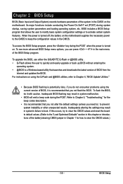
... is recommended that you can press + in the CMOS. To upgrade the BIOS, use either the GIGABYTE Q-Flash or @BIOS utility . • Q-Flash allows the user to quickly and easily upgrade or back up BIOS without entering the operating system. • @BIOS is a Windows-based utility that allows the user to modify basic system configuration...
... is recommended that you can press + in the CMOS. To upgrade the BIOS, use either the GIGABYTE Q-Flash or @BIOS utility . • Q-Flash allows the user to quickly and easily upgrade or back up BIOS without entering the operating system. • @BIOS is a Windows-based utility that allows the user to modify basic system configuration...
Manual
Page 36
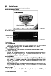
... will still be used for one time only. The POST Screen Function Keys Motherboard Model BIOS Version Award Modular BIOS v6.00PG, An Energy Star Ally Copyright (C) 1984-2008, Award Software, Inc. GA-EX58-UD4 Motherboard - 36 - EX58-UD4 D4 . . . . Function Keys: : BIOS Setup : XpressRecovery2 : Boot Menu : Qflash 11/21/2008-X58-ICH10-7A89QG09C-00 Function Keys : POST...
... will still be used for one time only. The POST Screen Function Keys Motherboard Model BIOS Version Award Modular BIOS v6.00PG, An Energy Star Ally Copyright (C) 1984-2008, Award Software, Inc. GA-EX58-UD4 Motherboard - 36 - EX58-UD4 D4 . . . . Function Keys: : BIOS Setup : XpressRecovery2 : Boot Menu : Qflash 11/21/2008-X58-ICH10-7A89QG09C-00 Function Keys : POST...
Manual
Page 37
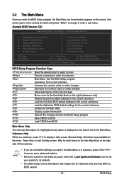
...Save & Exit Setup Exit Without Saving ESC: Quit F8: Q-Flash Select Item F10: Save & Exit Setup F11: Save CMOS to BIOS F12: Load CMOS from BIOS Change CPU's Clock & Voltage BIOS Setup Program Function Keys Move the selection bar to select an item Execute command or enter the submenu Main Menu: Exit...onscreen description of a highlighted setup option is not stable as shown below) appears on the bottom line of function keys available for the menu. BIOS Setup Press to exit the help screen (General Help) of the Main Menu. Help for each item is in the Item Help block on the...
...Save & Exit Setup Exit Without Saving ESC: Quit F8: Q-Flash Select Item F10: Save & Exit Setup F11: Save CMOS to BIOS F12: Load CMOS from BIOS Change CPU's Clock & Voltage BIOS Setup Program Function Keys Move the selection bar to select an item Execute command or enter the submenu Main Menu: Exit...onscreen description of a highlighted setup option is not stable as shown below) appears on the bottom line of function keys available for the menu. BIOS Setup Press to exit the help screen (General Help) of the Main Menu. Help for each item is in the Item Help block on the...
Manual
Page 38
...the Main Menu Only) F11 : Save CMOS to BIOS This function allows you to restrict access to the system and BIOS Setup. First enter the profile name (to erase the default profile name, use this task.) GA-EX58-UD4 Motherboard - 38 - A supervisor password allows you to restrict ...access to the confirmation message will exit BIOS Setup. (Pressing can use the SPACE key) and then press to complete. F12 : Load ...
...the Main Menu Only) F11 : Save CMOS to BIOS This function allows you to restrict access to the system and BIOS Setup. First enter the profile name (to erase the default profile name, use this task.) GA-EX58-UD4 Motherboard - 38 - A supervisor password allows you to restrict ...access to the confirmation message will exit BIOS Setup. (Pressing can use the SPACE key) and then press to complete. F12 : Load ...
Manual
Page 39
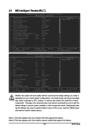
BIOS Setup If this occurs, clear the CMOS values and reset the board to default values.) (Note 1) This item appears only if you install a CPU that ...
BIOS Setup If this occurs, clear the CMOS values and reset the board to default values.) (Note 1) This item appears only if you install a CPU that ...
Manual
Page 41
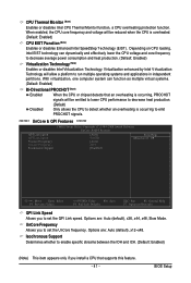
Options are : Auto (default), x36, x44, x48, Slow Mode. BIOS Setup CPU Thermal Monitor (Note) Enables or disables Intel CPU Thermal Monitor function, a CPU overheating protection function. Depending on CPU loading, Intel EIST technology can ...
Options are : Auto (default), x36, x44, x48, Slow Mode. BIOS Setup CPU Thermal Monitor (Note) Enables or disables Intel CPU Thermal Monitor function, a CPU overheating protection function. Depending on CPU loading, Intel EIST technology can ...
Manual
Page 43
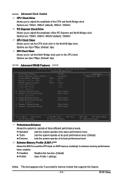
Standard Lets the system operate at its best performance level. Extreme Memory Profile (X.M.P.) (Note) Allows the BIOS to read the SPD data on XMP memory module(s) to enhance memory performance when enabled. CPU Clock Skew Allows you to set the CPU ... Save F6: Fail-Safe Defaults ESC: Exit F1: General Help F7: Optimized Defaults Performance Enhance Allows the system to operate at its basic performance level. BIOS Setup PCI Express Clock Drive Allows you install a memory module that supports this feature. - 43 - Turbo Lets the system operate at its good performance ...
Standard Lets the system operate at its best performance level. Extreme Memory Profile (X.M.P.) (Note) Allows the BIOS to read the SPD data on XMP memory module(s) to enhance memory performance when enabled. CPU Clock Skew Allows you to set the CPU ... Save F6: Fail-Safe Defaults ESC: Exit F1: General Help F7: Optimized Defaults Performance Enhance Allows the system to operate at its basic performance level. BIOS Setup PCI Express Clock Drive Allows you install a memory module that supports this feature. - 43 - Turbo Lets the system operate at its good performance ...
Manual
Page 45
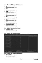
... F6: Fail-Safe Defaults >>>>> Channel A/B/C Writes Followed by Reads Different DIMMs Options are : Auto (default), 1~31. ESC: Exit F1: General Help F7: Optimized Defaults - 45 - BIOS Setup tWR Options are : Auto (default), 1~8. >>>>> Channel A/B/C Advanced Timing Control tRC Options are : Auto (default), 1~31. tWTR Options are : Auto (default), 1~63.
... F6: Fail-Safe Defaults >>>>> Channel A/B/C Writes Followed by Reads Different DIMMs Options are : Auto (default), 1~31. ESC: Exit F1: General Help F7: Optimized Defaults - 45 - BIOS Setup tWR Options are : Auto (default), 1~8. >>>>> Channel A/B/C Advanced Timing Control tRC Options are : Auto (default), 1~31. tWTR Options are : Auto (default), 1~63.
Manual
Page 47
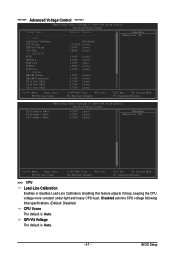
...: General Help F7: Optimized Defaults >>> CPU Load-Line Calibration Enables or disables Load-Line Calibration. Ch-B Address VRef. QPI/Vtt Voltage The default is Auto. BIOS Setup Disabled sets the CPU voltage following Intel specifications. (Default: Disabled) CPU Vcore The default is Auto. - 47 - ******* Advanced Voltage Control ******* CMOS Setup Utility-Copyright...
...: General Help F7: Optimized Defaults >>> CPU Load-Line Calibration Enables or disables Load-Line Calibration. Ch-B Address VRef. QPI/Vtt Voltage The default is Auto. BIOS Setup Disabled sets the CPU voltage following Intel specifications. (Default: Disabled) CPU Vcore The default is Auto. - 47 - ******* Advanced Voltage Control ******* CMOS Setup Utility-Copyright...
Manual
Page 49
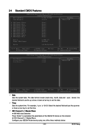
... the date. Select the desired field and use the up arrow or down arrow key to autodetect the parameters of the three methods below: - 49 - BIOS Setup IDE Channel 0, 1 Master/Slave Configure your IDE/SATA devices by using one of the IDE/SA TA device on this channel. IDE Channel 0, 1 Master...
... the date. Select the desired field and use the up arrow or down arrow key to autodetect the parameters of the three methods below: - 49 - BIOS Setup IDE Channel 0, 1 Master/Slave Configure your IDE/SATA devices by using one of the IDE/SA TA device on this channel. IDE Channel 0, 1 Master...


