Manual
Page 1
MN525RI MN525MI Intel® D525 Processor Motherboards User's Manual Rev. 1001
MN525RI MN525MI Intel® D525 Processor Motherboards User's Manual Rev. 1001
Manual
Page 3
Table of Contents MN525RI Motherboard Layout 4 Chapter 1 Hardware Installation 6 1-1 Installation Precautions 6 1-2 Product Specifications 7 1-3 Installing the Memory 9 1-3-1 Dual Channel Memory Configuration 9 1-3-2 Installing a Memory 10 1-4 Back Panel Connectors 11 1-5 Internal Connectors 12 - 3 -
Table of Contents MN525RI Motherboard Layout 4 Chapter 1 Hardware Installation 6 1-1 Installation Precautions 6 1-2 Product Specifications 7 1-3 Installing the Memory 9 1-3-1 Dual Channel Memory Configuration 9 1-3-2 Installing a Memory 10 1-4 Back Panel Connectors 11 1-5 Internal Connectors 12 - 3 -
Manual
Page 4
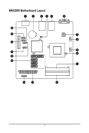
MN525RI Motherboard Layout - 4 -
MN525RI Motherboard Layout - 4 -
Manual
Page 6
...a result of the product, please consult a certified computer technician. - 6 - If you are connected tightly and securely. • When handling the motherboard, avoid touching any installation steps or have a problem related to installation, do not have an ESD wrist strap, keep your hands dry and first touch ...discharge (ESD). These stickers are required for warranty validation. • Always remove the AC power by unplugging the power cord from the motherboard, make sure the power supply has been turned off. • Before turning on the power, make sure the power supply voltage has...
...a result of the product, please consult a certified computer technician. - 6 - If you are connected tightly and securely. • When handling the motherboard, avoid touching any installation steps or have a problem related to installation, do not have an ESD wrist strap, keep your hands dry and first touch ...discharge (ESD). These stickers are required for warranty validation. • Always remove the AC power by unplugging the power cord from the motherboard, make sure the power supply has been turned off. • Before turning on the power, make sure the power supply voltage has...
Manual
Page 9
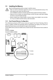
A memory module can be used. (Go to GIGABYTE's website for the latest supported memory speeds and memory modules.) • Always turn off the computer and unplug the power cord from the power outlet ... to prevent hardware damage. • Memory modules have a foolproof design. If you begin to insert the memory, switch the direction. 1-3-1 Dual Channel Memory Configuration This motherboard provides four DDR3 memory sockets and supports Dual Channel Technology. Enabling Dual Channel memory mode will automatically detect the specifications and capacity of the same...
A memory module can be used. (Go to GIGABYTE's website for the latest supported memory speeds and memory modules.) • Always turn off the computer and unplug the power cord from the power outlet ... to prevent hardware damage. • Memory modules have a foolproof design. If you begin to insert the memory, switch the direction. 1-3-1 Dual Channel Memory Configuration This motherboard provides four DDR3 memory sockets and supports Dual Channel Technology. Enabling Dual Channel memory mode will automatically detect the specifications and capacity of the same...
Manual
Page 10
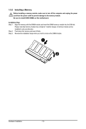
... memory module into the DIM slot. Reverse the installation steps when you wish to the memory module. Be sure to install DDR3 DIMMs on this motherboard.
... memory module into the DIM slot. Reverse the installation steps when you wish to the memory module. Be sure to install DDR3 DIMMs on this motherboard.
Manual
Page 11
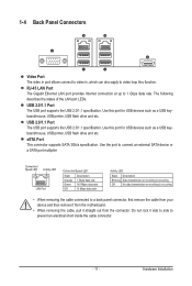
... an electrical short inside the cable connector. - 11 - USB 2.0/1.1 Port The USB port supports the USB 2.0/1.1 specification. Do not rock it straight out from the motherboard. • When removing the cable, pull it side to side to 1 Gbps data rate. The following describes the states of the LAN port LEDs. Use...
... an electrical short inside the cable connector. - 11 - USB 2.0/1.1 Port The USB port supports the USB 2.0/1.1 specification. Do not rock it straight out from the motherboard. • When removing the cable, pull it side to side to 1 Gbps data rate. The following describes the states of the LAN port LEDs. Use...

Manual
Page 12
1-5 Internal Connectors 1) ATX 2) ATX_12V 3) FAN1 4) FAN2 5) SATAII1~5 6) F_PANEL 7) F_USB1 8) F_USB2 9) COM 10) 80H 11) BAT 12) CLR_CMOS Read the following guidelines before turning on the motherboard. Hardware Installation - 12 - Unplug the power cord from the power outlet to prevent damage to the devices. • After installing the device and before connecting ...
1-5 Internal Connectors 1) ATX 2) ATX_12V 3) FAN1 4) FAN2 5) SATAII1~5 6) F_PANEL 7) F_USB1 8) F_USB2 9) COM 10) 80H 11) BAT 12) CLR_CMOS Read the following guidelines before turning on the motherboard. Hardware Installation - 12 - Unplug the power cord from the power outlet to prevent damage to the devices. • After installing the device and before connecting ...
Manual
Page 13
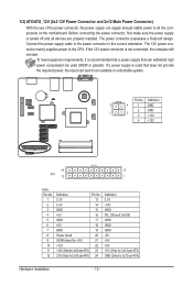
... the power supply is not connected, the computer will not start. If the 12V power connector is turned off and all the components on the motherboard.
... the power supply is not connected, the computer will not start. If the 12V power connector is turned off and all the components on the motherboard.
Manual
Page 14
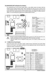
... header according to prevent your CPU and system from overheating. MSG- ACT+ ACT+ ACT- RST+ PW+ RST- 2/3) FAN1/FAN2 (CPU Fan/System Fan Headers) The motherboard has a 4-pin CPU fan header (FAN1), a 4-pin (FAN2) system fan headers. FAN1 FAN2 FAN1 FAN2 FAN1 (CPU Fan): Pin No. The...
... header according to prevent your CPU and system from overheating. MSG- ACT+ ACT+ ACT- RST+ PW+ RST- 2/3) FAN1/FAN2 (CPU Fan/System Fan Headers) The motherboard has a 4-pin CPU fan header (FAN1), a 4-pin (FAN2) system fan headers. FAN1 FAN2 FAN1 FAN2 FAN1 (CPU Fan): Pin No. The...
Manual
Page 18
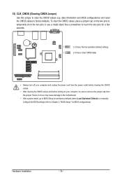
... the CMOS values and before turning on your computer, be sure to clear the CMOS values (e.g. Failure to do so may cause damage to the motherboard. • After system restart, go to BIOS Setup to load factory defaults (select Load Optimized Defaults) or manually configure the BIOS settings (refer to factory...
... the CMOS values and before turning on your computer, be sure to clear the CMOS values (e.g. Failure to do so may cause damage to the motherboard. • After system restart, go to BIOS Setup to load factory defaults (select Load Optimized Defaults) or manually configure the BIOS settings (refer to factory...


