
Manual
Page 10
... 0x55 Command format: raw : 0x69 0x6d 0x61 0x67 0x65 0x2e 0x52 0x42 0x55 = image.RBU [5] Check upload status e.g. ipmitool -H 10.1.27.150 -U admin -P password raw 0x2e 0x21 0x0a 0x3c 0x00 0x0e Response: 0a 3c 00 01 00 Byte 1 = 00h : Command Completed Normally Byte 2 = 01h : Copying To Scratch Byte 3 = 00h : Update Progress (If byte 2 is 06, this data...
... 0x55 Command format: raw : 0x69 0x6d 0x61 0x67 0x65 0x2e 0x52 0x42 0x55 = image.RBU [5] Check upload status e.g. ipmitool -H 10.1.27.150 -U admin -P password raw 0x2e 0x21 0x0a 0x3c 0x00 0x0e Response: 0a 3c 00 01 00 Byte 1 = 00h : Command Completed Normally Byte 2 = 01h : Copying To Scratch Byte 3 = 00h : Update Progress (If byte 2 is 06, this data...

Manual
Page 3
... Console (Linux 13 1-5-1 Tomcat Installation Procedure 13 1-5-2 PostgreSQL Installation Procedure 13 1-5-3 Restore dbRMCv0XX.backup 14 1-5-4 pgadminIII Installation Procedure (Optional 15 1-5-5 Login Gigabyte Server Management Console 16 Chapter 2 Gigabyte Server Management Console 17 2-1 Overview...17 2-2 Enter Gigabyte Server Management Console 18 2-2-1 Node Info...18 2-2-1-1 Node ID...20 Power Consumption...20 SEL ...21 Node Detail...21 Chassis ...22 Sensor ...23 Trap IP Destination List...24 Platform Events...25 BMC Update...26 BIOS Update...26 Power Limit...27 IPv6 Configuration...
... Console (Linux 13 1-5-1 Tomcat Installation Procedure 13 1-5-2 PostgreSQL Installation Procedure 13 1-5-3 Restore dbRMCv0XX.backup 14 1-5-4 pgadminIII Installation Procedure (Optional 15 1-5-5 Login Gigabyte Server Management Console 16 Chapter 2 Gigabyte Server Management Console 17 2-1 Overview...17 2-2 Enter Gigabyte Server Management Console 18 2-2-1 Node Info...18 2-2-1-1 Node ID...20 Power Consumption...20 SEL ...21 Node Detail...21 Chassis ...22 Sensor ...23 Trap IP Destination List...24 Platform Events...25 BMC Update...26 BIOS Update...26 Power Limit...27 IPv6 Configuration...

Manual
Page 38
... power limit fail Get SEL fail Get SDR fail Set trap IP/enable destination fail Set platform events fail Set IPv6 trap IP/enable destination fail Get platform events fail Get IPv6 trap IP/enable destination fail Match rack node info fail Match RMC/BMC IP fail Get FRU fail Save Event Log to log file fail Copy catalina file fail Close file channel fail Get power status fail Send chassis command fail Set IPv6 enable/disable configuration fail Get power reading fail Get CPU temperature fail Set boot option fail Set chassis identify fail Power limit deactivate Description Network is not connected...
... power limit fail Get SEL fail Get SDR fail Set trap IP/enable destination fail Set platform events fail Set IPv6 trap IP/enable destination fail Get platform events fail Get IPv6 trap IP/enable destination fail Match rack node info fail Match RMC/BMC IP fail Get FRU fail Save Event Log to log file fail Copy catalina file fail Close file channel fail Get power status fail Send chassis command fail Set IPv6 enable/disable configuration fail Get power reading fail Get CPU temperature fail Set boot option fail Set chassis identify fail Power limit deactivate Description Network is not connected...

Manual
Page 2
... Management Network Configuration 6 Using the Web UI...8 Gigabyte Content Management System Console Overview 9 Enter Gigabyte Content Management System Console 10 Properties ...10 Configuration ...11 Network...11 Network Security ...12 Security ...13 Users ...14 Services ...15 IPMI ...16 Time Setting ...18 Language ...19 Sessions ...20 LDAP ...21 Updates ...22 Utilities ...23 Server Information ...24 General Setting...24 Power Control ...25 Power Consumption ...26 System Event Log ...27 Event Management ...28 Platform Event ...28 Trap Settings ...29 Email Settings ...30 Serial Over LAN...
... Management Network Configuration 6 Using the Web UI...8 Gigabyte Content Management System Console Overview 9 Enter Gigabyte Content Management System Console 10 Properties ...10 Configuration ...11 Network...11 Network Security ...12 Security ...13 Users ...14 Services ...15 IPMI ...16 Time Setting ...18 Language ...19 Sessions ...20 LDAP ...21 Updates ...22 Utilities ...23 Server Information ...24 General Setting...24 Power Control ...25 Power Consumption ...26 System Event Log ...27 Event Management ...28 Platform Event ...28 Trap Settings ...29 Email Settings ...30 Serial Over LAN...

Manual
Page 12
... BMC related settings through the BMC port. 2. Select the Network Mode from the drop-down list. 1. Configuration Network You can configure the BMC related settings through the BMC or NIC2 port. (Backup Mode) When you finish configuration, click Apply Change. Shared Mode When set to Failover Mode, you can configure the BMC related settings through the NIC2 port. (Shared NIC Mode) 3. Dedicate Mode When set to take effect immediately, click "Refresh" to Shared Mode, you can view and modify the network settings...
... BMC related settings through the BMC port. 2. Select the Network Mode from the drop-down list. 1. Configuration Network You can configure the BMC related settings through the BMC or NIC2 port. (Backup Mode) When you finish configuration, click Apply Change. Shared Mode When set to Failover Mode, you can configure the BMC related settings through the NIC2 port. (Shared NIC Mode) 3. Dedicate Mode When set to take effect immediately, click "Refresh" to Shared Mode, you can view and modify the network settings...

Manual
Page 17
... be configured to manage the system from the drop-down list. Operator All BMC commands are four serial configuration in IPMI Serial: Connection Mode Settings, Baud Rate, Flow Control, and Channel Privilege Level Limit. Users This may be executed. IPMI Serial There are allowed, except for configuration commands that the Administrator is set, select the Baud Rate and Flow Control from a remote location. The Connection Mode Settings allows user to select the Console redirection type and to operate...
... be configured to manage the system from the drop-down list. Operator All BMC commands are four serial configuration in IPMI Serial: Connection Mode Settings, Baud Rate, Flow Control, and Channel Privilege Level Limit. Users This may be executed. IPMI Serial There are allowed, except for configuration commands that the Administrator is set, select the Baud Rate and Flow Control from a remote location. The Connection Mode Settings allows user to select the Console redirection type and to operate...

Manual
Page 4
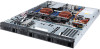
... Hardware Installation 16 2-1 Removing Chassis Cover 17 2-2 Removing and Installing the Fan Duct 18 2-3 Installing the CPU 19 2-4 Installing the Heat Sink 20 2-5 Installing the Memory 21 2-5-1 Four Channel Memory Configuration 21 2-5-2 Installing a Memory 22 2-5-3 DIMM Population Table 22 2-6 Installing the PCI Expansion Card 23 2-7 Installing the Hard Disk Drive 24 2-8 Replacing the FAN Assemblly 25 2-9 Replacing the Power Supply 26 Chapter 3 System Appearance 27 3-1 Front View...27 3-2 Rear View...27 3-3 Front Panel LED and Buttons 28 3-4 Rear System LAN LEDs 30 3-5 Hard Disk...
... Hardware Installation 16 2-1 Removing Chassis Cover 17 2-2 Removing and Installing the Fan Duct 18 2-3 Installing the CPU 19 2-4 Installing the Heat Sink 20 2-5 Installing the Memory 21 2-5-1 Four Channel Memory Configuration 21 2-5-2 Installing a Memory 22 2-5-3 DIMM Population Table 22 2-6 Installing the PCI Expansion Card 23 2-7 Installing the Hard Disk Drive 24 2-8 Replacing the FAN Assemblly 25 2-9 Replacing the Power Supply 26 Chapter 3 System Appearance 27 3-1 Front View...27 3-2 Rear View...27 3-3 Front Panel LED and Buttons 28 3-4 Rear System LAN LEDs 30 3-5 Hard Disk...

Manual
Page 8
... any kind into the network interface controller (NIC) receptacle. • Disconnect the modem cable before opening a product enclosure, touching or installing internalcompo- The equipment grounding should be operated only from the type of electri- Do not block or cover these openings. Precaution for Product with local and nationalelectrical codes. There may be accessible at the factory to the correct voltage. • The plug-socket...
... any kind into the network interface controller (NIC) receptacle. • Disconnect the modem cable before opening a product enclosure, touching or installing internalcompo- The equipment grounding should be operated only from the type of electri- Do not block or cover these openings. Precaution for Product with local and nationalelectrical codes. There may be accessible at the factory to the correct voltage. • The plug-socket...
Manual
Page 28
...; Processor or terminator missing N/A HDD locate N/A HDD access N/A HDD fault N/A HDD rebuilding N/A • • No HDD access No HDD fault N/A Link between system and network or no access N/A Data transmission or receiving is occurring No data transmission or N/A receiving is occurring N/A Link between system and network or no access N/A Data transmission or receiving is occurring N/A No data transmission or receiving is operating normally. Name 1 System Status LED 2. Hardware Installation 3-3 Front Panel LED and Buttons...
...; Processor or terminator missing N/A HDD locate N/A HDD access N/A HDD fault N/A HDD rebuilding N/A • • No HDD access No HDD fault N/A Link between system and network or no access N/A Data transmission or receiving is occurring No data transmission or N/A receiving is occurring N/A Link between system and network or no access N/A Data transmission or receiving is occurring N/A No data transmission or receiving is operating normally. Name 1 System Status LED 2. Hardware Installation 3-3 Front Panel LED and Buttons...
Manual
Page 35
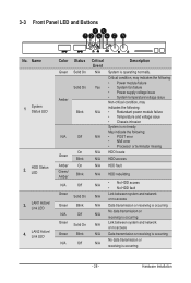
... pins (Default setting), in order to Page 37 for Primary CPU) Clear CMOS jumper SAS SGPIO header#1 Mini-SAS cable connector#1 supports SATA3 6Gb/s Mini-SAS cable connector#2 supports SATA3 6Gb/s PCI Express x8 slot Case open intrusion alert header ME update jumper Clearing Supervisor Password jumper BIOS recovery jumper ME recovery jumper S3 Power On Select jumper Intel/LSI Software RAID Key jumper PCI Express x16 slot PCI Express x8 slot (Shared bandwidth with PCIE_3) PCI Express x16 slot PCI Express x8 slot BMC Management LAN port link LED header BMC Management LAN port active LED header...
... pins (Default setting), in order to Page 37 for Primary CPU) Clear CMOS jumper SAS SGPIO header#1 Mini-SAS cable connector#1 supports SATA3 6Gb/s Mini-SAS cable connector#2 supports SATA3 6Gb/s PCI Express x8 slot Case open intrusion alert header ME update jumper Clearing Supervisor Password jumper BIOS recovery jumper ME recovery jumper S3 Power On Select jumper Intel/LSI Software RAID Key jumper PCI Express x16 slot PCI Express x8 slot (Shared bandwidth with PCIE_3) PCI Express x16 slot PCI Express x8 slot BMC Management LAN port link LED header BMC Management LAN port active LED header...
Manual
Page 41
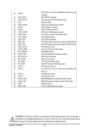
... the items in standard compatible BIOS. Advanced This setup page includes all the items of AMI BIOS special enhanced features. (ex: Auto detect fan and temperature status, automatically configure hard disk parameters.) Intel RC Setup This setup page includes all the submenu options for configuration of processor, network, North Bridge, South Bridge, and System event logs. Server Management Server additional features enabled/disabled setup menus. Security Change, set, or disable supervisor and user password.
... the items in standard compatible BIOS. Advanced This setup page includes all the items of AMI BIOS special enhanced features. (ex: Auto detect fan and temperature status, automatically configure hard disk parameters.) Intel RC Setup This setup page includes all the submenu options for configuration of processor, network, North Bridge, South Bridge, and System event logs. Server Management Server additional features enabled/disabled setup menus. Security Change, set, or disable supervisor and user password.

Manual
Page 55
... is useful when any RT code is Upon Request. Default setting is executed above 1MB. Default setting is Enabled. Options available: Enabled/Disabled. Default setting is UEFI and Legacy. - 55 - Gate20 Active Upon Request: GA20 can be disabled using BIOS services. Options available: UEFI and Legacy/Legacy only/UEFI only. Option ROM Messages Option ROM Messages. INT19 Endless Retry Enabled: Allowed headless retry boot Options available: Enabled/Disabled. 5-2-4 CSM Configuration Compatibility Support Module Configuration CSM Support Enable/Disable Compatibility Support Module (CSM...
... is useful when any RT code is Upon Request. Default setting is executed above 1MB. Default setting is Enabled. Options available: Enabled/Disabled. Default setting is UEFI and Legacy. - 55 - Gate20 Active Upon Request: GA20 can be disabled using BIOS services. Options available: UEFI and Legacy/Legacy only/UEFI only. Option ROM Messages Option ROM Messages. INT19 Endless Retry Enabled: Allowed headless retry boot Options available: Enabled/Disabled. 5-2-4 CSM Configuration Compatibility Support Module Configuration CSM Support Enable/Disable Compatibility Support Module (CSM...

Manual
Page 68
... support function. Options available: Enabled/Disabled. This will not restrict code execution in pairs. Default setting is fetched. Hardware Prefetcher Select whether to execute two or more vulnerable to buffer overflow attacks. When disabled, only the required cache line is Enabled. Default setting is Enabled. Options available: Enabled/Disabled. Default setting is Enabled. Processor Configuration Pre-Socket Configuration Press [Enter] for configuration of next L1 Data line based upon multiple loads in data-only memory...
... support function. Options available: Enabled/Disabled. This will not restrict code execution in pairs. Default setting is fetched. Hardware Prefetcher Select whether to execute two or more vulnerable to buffer overflow attacks. When disabled, only the required cache line is Enabled. Default setting is Enabled. Options available: Enabled/Disabled. Default setting is Enabled. Processor Configuration Pre-Socket Configuration Press [Enter] for configuration of next L1 Data line based upon multiple loads in data-only memory...
Manual
Page 79
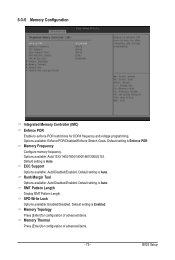
... Display RMT Pattern Length. BIOS Setup Default setting is Auto. Default setting is Enforce POR. Default setting is Auto. SPD Write Lock Options available: Enabled/Disabled. ECC Support Options available: Auto/Disabled/Enabled. Options available: Auto/1333/1400/1600/1800/1867/2000/2133. Memory Frequency Configure memory frequency. Memory Topology Press [Enter] for configuration of advanced items. Memory Thermal Press [Enter] for DDR4 frequency and voltage programming. 5-3-5 Memory Configuration Integrated Memory Controller (iMC) Enforce POR Enable...
... Display RMT Pattern Length. BIOS Setup Default setting is Auto. Default setting is Enforce POR. Default setting is Auto. SPD Write Lock Options available: Enabled/Disabled. ECC Support Options available: Auto/Disabled/Enabled. Options available: Auto/1333/1400/1600/1800/1867/2000/2133. Memory Frequency Configure memory frequency. Memory Topology Press [Enter] for configuration of advanced items. Memory Thermal Press [Enter] for DDR4 frequency and voltage programming. 5-3-5 Memory Configuration Integrated Memory Controller (iMC) Enforce POR Enable...
Manual
Page 83
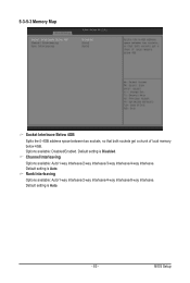
Default setting is Auto. Channel Interleaving Options available: Auto/1-way Interleave/2-way Interleave/3-way Interleave/4-way Interleave. Rank Interleaving Options available: Auto/1-way Interleave/2-way Interleave/4-way Interleave/8-way Interleave. 5-3-5-3 Memory Map Socket Interleave Below 4GB Splits the 0-4GB address space between two sockets, so that both sockets get a chunk of local memory below 4GB. Default setting is Disabled. Default setting is Auto. - 83 - Options available: Disabled/Enabled. BIOS Setup
Default setting is Auto. Channel Interleaving Options available: Auto/1-way Interleave/2-way Interleave/3-way Interleave/4-way Interleave. Rank Interleaving Options available: Auto/1-way Interleave/2-way Interleave/4-way Interleave/8-way Interleave. 5-3-5-3 Memory Map Socket Interleave Below 4GB Splits the 0-4GB address space between two sockets, so that both sockets get a chunk of local memory below 4GB. Default setting is Disabled. Default setting is Auto. - 83 - Options available: Disabled/Enabled. BIOS Setup
Manual
Page 84
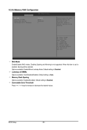
When this item is Disabled. Default setting is set to increase or decrease the desired values. Correctable Error Threshold Press / keys to enabled, Sparing will be selected. BIOS Setup - 84 - Default setting is Auto. Options available: Disable/Mirror/Lockstep Mode. Lockstep x4 DIMMs Options available: Auto/Disabled/Enabled. Default setting is Disabled. Enabling Sparing and Mirroring is not supported. 5-3-5-4 Memory RAS Configuration RAS Mode Enable/Disable RAS modes. Memory Rank Sparing Options available: Disabled/Enabled.
When this item is Disabled. Default setting is set to increase or decrease the desired values. Correctable Error Threshold Press / keys to enabled, Sparing will be selected. BIOS Setup - 84 - Default setting is Auto. Options available: Disable/Mirror/Lockstep Mode. Lockstep x4 DIMMs Options available: Auto/Disabled/Enabled. Default setting is Disabled. Enabling Sparing and Mirroring is not supported. 5-3-5-4 Memory RAS Configuration RAS Mode Enable/Disable RAS modes. Memory Rank Sparing Options available: Disabled/Enabled.
Manual
Page 91
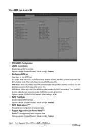
... Mode: When set to IDE PCH sSATA Configuration sSATA Controller(s) Enable/Disable sSATA controller. ACHI Mode: When set to IDE, the SATA controller disables its RAID and AHCI functions and runs in AHCI or RAID Mode. - 91 - Options available: IDE/RAID/ACHI/Disabled. Options available: Enabled/Disabled. Default setting is Disabled. SATA Test Mode Enable/Disable SATA Test Mode. Default setting is Enabled. (Note) Only Supported When HDD is in the IDE emulation mode. Default setting is Enabled. When SATA Type is disabled and cannot be allows access the RAID setup utility at boot...
... Mode: When set to IDE PCH sSATA Configuration sSATA Controller(s) Enable/Disable sSATA controller. ACHI Mode: When set to IDE, the SATA controller disables its RAID and AHCI functions and runs in AHCI or RAID Mode. - 91 - Options available: IDE/RAID/ACHI/Disabled. Options available: Enabled/Disabled. Default setting is Disabled. SATA Test Mode Enable/Disable SATA Test Mode. Default setting is Enabled. (Note) Only Supported When HDD is in the IDE emulation mode. Default setting is Enabled. When SATA Type is disabled and cannot be allows access the RAID setup utility at boot...

Manual
Page 97
...Note) Enable/Disable HDD Hot-Plug function. System will automatically detect HDD type. sSATA Device Type Select sSATA device type. Default setting is Enabled. Options available: Enabled/Disabled. BIOS Setup Options available: Enabled/Disabled. Alternate Device ID on RAID Enable /Disable Alternate Device ID on RAID mode. Support Aggressive Link Power Mana(Note) Enable PCH to the device. Default setting is Disabled. Configured as eSATA(Note) Display Hot-Plug supported information. Please note that are installed in RAID Mode. Options available: Hard Disk Drive/Solid...
...Note) Enable/Disable HDD Hot-Plug function. System will automatically detect HDD type. sSATA Device Type Select sSATA device type. Default setting is Enabled. Options available: Enabled/Disabled. BIOS Setup Options available: Enabled/Disabled. Alternate Device ID on RAID Enable /Disable Alternate Device ID on RAID mode. Support Aggressive Link Power Mana(Note) Enable PCH to the device. Default setting is Disabled. Configured as eSATA(Note) Display Hot-Plug supported information. Please note that are installed in RAID Mode. Options available: Hard Disk Drive/Solid...
Manual
Page 104
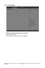
BIOS Setup - 104 - Default setting is Enabled. 5-3-10-1 Whea Setting WHEA Support (Windows Hardware Error Architecture) Enable/Disable WHEA Support. Options available: Enabled/Disabled.
BIOS Setup - 104 - Default setting is Enabled. 5-3-10-1 Whea Setting WHEA Support (Windows Hardware Error Architecture) Enable/Disable WHEA Support. Options available: Enabled/Disabled.

Manual
Page 116
BIOS setup will display an error message if the legacy drive(s) specified is Enabled. Options available: Enabled/Disabled. By default, the server searches for setup activation key. 65535(0xFFFF) means indefinite waiting." USB device BIOS Setup - 116 - 5-6 Boot Menu The Boot menu allows you to input the desired value. Press the numberic keys to set the drive priority during POST. Options available: On/Off. Quiet Boot Enables or disables showing the logo during system boot-up. UEFI device. 2. Network device. 4. Boot Configuration Setup Prompt Timeout Number of seconds to...
BIOS setup will display an error message if the legacy drive(s) specified is Enabled. Options available: Enabled/Disabled. By default, the server searches for setup activation key. 65535(0xFFFF) means indefinite waiting." USB device BIOS Setup - 116 - 5-6 Boot Menu The Boot menu allows you to input the desired value. Press the numberic keys to set the drive priority during POST. Options available: On/Off. Quiet Boot Enables or disables showing the logo during system boot-up. UEFI device. 2. Network device. 4. Boot Configuration Setup Prompt Timeout Number of seconds to...