
User Manual
Page 2
.... 6. Malfunction due to observe the instructions in the user manual. Be sure to interference from other computer-related devices. 9. The devices inside, including power supply, hard disk, CD-ROM drive, motherboard, ventilator, etc, are not covered by failure to your devices. The product's warranty label has been removed or damaged. 8. Incorrect connector installation may cause bodily harm or damage to follow...
.... 6. Malfunction due to observe the instructions in the user manual. Be sure to interference from other computer-related devices. 9. The devices inside, including power supply, hard disk, CD-ROM drive, motherboard, ventilator, etc, are not covered by failure to your devices. The product's warranty label has been removed or damaged. 8. Incorrect connector installation may cause bodily harm or damage to follow...
User Manual
Page 3
Installation Instruction 8 4-1 Installation of Power Supply 8 4-2 Installation of Motherboard 8 4-3 Installation of Add-on Card 9 4-4 Installation of Front Multi-Media I/O port 10 4-5 Connection of Fan Power Cables 11 4-6 Installation of 5.25" Front Device Bay 11 4-7 Installation of 3.5" Front Device Bay 12 4-8 Installation of Contents 1. Specifications 7 4. English Table of 3.5" Internal Device Bay 12 4-9 Foot Supports 13 4-10 Liquid Cooling System Support 13 4-11 Recommended Cooling Products 14 3 Components Introduction...
Installation Instruction 8 4-1 Installation of Power Supply 8 4-2 Installation of Motherboard 8 4-3 Installation of Add-on Card 9 4-4 Installation of Front Multi-Media I/O port 10 4-5 Connection of Fan Power Cables 11 4-6 Installation of 5.25" Front Device Bay 11 4-7 Installation of 3.5" Front Device Bay 12 4-8 Installation of Contents 1. Specifications 7 4. English Table of 3.5" Internal Device Bay 12 4-9 Foot Supports 13 4-10 Liquid Cooling System Support 13 4-11 Recommended Cooling Products 14 3 Components Introduction...
User Manual
Page 4
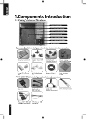
... in the accessory box) Securing Runner x 6 Copper Stand Off x 9 Motherboard Power Supply Securing Screw x 9 Securing Screw x 4 Large Wire Clamp x 2 Mini Wire Clamp x 3 Magnet Ring x 1 Dust Remover Cloth Front Cable Kit (Refer to the figures below for the cable connectors) USB 2.0 Audio Set (HD & AC'97) IEEE1394 3-Pin Fan Connector (Multi-connectors) Power SW / HDD LED 4-Pin Power LED / Speaker Connector Connector 4
... in the accessory box) Securing Runner x 6 Copper Stand Off x 9 Motherboard Power Supply Securing Screw x 9 Securing Screw x 4 Large Wire Clamp x 2 Mini Wire Clamp x 3 Magnet Ring x 1 Dust Remover Cloth Front Cable Kit (Refer to the figures below for the cable connectors) USB 2.0 Audio Set (HD & AC'97) IEEE1394 3-Pin Fan Connector (Multi-connectors) Power SW / HDD LED 4-Pin Power LED / Speaker Connector Connector 4
User Manual
Page 5
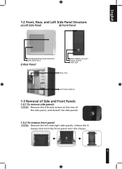
English 1-2 Front, Rear, and Left Side Panel Structure a) Left Side Panel b) Front Panel Ventilated Mesh Side Panel Kit Left Side Panel c) Rear Panel Multi-Media I/O port Power Switch HDD LED Rear Fan LCS Tube Outlets 1-3 Removal of Side and Front Panels 1-3.1 To remove side panels: 1-3.1a Remove the 4 thumb screws at the rear of the side panel, and detach the side panels. 1-3.2 To remove front panel: 1-3.2a Remove the left and right side panels, release the 4 clamps that hold the front panel onto the chassis. 5
English 1-2 Front, Rear, and Left Side Panel Structure a) Left Side Panel b) Front Panel Ventilated Mesh Side Panel Kit Left Side Panel c) Rear Panel Multi-Media I/O port Power Switch HDD LED Rear Fan LCS Tube Outlets 1-3 Removal of Side and Front Panels 1-3.1 To remove side panels: 1-3.1a Remove the 4 thumb screws at the rear of the side panel, and detach the side panels. 1-3.2 To remove front panel: 1-3.2a Remove the left and right side panels, release the 4 clamps that hold the front panel onto the chassis. 5
User Manual
Page 6
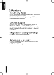
... cooling products lines Support ATX / Micro ATX / Flex ATX motherboard. -Integration of Cooling Technology Intergrated Ventilated Mesh side panel. -Convenience of Gigabyte Tech. provides users with sophisticated yet simple, precise workmanship. Tool-free installation design. 6 Illuminated and atmospherically-soothing backlight for a post-modern classy impression. -Complete Support Complete front panel multi-media support, include 2 x USB 2.0, 1 x IEEE1394, 1 x audio set (HD & AC97) Full Support of...
... cooling products lines Support ATX / Micro ATX / Flex ATX motherboard. -Integration of Cooling Technology Intergrated Ventilated Mesh side panel. -Convenience of Gigabyte Tech. provides users with sophisticated yet simple, precise workmanship. Tool-free installation design. 6 Illuminated and atmospherically-soothing backlight for a post-modern classy impression. -Complete Support Complete front panel multi-media support, include 2 x USB 2.0, 1 x IEEE1394, 1 x audio set (HD & AC97) Full Support of...
User Manual
Page 7
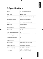
English 3.Specifications Model GZ-AA3CBI-SNS/SNB/SNG Case Type Middle Tower Size 200 x 440 x 494mm (W x H x D) Front Bezel Material Aluminum & Steel Mesh Color Silver / Black / Metallic Grey Side panel Ventilated Mesh Body material 0.7mm SECC Net weight 8.8 KG 5.25" drive bay (External) 5 3.5 drive bay (External) 2 3.5 drive bay (Internal) 3 Expansion slots 7 Form factor ATX / Micro ATX / Flex ATX System Fan (front) One 120mm silent fan System Fan (rear) One 120mm silent fan I / O Ports USB2.0 x 2 / IEEE1394 x 1 / Audio Set x 1(HD-AC'97) 7
English 3.Specifications Model GZ-AA3CBI-SNS/SNB/SNG Case Type Middle Tower Size 200 x 440 x 494mm (W x H x D) Front Bezel Material Aluminum & Steel Mesh Color Silver / Black / Metallic Grey Side panel Ventilated Mesh Body material 0.7mm SECC Net weight 8.8 KG 5.25" drive bay (External) 5 3.5 drive bay (External) 2 3.5 drive bay (Internal) 3 Expansion slots 7 Form factor ATX / Micro ATX / Flex ATX System Fan (front) One 120mm silent fan System Fan (rear) One 120mm silent fan I / O Ports USB2.0 x 2 / IEEE1394 x 1 / Audio Set x 1(HD-AC'97) 7
User Manual
Page 8
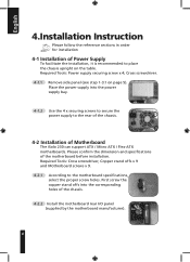
... Motherboard The iSolo 230 can support ATX / Micro ATX / Flex-ATX motherboards. Please confirm the dimension and specifications of the chassis. 4-2.2 Install the motherboard rear I/O panel (supplied by the motherboard manufacturer). 8 First screw the copper stand offs into the power supply bay. 4-1.2 Use the 4 x securing screws to secure the power supply to the motherboard specifications, select the proper screw holes. Cross screwdriver. 4-1.1 Remove side panel (see step 1-3.1 on the table. English 4.Installation Instruction...
... Motherboard The iSolo 230 can support ATX / Micro ATX / Flex-ATX motherboards. Please confirm the dimension and specifications of the chassis. 4-2.2 Install the motherboard rear I/O panel (supplied by the motherboard manufacturer). 8 First screw the copper stand offs into the power supply bay. 4-1.2 Use the 4 x securing screws to secure the power supply to the motherboard specifications, select the proper screw holes. Cross screwdriver. 4-1.1 Remove side panel (see step 1-3.1 on the table. English 4.Installation Instruction...
User Manual
Page 9
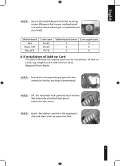
... cover. 4-3.3 Insert the add-on cards, e.g. Motherboard ATX Micro ATX Flex ATX Code name A1-A9 U1-U9 F1-F6 Motherboard screws 9 9 6 Case copper post 9 9 6 4-3 Installation of Add-on Card The iSolo 230 does not require any tools for installation of motherboard you have). English 4-2.3 Secure the motherboard with the securing screws (Please refer to your motherboard manual to check what type of add...
... cover. 4-3.3 Insert the add-on cards, e.g. Motherboard ATX Micro ATX Flex ATX Code name A1-A9 U1-U9 F1-F6 Motherboard screws 9 9 6 Case copper post 9 9 6 4-3 Installation of Add-on Card The iSolo 230 does not require any tools for installation of motherboard you have). English 4-2.3 Secure the motherboard with the securing screws (Please refer to your motherboard manual to check what type of add...
User Manual
Page 10
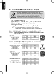
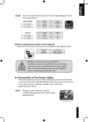
The front panel consists of: (1) 2 x USB 2.0, 1 x IEEE 1394 and 1 x Audio Set (HD & AC'97) (2) Basic casing power switch control cable kit. Required Tools: None Please refer to the instructions supplied by the motherboard manufacturer and make sure the correct type of connector is used prior to malfunction or completely destroy the motherboard. Please read the manual carefully in the installation as incorrect installations or...
The front panel consists of: (1) 2 x USB 2.0, 1 x IEEE 1394 and 1 x Audio Set (HD & AC'97) (2) Basic casing power switch control cable kit. Required Tools: None Please refer to the instructions supplied by the motherboard manufacturer and make sure the correct type of connector is used prior to malfunction or completely destroy the motherboard. Please read the manual carefully in the installation as incorrect installations or...
User Manual
Page 11
... the connectors list below for installation (see figure below) Connector Speaker Power SW HDD LED Color Yellow(+) / Black(-) Orange(+) / White(-) Red(+) / White(-) Different motherboards have different installation areas and specifications, screw holes and connectors. For detailed instructions, please refer to the motherboard user manual supplied by the motherboard manufacturer. 4-5 Connection of Fan Power Cables The iSolo 230 has one 12cm silent cooling fan in the front and...
... the connectors list below for installation (see figure below) Connector Speaker Power SW HDD LED Color Yellow(+) / Black(-) Orange(+) / White(-) Red(+) / White(-) Different motherboards have different installation areas and specifications, screw holes and connectors. For detailed instructions, please refer to the motherboard user manual supplied by the motherboard manufacturer. 4-5 Connection of Fan Power Cables The iSolo 230 has one 12cm silent cooling fan in the front and...
User Manual
Page 12
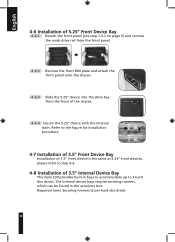
... the internal latch. English 4-6 Installation of 5.25" Front Device Bay 4-6.1 Detach the front panel (see step 1-3.2 on page 5) and remove the mesh drive rail from the front panel. 4-6.2 Remove the front EMI plate and attach the front panel onto the chassis. 4-6.3 Slide the 5.25" device into the drive bay from the front of 3.5" Internal Device Bay The iSolo 230 provides built-in the accessory...
... the internal latch. English 4-6 Installation of 5.25" Front Device Bay 4-6.1 Detach the front panel (see step 1-3.2 on page 5) and remove the mesh drive rail from the front panel. 4-6.2 Remove the front EMI plate and attach the front panel onto the chassis. 4-6.3 Slide the 5.25" device into the drive bay from the front of 3.5" Internal Device Bay The iSolo 230 provides built-in the accessory...
User Manual
Page 13
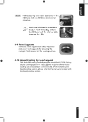
Additional HDD can fully support the GIGABYTE 3D Galaxy Liquid Cooling System (it also supports majority of the HDD and slide the HDD into the internal drive bay. While installing the liquid cooling system, please refer to secure the HDD. 4-9 Foot Supports The iSolo 230 is supplied with the liquid cooling system. 13 Slide in the 3.5" front device bay. English 4-8.1 Fit the...
Additional HDD can fully support the GIGABYTE 3D Galaxy Liquid Cooling System (it also supports majority of the HDD and slide the HDD into the internal drive bay. While installing the liquid cooling system, please refer to secure the HDD. 4-9 Foot Supports The iSolo 230 is supplied with the liquid cooling system. 13 Slide in the 3.5" front device bay. English 4-8.1 Fit the...
User Manual
Page 14
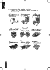
English 4-11 Recommended Cooling Products The iSolo 230 is recommended to be used with GIGABYTE Cooling products. 14
English 4-11 Recommended Cooling Products The iSolo 230 is recommended to be used with GIGABYTE Cooling products. 14