User Manual
Page 1
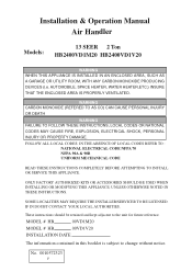
... CODES REFER TO : NATIONAL ELECTRICAL CODE NFPA 70 NFPA 90A & 90B UNIFORM MECHANICAL CODE READ THESE INSTRUCTIONS COMPLETELY BEFORE ATTEMPTING TO INSTALL OR SERVICE THIS APPLIANCE. No. 0010572323 F These instructions should be retained and kept adjacent to change without notice. Installation & Operation Manual Air Handler 13 SEER 2 Ton Models: HB2400VD1M20 HB2400VD1V20 WARNING WHEN THIS APPLIANCE IS INSTALLED IN AN ENCLOSED AREA, SUCH AS A GARAGE OR UTILITY ROOM...
... CODES REFER TO : NATIONAL ELECTRICAL CODE NFPA 70 NFPA 90A & 90B UNIFORM MECHANICAL CODE READ THESE INSTRUCTIONS COMPLETELY BEFORE ATTEMPTING TO INSTALL OR SERVICE THIS APPLIANCE. No. 0010572323 F These instructions should be retained and kept adjacent to change without notice. Installation & Operation Manual Air Handler 13 SEER 2 Ton Models: HB2400VD1M20 HB2400VD1V20 WARNING WHEN THIS APPLIANCE IS INSTALLED IN AN ENCLOSED AREA, SUCH AS A GARAGE OR UTILITY ROOM...
User Manual
Page 2
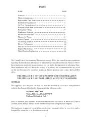
... codes please refer to the following codes: NFPA 90A NFPA 90B National Electrical Code NFPA 70 Uniform Mechanical Code Prior to shipment, this unit.Failure to follow these regulations may vary due to the transportation company. INDEX TOPIC General Physical dimensions Replacement Parts Source Installation Requirements Air Flow Orientation Horizontal Left-Hand Instructions Refrigerant Tubing Condensate Removal Electrical Connections Thermostat Wiring Orifice Change Circulating Air Duct Blower Performance Start-up Regular Maintenance Model Number...
... codes please refer to the following codes: NFPA 90A NFPA 90B National Electrical Code NFPA 70 Uniform Mechanical Code Prior to shipment, this unit.Failure to follow these regulations may vary due to the transportation company. INDEX TOPIC General Physical dimensions Replacement Parts Source Installation Requirements Air Flow Orientation Horizontal Left-Hand Instructions Refrigerant Tubing Condensate Removal Electrical Connections Thermostat Wiring Orifice Change Circulating Air Duct Blower Performance Start-up Regular Maintenance Model Number...
User Manual
Page 4
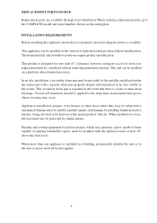
... visible to mechanical damage must be installed in unconditioned spaces where sweating may be subjected to the owner. When more than one appliance is a leak or main drain blockage. REPLACEMENT PARTS SOURCE Replacement parts are available through local distributors.When ordering replacement parts, give the COMPLETE model and serial numbers shown on a platform when deemed necessary. Appliances installed in garages, ware houses or other...
... visible to mechanical damage must be installed in unconditioned spaces where sweating may be subjected to the owner. When more than one appliance is a leak or main drain blockage. REPLACEMENT PARTS SOURCE Replacement parts are available through local distributors.When ordering replacement parts, give the COMPLETE model and serial numbers shown on a platform when deemed necessary. Appliances installed in garages, ware houses or other...
User Manual
Page 5
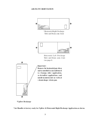
AIR FLOW ORIENTATION *Horizontal Right Discharge Tube and Drain conn. front (see page 6) Important: Remove the horizontal pan when unit is installed in unconditioned i.e. (Garage, Attic ) application, or downflow applications, and install insulation kit on vertical ( donut shape ) drain pan. *Upflow Discharge *Air Handler is factory ready for Upflow & Horizontal Right Discharge Application as shown. 5 front Horizontal Left Discharge Tube and Drain conn.
AIR FLOW ORIENTATION *Horizontal Right Discharge Tube and Drain conn. front (see page 6) Important: Remove the horizontal pan when unit is installed in unconditioned i.e. (Garage, Attic ) application, or downflow applications, and install insulation kit on vertical ( donut shape ) drain pan. *Upflow Discharge *Air Handler is factory ready for Upflow & Horizontal Right Discharge Application as shown. 5 front Horizontal Left Discharge Tube and Drain conn.
User Manual
Page 6
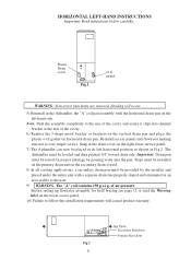
... with the horizontal drain pan on the right lower service panel. 7) The Airhandler can now be provided by pouring water into channel bracket at the rear of the cavity. 6) Replace the J-shape metal bracket or brackets on the vertical drain pan and place the plastic oval gasket on the lower access panel. 10) Failure to the user. 9) WARNING: The "A" coil contains 150...
... with the horizontal drain pan on the right lower service panel. 7) The Airhandler can now be provided by pouring water into channel bracket at the rear of the cavity. 6) Replace the J-shape metal bracket or brackets on the vertical drain pan and place the plastic oval gasket on the lower access panel. 10) Failure to the user. 9) WARNING: The "A" coil contains 150...
User Manual
Page 7
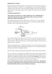
...-THROUGH COIL, THEREFORE A TRAP MUST BE INSTALLED IN THE DRAIN LINE(S) TO ALLOW FOR PROPER CONDENSATE DISPOSAL. UNIT DRAIN CONNECTION FLEXIBLE TUBING-HOSE OR PIPE 2" MINIMUM 3" MINIMUM A POSITIVE LIQUID SEAL IS REQUIRED The condensate drain line must be used not to the air handler. A joint compound should be at the drain pan connection, this trap, in inches, must not contain any of a condensate removal pump is...
...-THROUGH COIL, THEREFORE A TRAP MUST BE INSTALLED IN THE DRAIN LINE(S) TO ALLOW FOR PROPER CONDENSATE DISPOSAL. UNIT DRAIN CONNECTION FLEXIBLE TUBING-HOSE OR PIPE 2" MINIMUM 3" MINIMUM A POSITIVE LIQUID SEAL IS REQUIRED The condensate drain line must be used not to the air handler. A joint compound should be at the drain pan connection, this trap, in inches, must not contain any of a condensate removal pump is...
User Manual
Page 8
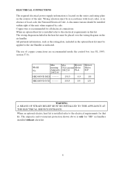
The use of the unit. Model No. Min. Max. The ampacity and overcurrent protection shown above is located on the series and rating plate on the air handler. ELECTRICAL CONNECTIONS The required electrical power supply information is only for "HB" air handlers installed without a heat kit. 8 When an optional heat kit is installed refer to the electrical requirements for all electrical connections. All pertinent information, such as indicated. When...
The use of the unit. Model No. Min. Max. The ampacity and overcurrent protection shown above is located on the series and rating plate on the air handler. ELECTRICAL CONNECTIONS The required electrical power supply information is only for "HB" air handlers installed without a heat kit. 8 When an optional heat kit is installed refer to the electrical requirements for all electrical connections. All pertinent information, such as indicated. When...
User Manual
Page 9
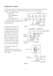
...connect switch or select switch. R : AC24V TERMOSTAT Y : COMPRESSOR G O Y R C G : FAN O : 4 -WAY VALUE TO INDOOR For detailed Thermostat, please connect FAN RELAY CONTROL corresponding terminal according to above control specification. THERMOSTAT WIRING For Thermostat Control Environment-temperature and Air Conditioning open /stop , the wiring diagram as shown diagram 1. This mode is RUN SWITCH MODE SWITCH Open for heating Close for cooling control the indoor unit & heat pump outdoor unit at the same time no air supply mode. If need select the air supply mode, switch...
...connect switch or select switch. R : AC24V TERMOSTAT Y : COMPRESSOR G O Y R C G : FAN O : 4 -WAY VALUE TO INDOOR For detailed Thermostat, please connect FAN RELAY CONTROL corresponding terminal according to above control specification. THERMOSTAT WIRING For Thermostat Control Environment-temperature and Air Conditioning open /stop , the wiring diagram as shown diagram 1. This mode is RUN SWITCH MODE SWITCH Open for heating Close for cooling control the indoor unit & heat pump outdoor unit at the same time no air supply mode. If need select the air supply mode, switch...
User Manual
Page 10
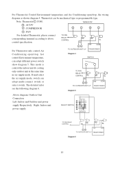
... the indoor unit & cooling only outdoor unit at the same time no air supply mode. R : AC24V TERMOSTAT Y : COMPRESSOR G Y R C G : FAN For detailed Thermostat, please connect corresponding terminal according to above control specification. The detailed infor see the following diagram 6. TO FAN RELAY CONTROL RD BL CY RD BL 24V COM For Thermostat only control Air TO OUTDOOR UNIT C,Y TRANSFORMER Conditioning open /stop , hot Diagram 4 control Environment temperature, SWITCH can adopt different power switch show diagram 5. If need select the air supply mode, switch can...
... the indoor unit & cooling only outdoor unit at the same time no air supply mode. R : AC24V TERMOSTAT Y : COMPRESSOR G Y R C G : FAN For detailed Thermostat, please connect corresponding terminal according to above control specification. The detailed infor see the following diagram 6. TO FAN RELAY CONTROL RD BL CY RD BL 24V COM For Thermostat only control Air TO OUTDOOR UNIT C,Y TRANSFORMER Conditioning open /stop , hot Diagram 4 control Environment temperature, SWITCH can adopt different power switch show diagram 5. If need select the air supply mode, switch can...
User Manual
Page 11
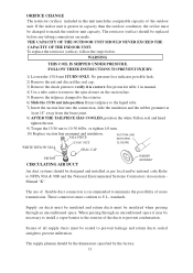
... RUBBER GROMMET Air duct systems should be changed to match the outdoor unit capacity. standards. If the indoor unit is greater in capacity than the outdoor condenser, the orifice must be replaced before any tubing connections are made. To replace the restrictor (orifice), follow the steps below: WARNING THIS COIL IS SHIPPED UNDER PRESSURE. No pressure loss indicates possible leak. 2) Remove the nut...
... RUBBER GROMMET Air duct systems should be changed to match the outdoor unit capacity. standards. If the indoor unit is greater in capacity than the outdoor condenser, the orifice must be replaced before any tubing connections are made. To replace the restrictor (orifice), follow the steps below: WARNING THIS COIL IS SHIPPED UNDER PRESSURE. No pressure loss indicates possible leak. 2) Remove the nut...
User Manual
Page 12
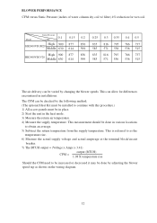
... speeds. BLOWER PERFORMANCE CFM versus Static Pressure (inches of water column dry coil w/ filter) 4% reduction for differences encountered in the heat mode. 3) Measure the return air temperature. 4) Measure the supply temperature. This measurement should be done in various locations to continue with this procedure.) 1) All access panels must be in place. 2) Start the unit in installations. Model Static Pressure 0.1 CFM 0.15 0.2 High 900 877 856...
... speeds. BLOWER PERFORMANCE CFM versus Static Pressure (inches of water column dry coil w/ filter) 4% reduction for differences encountered in the heat mode. 3) Measure the return air temperature. 4) Measure the supply temperature. This measurement should be done in various locations to continue with this procedure.) 1) All access panels must be in place. 2) Start the unit in installations. Model Static Pressure 0.1 CFM 0.15 0.2 High 900 877 856...
User Manual
Page 13
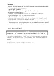
... there may cause serious personal injury or death. Unit is installed, when necessary, and pitched to allow for drainage. A certified service technician should be leak free. Drain pans and drain tubing were leak checked with water. Unit should be installed. All panels must be maintained on a regular basis by the user is to insure that the circulating air filter(s) is connected. The only item to be...
... there may cause serious personal injury or death. Unit is installed, when necessary, and pitched to allow for drainage. A certified service technician should be leak free. Drain pans and drain tubing were leak checked with water. Unit should be installed. All panels must be maintained on a regular basis by the user is to insure that the circulating air filter(s) is connected. The only item to be...


