
User Manual
Page 2
... Source Installation Requirements Air Flow Orientation Horizontal Left-Hand Instructions Downflow Instructions Refrigerant Tubing Condensate Removal Electrical Connections Thermostat Wiring Orifice Change Circulating Air Duct Blower Performance Start-up Regular Maintenance Model Number Explanation PAGE 2 3 4 4 5 6 7 8 8 9 10 12 12 13 14 14 15 The United States Environmental Protection Agency (EPA) has issued...
... Source Installation Requirements Air Flow Orientation Horizontal Left-Hand Instructions Downflow Instructions Refrigerant Tubing Condensate Removal Electrical Connections Thermostat Wiring Orifice Change Circulating Air Duct Blower Performance Start-up Regular Maintenance Model Number Explanation PAGE 2 3 4 4 5 6 7 8 8 9 10 12 12 13 14 14 15 The United States Environmental Protection Agency (EPA) has issued...
User Manual
Page 7
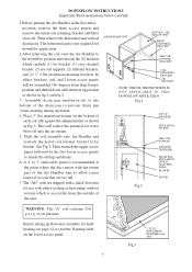
... NOT APPLICABLE IN THIS DOWNFLOW APPLICATION Fig.1 Fig.2 TOP OF WRAPPER INSULATION JACKET ZEE COIL SUPPORT WRAPPER STIFFENER DRAIN PAN INSULATION DPI KIT (HATCHED AREA) BLOWER MOTOR WARNING: The "A" coil contains 150 p.s.i.g. DOWNFLOW INSTRUCTIONS Important: Read instructions below carefully 1.Before putting the Air Handler in the downflow position, remove the three...
... NOT APPLICABLE IN THIS DOWNFLOW APPLICATION Fig.1 Fig.2 TOP OF WRAPPER INSULATION JACKET ZEE COIL SUPPORT WRAPPER STIFFENER DRAIN PAN INSULATION DPI KIT (HATCHED AREA) BLOWER MOTOR WARNING: The "A" coil contains 150 p.s.i.g. DOWNFLOW INSTRUCTIONS Important: Read instructions below carefully 1.Before putting the Air Handler in the downflow position, remove the three...

User Manual
Page 9
The use of the unit, when required by code. Max. Min. Blower running Over-current Motor Ampacity 208/230 FLA 208/230 HB2400VC1M20 -------- 15/15 0.9 Blower Motor H.P. 1/8 WARNING A MEANS OF STRAIN RELIEF MUST BE INSTALLED TO THIS APPLIANCE AT THE ELECTRICAL ... heat kit is located on the series and rating plate on the air handler. Model No. Blower Ampacity Over-current Motor 208/230 208/230 FLA HB2400VA1M20 -------- 15/15 0.9 Blower Motor H.P. 1/8 HB3000VA1M20 -------- 15/15 2.3 1/3 HB3600VA1M20 -------- 15/15 2.3 1/3 Model No. Max. The ampacity and...
The use of the unit, when required by code. Max. Min. Blower running Over-current Motor Ampacity 208/230 FLA 208/230 HB2400VC1M20 -------- 15/15 0.9 Blower Motor H.P. 1/8 WARNING A MEANS OF STRAIN RELIEF MUST BE INSTALLED TO THIS APPLIANCE AT THE ELECTRICAL ... heat kit is located on the series and rating plate on the air handler. Model No. Blower Ampacity Over-current Motor 208/230 208/230 FLA HB2400VA1M20 -------- 15/15 0.9 Blower Motor H.P. 1/8 HB3000VA1M20 -------- 15/15 2.3 1/3 HB3600VA1M20 -------- 15/15 2.3 1/3 Model No. Max. The ampacity and...

User Manual
Page 13
...to obtain an average. 5) Subtract the return temperature from the supply temperature. Model Static Pressure 0.1 CFM HB2400VA1M20 High 900 Middle 630 HB3000VA1M20 High HB3600VA1M20 Middle 0.15 877 614 1016 1276 1016 0.2 856 599 990 1244 990 0.25 835 585 965 1213 965 0.3 0....41) output (BTUH) CFM = 1.08 X temperature rise Should the CFM need to be increased or decreased it may be done in installations. BLOWER PERFORMANCE CFM versus Static Pressure (inches of water column dry coil w/ filter) 4% reduction for differences encountered in various locations to continue with this...
...to obtain an average. 5) Subtract the return temperature from the supply temperature. Model Static Pressure 0.1 CFM HB2400VA1M20 High 900 Middle 630 HB3000VA1M20 High HB3600VA1M20 Middle 0.15 877 614 1016 1276 1016 0.2 856 599 990 1244 990 0.25 835 585 965 1213 965 0.3 0....41) output (BTUH) CFM = 1.08 X temperature rise Should the CFM need to be increased or decreased it may be done in installations. BLOWER PERFORMANCE CFM versus Static Pressure (inches of water column dry coil w/ filter) 4% reduction for differences encountered in various locations to continue with this...


