
User Manual
Page 3
... to a waste collecting center and used again after adequate recycling. Unplug the air conditioner in the User's Guide. All these valuable materials may be done by professional people, don't install unit by insisting on an appropriate, anti-pollution method of disposal. Safety Instructions and Warnings Before starting the air conditioner, read the information given in a air conditioner can be put into smaller pieces...
... to a waste collecting center and used again after adequate recycling. Unplug the air conditioner in the User's Guide. All these valuable materials may be done by professional people, don't install unit by insisting on an appropriate, anti-pollution method of disposal. Safety Instructions and Warnings Before starting the air conditioner, read the information given in a air conditioner can be put into smaller pieces...

User Manual
Page 4
... unplug your air conditioner by pulling on the outdoor unit. If the refrigerant spurts out and gets into the inlet/outlet and swing louver. In no case should be applied in the PC board to unplug the air conditioner before opening inlet grill. CAUTIONS For the purpose of safety, the air conditioner must be allowed to sit on the power cord. D All electrical repairs must be...
... unplug your air conditioner by pulling on the outdoor unit. If the refrigerant spurts out and gets into the inlet/outlet and swing louver. In no case should be applied in the PC board to unplug the air conditioner before opening inlet grill. CAUTIONS For the purpose of safety, the air conditioner must be allowed to sit on the power cord. D All electrical repairs must be...
User Manual
Page 5
... WARNING! Use copper wire only. DANGER! Always consult authorized service personnel for lengthy periods in the direct cooling airflow. Do not start and stop operation immediately, turn off power source when not using the unit for extended periods. Do not climb on place objects on . Do not operate the air conditioner with air filters installed. Turn off the circuit breaker, and consult authorized service personnel. Do not drink the water drained from the indoor unit. Do...
... WARNING! Use copper wire only. DANGER! Always consult authorized service personnel for lengthy periods in the direct cooling airflow. Do not start and stop operation immediately, turn off power source when not using the unit for extended periods. Do not climb on place objects on . Do not operate the air conditioner with air filters installed. Turn off the circuit breaker, and consult authorized service personnel. Do not drink the water drained from the indoor unit. Do...

User Manual
Page 6
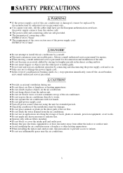
... FILTER The AIR FILTER has been treated to resist mildew growth, thus allowing cleaner use and easier care. 4 HEAT & COOL TYPE When the SLEEP button is reached, the unit automatically turns off . HEAT & COOL TYPE Merely press the ON/OFF button, and the unit will begin automatic operation in any of the Heating, Cooling and Blow modes as appropriate, in accordance with the thermostat setting and the actual temperature of the room. WIRELESS REMOTE CONTROL UNIT The WIRELESS REMOTE CONTROL UNIT...
... FILTER The AIR FILTER has been treated to resist mildew growth, thus allowing cleaner use and easier care. 4 HEAT & COOL TYPE When the SLEEP button is reached, the unit automatically turns off . HEAT & COOL TYPE Merely press the ON/OFF button, and the unit will begin automatic operation in any of the Heating, Cooling and Blow modes as appropriate, in accordance with the thermostat setting and the actual temperature of the room. WIRELESS REMOTE CONTROL UNIT The WIRELESS REMOTE CONTROL UNIT...

User Manual
Page 7
NAME OF PARTS 10 11 Fig.1 Fig.2 13 1 POWER 4 OPER 5 TIMER 6 COMP 7 3 EMER 2 Fig.2 3 9 8 Fig.1 Indoor Unit 1 Operating Control Panel (Fig.2) 2 Emergency switch 3 Remote Control Signal Receiver 4 Power Indicator Lamp (Red) 5 OPERATION Indicator Lamp (Green) 6 TIMER Indicator Lamp (Yellow) 7 Compressor Run Lamp (Green) 8 Intake Grill (Fig.3) 9 Air Filter 10 UP/DOWN Air Direction Flaps 11 RIGHT/LEFT Air Direction Louvers (behind UP/DOWN Air Direction Flaps) 12 Fig.2 Outdoor Unit 12 Intake grill 13 Outlet grill 14 Pipe Unit 14 5
NAME OF PARTS 10 11 Fig.1 Fig.2 13 1 POWER 4 OPER 5 TIMER 6 COMP 7 3 EMER 2 Fig.2 3 9 8 Fig.1 Indoor Unit 1 Operating Control Panel (Fig.2) 2 Emergency switch 3 Remote Control Signal Receiver 4 Power Indicator Lamp (Red) 5 OPERATION Indicator Lamp (Green) 6 TIMER Indicator Lamp (Yellow) 7 Compressor Run Lamp (Green) 8 Intake Grill (Fig.3) 9 Air Filter 10 UP/DOWN Air Direction Flaps 11 RIGHT/LEFT Air Direction Louvers (behind UP/DOWN Air Direction Flaps) 12 Fig.2 Outdoor Unit 12 Intake grill 13 Outlet grill 14 Pipe Unit 14 5

User Manual
Page 8
... Grill. Cleaning the Air Filter Open the Intake Grill 1. Push in a solution of the Intake Grill. (figure 2) Air Filter About 30 mm Arm Intake Grill Side Panel Hook Notch Arm (Figure 1) Filter bracket (Figure 2) 2. If dirt is installed securely. When removing and replacing the air filters, be pushed down so that their top edges fit under the projections at the top of mild detergent and warm water. Clean the Air Filters. Air Filter Handle Bracket...
... Grill. Cleaning the Air Filter Open the Intake Grill 1. Push in a solution of the Intake Grill. (figure 2) Air Filter About 30 mm Arm Intake Grill Side Panel Hook Notch Arm (Figure 1) Filter bracket (Figure 2) 2. If dirt is installed securely. When removing and replacing the air filters, be pushed down so that their top edges fit under the projections at the top of mild detergent and warm water. Clean the Air Filters. Air Filter Handle Bracket...

User Manual
Page 9
... noise may be changed in the system. During operation, white fog or steam comes out from accumulating on the outdoor unit is removed. (during defrosting operation) In heating operation, indoor fan won 't resume cooling, dry or heating operation in dry operation. Won't start? TROUBLE SHOOTING Followings are not problems Sound of water flowing is stopped, this will switch to blowing operation. Please wait 3 minutes Unit will go on the furniture. No outlet air or fan speed can't be heard. During unit operation...
... noise may be changed in the system. During operation, white fog or steam comes out from accumulating on the outdoor unit is removed. (during defrosting operation) In heating operation, indoor fan won 't resume cooling, dry or heating operation in dry operation. Won't start? TROUBLE SHOOTING Followings are not problems Sound of water flowing is stopped, this will switch to blowing operation. Please wait 3 minutes Unit will go on the furniture. No outlet air or fan speed can't be heard. During unit operation...

User Manual
Page 10
...? This is very dangerous, please disconnect power supply immediately and contact your dealer. Any doors or windows left open? TROUBLE SHOOTING Before ask for services, please first check your unit against the following problems occur, please stop it immediately and contact your dealer. Is leakage current breaker activated? Power supply switch is heard. 8 Cold air blows out (in heating mode) Is air conditioner in standby condition in the room? Water comes out in cooling/dry operation.
...? This is very dangerous, please disconnect power supply immediately and contact your dealer. Any doors or windows left open? TROUBLE SHOOTING Before ask for services, please first check your unit against the following problems occur, please stop it immediately and contact your dealer. Is leakage current breaker activated? Power supply switch is heard. 8 Cold air blows out (in heating mode) Is air conditioner in standby condition in the room? Water comes out in cooling/dry operation.
User Manual
Page 11
... temperature than those listed above, the heat-exchanger may form on the heat-pump principle, absorbing heat from outdoor air and transferring that heat indoors. Also, during Cooling and Dry modes, if the unit is used under conditions of rooms in conjunction with a Microcomputer-controlled Automatic Defrosting function. The wiring method should be disposed properly. If you use this unit is heated. If frost forms, the air conditioner will temporarily stop, and the defrosting circuit will flash...
... temperature than those listed above, the heat-exchanger may form on the heat-pump principle, absorbing heat from outdoor air and transferring that heat indoors. Also, during Cooling and Dry modes, if the unit is used under conditions of rooms in conjunction with a Microcomputer-controlled Automatic Defrosting function. The wiring method should be disposed properly. If you use this unit is heated. If frost forms, the air conditioner will temporarily stop, and the defrosting circuit will flash...

User Manual
Page 12
... Nylon fastener Drain hose Non-adhesive tape VT wire 1 For fixing the drain hose 1 1 For fixing the drain 1 hose L 280mm Pipe hole cover 1 Remote controller Use for air conditioner 1 operation Wall hole cover 1 Battery 2 For remote controller unit Main pipes Connecting cables Cushion Drain-elbow Wall bracket 1 1 4 Only for the heat pump 1 type 2 Mark A B C D E F G H Optional parts Parts name Adhesive tape Saddle (L.S) with screws Connecting electric cable for indoor and outdoor Drain hose Heat insulation material Piping hole cover Putty Plastic clamp 10 Use them as...
... Nylon fastener Drain hose Non-adhesive tape VT wire 1 For fixing the drain hose 1 1 For fixing the drain 1 hose L 280mm Pipe hole cover 1 Remote controller Use for air conditioner 1 operation Wall hole cover 1 Battery 2 For remote controller unit Main pipes Connecting cables Cushion Drain-elbow Wall bracket 1 1 4 Only for the heat pump 1 type 2 Mark A B C D E F G H Optional parts Parts name Adhesive tape Saddle (L.S) with screws Connecting electric cable for indoor and outdoor Drain hose Heat insulation material Piping hole cover Putty Plastic clamp 10 Use them as...

User Manual
Page 13
... able to blow all over the room. (3) Install the unit near an electric outlet or special branch circuit. (4) Do not install the unit where it will not topple or fall. Left CAUTION (1)Do not install where there is easy. (6) Install the unit where the drain pipe can be easily installed. (7) Take servicing, etc. Left Right 30 cm or more 1.5m 30 cm or more Outdoor unit 9.52mm...
... able to blow all over the room. (3) Install the unit near an electric outlet or special branch circuit. (4) Do not install the unit where it will not topple or fall. Left CAUTION (1)Do not install where there is easy. (6) Install the unit where the drain pipe can be easily installed. (7) Take servicing, etc. Left Right 30 cm or more 1.5m 30 cm or more Outdoor unit 9.52mm...

User Manual
Page 14
... the indoor unit is easy. (4) During heating operation, drain water flows from the air conditioner do not disturb neighbors. (8) Provide the space shown in Fig.B so that the air flow is not blocked. Therefore, install the outdoor unit in the path of the warm air. (6) Take the weight of the four directions front, rear, and both sides. Also for efficient operation, leave open three of the air conditioner...
... the indoor unit is easy. (4) During heating operation, drain water flows from the air conditioner do not disturb neighbors. (8) Provide the space shown in Fig.B so that the air flow is not blocked. Therefore, install the outdoor unit in the path of the warm air. (6) Take the weight of the four directions front, rear, and both sides. Also for efficient operation, leave open three of the air conditioner...

User Manual
Page 15
....4) Wall 7cm Indoor unit 6mm outdoor unit The drain hose can be wired before the indoor unit is tilted downward toward the outdoor for smooth water flow. REMOVE THE INTAKE GRILL Open the intake grill and remove the three or four or six screws.(Fig. 1) Fig. 1 Machine screw Tapping screw Tapping screw Intake grill Remark: The main unit can be made in Fig.5,and mount the set to wall, install the accessory wall bracket at...
....4) Wall 7cm Indoor unit 6mm outdoor unit The drain hose can be wired before the indoor unit is tilted downward toward the outdoor for smooth water flow. REMOVE THE INTAKE GRILL Open the intake grill and remove the three or four or six screws.(Fig. 1) Fig. 1 Machine screw Tapping screw Tapping screw Intake grill Remark: The main unit can be made in Fig.5,and mount the set to wall, install the accessory wall bracket at...

User Manual
Page 16
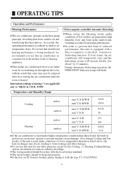
... secure the drain hose with a nylon fastener. (Fig.6) (Fig. 6) Drain pan Drain hose Nylon fastener Wrap the insulation (drain hose) around the drain hose connection. (Fig.7) (Fig. 7) Drain pan Drain hose Insulation (Drain hose) Be sure to arrange the drain hose correctly so that it is too high. Fig. 8 OK NO NO Arrange the drain hose lower than this portion. Installation procedures 2. UNDER CEILING TYPE Using the installation template, drill holes for piping and...
... secure the drain hose with a nylon fastener. (Fig.6) (Fig. 6) Drain pan Drain hose Nylon fastener Wrap the insulation (drain hose) around the drain hose connection. (Fig.7) (Fig. 7) Drain pan Drain hose Insulation (Drain hose) Be sure to arrange the drain hose correctly so that it is too high. Fig. 8 OK NO NO Arrange the drain hose lower than this portion. Installation procedures 2. UNDER CEILING TYPE Using the installation template, drill holes for piping and...
User Manual
Page 17
INSTALLING INDOOR UNIT Reset the hex bolts as shown in the direction.) 3. DRILLING FOR PIPING Select piping and drain directions. (Fig.11) Rear (Install the drain hose in Fig.16. Fig. 14 15 Bracket (Left) Bracket (Right) When the directions are selected, drill 80mm and 50mm or 150mm dia. DRILLING HOLES FOR ANCHOR BOLTS AND INSTALLING THE ANCHOR BOLTS With a concrete drill, drill four 12.7 mm dia. it...
INSTALLING INDOOR UNIT Reset the hex bolts as shown in the direction.) 3. DRILLING FOR PIPING Select piping and drain directions. (Fig.11) Rear (Install the drain hose in Fig.16. Fig. 14 15 Bracket (Left) Bracket (Right) When the directions are selected, drill 80mm and 50mm or 150mm dia. DRILLING HOLES FOR ANCHOR BOLTS AND INSTALLING THE ANCHOR BOLTS With a concrete drill, drill four 12.7 mm dia. it...

User Manual
Page 18
... L L dimension Liquid pipe 1.6 to 1.8mm(6.35mm dia) Gas pipe 2.2 to 2.4mm(15.88mm dia) Gas pipe 3.4 to 2.6mm(19.05mm) Liquid pipe 1.8 to collapse them. Fig. 21 Pass the drain hose through here Cut the grill VT wire Drain hose OK NO Extend the pipe by your hands. Arrange the drain hose lower than the drain hose connecting port of the indoor unit.(Fig.18) Fig. 18 Remove the hole cover...
... L L dimension Liquid pipe 1.6 to 1.8mm(6.35mm dia) Gas pipe 2.2 to 2.4mm(15.88mm dia) Gas pipe 3.4 to 2.6mm(19.05mm) Liquid pipe 1.8 to collapse them. Fig. 21 Pass the drain hose through here Cut the grill VT wire Drain hose OK NO Extend the pipe by your hands. Arrange the drain hose lower than the drain hose connecting port of the indoor unit.(Fig.18) Fig. 18 Remove the hole cover...

User Manual
Page 19
... or more of piping Flare connection Gas pipe 3-way valve Indoor unit Outdoor unit Liquid pipe 3-way valve Flare connection (3) Limitations for one way piping length and vertical height difference. Refrigerant piping (1) Outline of overhead space is needed for refrigerant piping Do not twist or crush piping. Check flare-connected area for gas leakage. (2) Piping size Liquid pipe Gas pipe 9.52x0.8mm 15.88x1.0mm Install the removed flare nuts...
... or more of piping Flare connection Gas pipe 3-way valve Indoor unit Outdoor unit Liquid pipe 3-way valve Flare connection (3) Limitations for one way piping length and vertical height difference. Refrigerant piping (1) Outline of overhead space is needed for refrigerant piping Do not twist or crush piping. Check flare-connected area for gas leakage. (2) Piping size Liquid pipe Gas pipe 9.52x0.8mm 15.88x1.0mm Install the removed flare nuts...
User Manual
Page 20
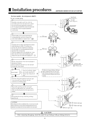
... make flaring work again and vacuumize, fill up prescribed refrigerant from the service port, open 3-way valve and 3-way. If the scale-moves back in gaugemanifold and stop gas leakage, discharge whole refrigerants from the serice port. CAUTION: If the refrigerant of the air conditioner leaks, it does not stop the operation of the vacuum pump. Installation procedures AIRPURGINGMETHOD(TOUSEVACUUMPUMP) For these models , the refrigerant is...
... make flaring work again and vacuumize, fill up prescribed refrigerant from the service port, open 3-way valve and 3-way. If the scale-moves back in gaugemanifold and stop gas leakage, discharge whole refrigerants from the serice port. CAUTION: If the refrigerant of the air conditioner leaks, it does not stop the operation of the vacuum pump. Installation procedures AIRPURGINGMETHOD(TOUSEVACUUMPUMP) For these models , the refrigerant is...

User Manual
Page 22
... cord with the cord clamp.(If the insulator is chafed, electric leakage may cause burning of the electric parts. (2) Connect the connection cords firmly to power supply Installation procedures ELECTRICAL REQUIREMENT Electric wire size and fuse capacity: Table 5 Connection MAX 3.5 3.5 cord (mm2) MIN 2.5 2.5 Fuse capacity(A) 20 30 ELECTRICAL WIRING CAUTION (1) Match the terminal block numbers and connection cord colors with those of the connection cord with the screw. INDOOR UNIT SIDE (1) Remove the electric...
... cord with the cord clamp.(If the insulator is chafed, electric leakage may cause burning of the electric parts. (2) Connect the connection cords firmly to power supply Installation procedures ELECTRICAL REQUIREMENT Electric wire size and fuse capacity: Table 5 Connection MAX 3.5 3.5 cord (mm2) MIN 2.5 2.5 Fuse capacity(A) 20 30 ELECTRICAL WIRING CAUTION (1) Match the terminal block numbers and connection cord colors with those of the connection cord with the screw. INDOOR UNIT SIDE (1) Remove the electric...

User Manual
Page 23
... breaker in accordance with the operating manual: (1) Starting and stopping method, operation switching, temperature adjustment, timer, air flow switching, and other electrical appliances. CUSTOMER GUIDANCE Explain the following to the customer in accordance with the related laws and regulations and electric company standards. (2) Air filter removal and cleaning, and how to use air louvers. (3) Give the operating and installation manuals to the capacity of the room air conditioner. (3) The circuit breaker is on the remote control unit normal? (2) Does each pole. (4) Perform wiring work...
... breaker in accordance with the operating manual: (1) Starting and stopping method, operation switching, temperature adjustment, timer, air flow switching, and other electrical appliances. CUSTOMER GUIDANCE Explain the following to the customer in accordance with the related laws and regulations and electric company standards. (2) Air filter removal and cleaning, and how to use air louvers. (3) Give the operating and installation manuals to the capacity of the room air conditioner. (3) The circuit breaker is on the remote control unit normal? (2) Does each pole. (4) Perform wiring work...


