User Manual
Page 2
...injury. SAFETy Table of contents Safety 3 Specifications 6 Setup 6 Operation 9 Maintenance 11 Parts Lists and Diagrams 13 Warranty 16 WARNING SyMBOLS AND DEFINITIONS This is used to alert... you to potential personal injury hazards. Indicates a hazardous situation which , if not avoided, will result in minor or moderate injury. SETUp OpERATION MAINTENANcE Page 2 For technical questions, please call 1-888-866-5797. Addresses practices not related to avoid possible injury or death. Item 43389...
...injury. SAFETy Table of contents Safety 3 Specifications 6 Setup 6 Operation 9 Maintenance 11 Parts Lists and Diagrams 13 Warranty 16 WARNING SyMBOLS AND DEFINITIONS This is used to alert... you to potential personal injury hazards. Indicates a hazardous situation which , if not avoided, will result in minor or moderate injury. SETUp OpERATION MAINTENANcE Page 2 For technical questions, please call 1-888-866-5797. Addresses practices not related to avoid possible injury or death. Item 43389...
User Manual
Page 3
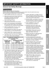
... moving parts, binding of moving parts. DISCONNECT TOOLS before turning it was designed. 8. when changing accessories, such as blades, bits, cutters, and the like. 16. USE PROPER EXTENSION CORD. Make sure your extension cord is in . WEAR PROPER APPAREL. CHECK DAMAGED PARTS. check for best and safest performance. DIRECTION OF FEED. Item 43389 For technical questions, please call 1-888-866-5797. REMOVE ADJUSTING KEYS AND WRENCHES. KEEP WORK AREA...
... moving parts, binding of moving parts. DISCONNECT TOOLS before turning it was designed. 8. when changing accessories, such as blades, bits, cutters, and the like. 16. USE PROPER EXTENSION CORD. Make sure your extension cord is in . WEAR PROPER APPAREL. CHECK DAMAGED PARTS. check for best and safest performance. DIRECTION OF FEED. Item 43389 For technical questions, please call 1-888-866-5797. REMOVE ADJUSTING KEYS AND WRENCHES. KEEP WORK AREA...
User Manual
Page 4
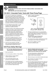
... for drill accessory and workpiece material. 5. Only use only identical replacement parts. 9. Do not depress the spindle lock when starting or during operation. 10. This tool is properly installed and grounded in a risk of accessories or attachments not recommended by an appropriate standards agency. Wear eye protection. 2. Repair or replace damaged or worn cord immediately. Do not wear gloves, necktie, or loose clothing. 3. Item 43389 MAINTENANcE Grounding Instructions SAFETy SETUp OpERATION...
... for drill accessory and workpiece material. 5. Only use only identical replacement parts. 9. Do not depress the spindle lock when starting or during operation. 10. This tool is properly installed and grounded in a risk of accessories or attachments not recommended by an appropriate standards agency. Wear eye protection. 2. Repair or replace damaged or worn cord immediately. Do not wear gloves, necktie, or loose clothing. 3. Item 43389 MAINTENANcE Grounding Instructions SAFETy SETUp OpERATION...
User Manual
Page 5
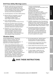
... not being caused or worsened from these chemicals: work . SAFETy SETUp Drill press Safety Warnings (cont.) 11. Stay alert, watch what you do the work . 5. Do not use . WARNING: Some dust created by the operator. To reduce your exposure to these exposures varies, depending on the tool. 15. WARNING: Handling the cord on the tool. SAVE THESE INSTRUcTIONS. Maintain labels and nameplates on this product...
... not being caused or worsened from these chemicals: work . SAFETy SETUp Drill press Safety Warnings (cont.) 11. Stay alert, watch what you do the work . 5. Do not use . WARNING: Some dust created by the operator. To reduce your exposure to these exposures varies, depending on the tool. 15. WARNING: Handling the cord on the tool. SAVE THESE INSTRUcTIONS. Maintain labels and nameplates on this product...
User Manual
Page 6
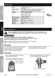
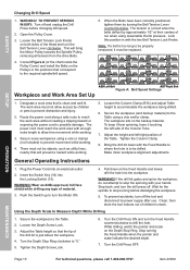
... assembly, bolt the Base to a supporting structure before drilling or driving screws. Verify that installation surface has no hidden utility lines before use of the Table Support (B17). Column Tube (B14) Hex Screws (B12) 3. TO pREVENT SERIOUS INJURy FROM AccIDENTAL OpERATION: Turn the power Switch of the tool off and unplug the tool from its electrical outlet before set up or use . Install the column clamp (B16) on the Base, aligning the mounting holes. 2. OpERATION MAINTENANcE...
... assembly, bolt the Base to a supporting structure before drilling or driving screws. Verify that installation surface has no hidden utility lines before use of the Table Support (B17). Column Tube (B14) Hex Screws (B12) 3. TO pREVENT SERIOUS INJURy FROM AccIDENTAL OpERATION: Turn the power Switch of the tool off and unplug the tool from its electrical outlet before set up or use . Install the column clamp (B16) on the Base, aligning the mounting holes. 2. OpERATION MAINTENANcE...
User Manual
Page 7
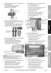
... wrench. Hand tighten. Slide the Motor Pulley onto the Motor shaft. Lay a straight edge across the two pulleys. Head Assembly Belt Tension Handle (3) Motor Adjusting Knob (1) Set Screws (2) Hex Screw (38) Washer (39) Hex Nut (42) Motor (43) Column Tube 10. Install the Motor pulley (A11). Hold Motor in two Set Screws (2), into place. 7. Mount the Table crank (B4) onto the right side of four Hex Screws (38) b. e. Tighten the Motor Pulley onto the shaft using the Allen wrench and Set Screw (A10). c. Item 43389...
... wrench. Hand tighten. Slide the Motor Pulley onto the Motor shaft. Lay a straight edge across the two pulleys. Head Assembly Belt Tension Handle (3) Motor Adjusting Knob (1) Set Screws (2) Hex Screw (38) Washer (39) Hex Nut (42) Motor (43) Column Tube 10. Install the Motor pulley (A11). Hold Motor in two Set Screws (2), into place. 7. Mount the Table crank (B4) onto the right side of four Hex Screws (38) b. e. Tighten the Motor Pulley onto the shaft using the Allen wrench and Set Screw (A10). c. Item 43389...

User Manual
Page 8
... start. Place the long side of the white wire to protect the Chuck nose. If the Table is square (90º) to the bit, loosen Set Screw (B1) with the Allen wrench and the Hex Screw (B8) with the Hex Wrench (B20). e. Secure a three inches drill bit in or out). SAFETy SETUp 12. Turn the Motor Adjusting Knob (1) clockwise to raise the Table so that the Table is not square to the Head Assembly and drill bit. Insert...
... start. Place the long side of the white wire to protect the Chuck nose. If the Table is square (90º) to the bit, loosen Set Screw (B1) with the Allen wrench and the Hex Screw (B8) with the Hex Wrench (B20). e. Secure a three inches drill bit in or out). SAFETy SETUp 12. Turn the Motor Adjusting Knob (1) clockwise to raise the Table so that the Table is not square to the Head Assembly and drill bit. Insert...
User Manual
Page 9
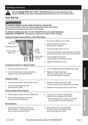
... Hex Screw, then the Set Screw. 1. Depth Stop 5. Tilting the Table 3. Loosen the Depth Screw Lock. 2. Ensure that the jaws do not touch the flutes of the workpiece. Loosen the Depth Screw Lock (6). 4. Turn the Feed Handle counterclockwise to bring the tip of the drill bit down, next to the desired angle. Setting the Depth Scale to Drill to the Oil Bottle (52). 2. Add the desired cutting oil to a Specified Depth Locking Switch (15) Switch Key (18) Rocker (light) Switch (17) 1. SAFETy SETUp Operating Instructions...
... Hex Screw, then the Set Screw. 1. Depth Stop 5. Tilting the Table 3. Loosen the Depth Screw Lock. 2. Ensure that the jaws do not touch the flutes of the workpiece. Loosen the Depth Screw Lock (6). 4. Turn the Feed Handle counterclockwise to bring the tip of the drill bit down, next to the desired angle. Setting the Depth Scale to Drill to the Oil Bottle (52). 2. Add the desired cutting oil to a Specified Depth Locking Switch (15) Switch Key (18) Rocker (light) Switch (17) 1. SAFETy SETUp Operating Instructions...
User Manual
Page 10
... stop turning before changing drill speed. 2. Route the power cord along a safe route to drill the hole. Secure loose workpieces using a vise and/or clamp. Adjust the height and left side of the Table. General Operating Instructions 1. Plug the Power Cord into the Locking Switch (15). Push the Switch up to turn the Feed Handle counterclockwise to reach the work area with the two Belt Tension Lock Knobs. To prevent accidents, turn the Belt Tension Lever clockwise. While drilling...
... stop turning before changing drill speed. 2. Route the power cord along a safe route to drill the hole. Secure loose workpieces using a vise and/or clamp. Adjust the height and left side of the Table. General Operating Instructions 1. Plug the Power Cord into the Locking Switch (15). Push the Switch up to turn the Feed Handle counterclockwise to reach the work area with the two Belt Tension Lock Knobs. To prevent accidents, turn the Belt Tension Lever clockwise. While drilling...
User Manual
Page 11
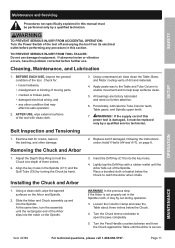
... surfaces clean. 5. Turn the Chuck sleeve clockwise to hold the Chuck at a depth of the tool with a rubber mallet until the Arbor is damaged, it must be replaced only by a qualified service technician. Using compressed air, blow clean the Table, Base, and Motor cooling vents of the tool. Slide the Arbor and Chuck assembly up and into the key holes. 4. AFTER USE, wipe external surfaces of three inches. 2. Adjust the Depth Stop Ring to...
... surfaces clean. 5. Turn the Chuck sleeve clockwise to hold the Chuck at a depth of the tool with a rubber mallet until the Arbor is damaged, it must be replaced only by a qualified service technician. Using compressed air, blow clean the Table, Base, and Motor cooling vents of the tool. Slide the Arbor and Chuck assembly up and into the key holes. 4. AFTER USE, wipe external surfaces of three inches. 2. Adjust the Depth Stop Ring to...
User Manual
Page 12
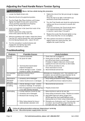
... needed , use one with the proper diameter for example.) Tool operates Extension cord too long or slowly. or too tight (bearing damage). Blocked motor housing vents. 3. Loosen the Depth Screw Lock. 2. Insert a screwdriver in place. 7. Replace the (outer) Hex Nut and tighten on tool. 4. Tool's thermal reset breaker tripped (if equipped). 3. Press reset button on top of the Spring Cap (26). Carbon brushes worn or damaged. If an extension cord is too tight, it stops. SAFETy SETUp Adjusting...
... needed , use one with the proper diameter for example.) Tool operates Extension cord too long or slowly. or too tight (bearing damage). Blocked motor housing vents. 3. Loosen the Depth Screw Lock. 2. Insert a screwdriver in place. 7. Replace the (outer) Hex Nut and tighten on tool. 4. Tool's thermal reset breaker tripped (if equipped). 3. Press reset button on top of the Spring Cap (26). Carbon brushes worn or damaged. If an extension cord is too tight, it stops. SAFETy SETUp Adjusting...
User Manual
Page 13
... 49 50 51 52 53 54 Description LED Lamp Hex Wrench, L, M5 Hex Wrench, L, M3 Wire Tie Power Cord w/ Plug Wire Connector Cord Clamp Support Motor Bracket Bolt, M8x1.25-20 Washer, 8x16x1.6 Motor Mount Motor Cord Nut, M8x1.25 Motor Nut, M12x1.75 Lock Washer, 1/2 Motor Bracket Support Screw, M8x1.25-16 Adjusting Lever Pan Head Screw, M5x0.8-12 Oiler Bracket Screw, 5mm x 8mm Oil Bottle Spigot Assembly Tubing 29a SETUp OpERATION MAINTENANcE Item 43389 For technical questions, please call 1-888-866-5797.
... 49 50 51 52 53 54 Description LED Lamp Hex Wrench, L, M5 Hex Wrench, L, M3 Wire Tie Power Cord w/ Plug Wire Connector Cord Clamp Support Motor Bracket Bolt, M8x1.25-20 Washer, 8x16x1.6 Motor Mount Motor Cord Nut, M8x1.25 Motor Nut, M12x1.75 Lock Washer, 1/2 Motor Bracket Support Screw, M8x1.25-16 Adjusting Lever Pan Head Screw, M5x0.8-12 Oiler Bracket Screw, 5mm x 8mm Oil Bottle Spigot Assembly Tubing 29a SETUp OpERATION MAINTENANcE Item 43389 For technical questions, please call 1-888-866-5797.

User Manual
Page 14
... Nut Spindle Pulley Pulley Insert Pulley Guard Roundhead Washer Screw, M6x1.0-12 Set Screw, M10x1.5-12 part A11 A12 A13 A14 A15 A16 A17 A18 A19 Description Motor Pulley Knob Panhead Screw, M5x0.8-12 Idler Pivot Center Pulley Ball Bearing, 15mm V-Belt, 1/2x27 Foam Washer Lockwasher, Ext., M6 SETUp OpERATION MAINTENANcE pLEASE READ THE FOLLOWING cAREFULLy THE MANUFACTURER AND/OR DISTRIBUTOR HAS PROVIDED THE PARTS LIST AND ASSEMBLY DIAGRAM IN THIS MANUAL...
... Nut Spindle Pulley Pulley Insert Pulley Guard Roundhead Washer Screw, M6x1.0-12 Set Screw, M10x1.5-12 part A11 A12 A13 A14 A15 A16 A17 A18 A19 Description Motor Pulley Knob Panhead Screw, M5x0.8-12 Idler Pivot Center Pulley Ball Bearing, 15mm V-Belt, 1/2x27 Foam Washer Lockwasher, Ext., M6 SETUp OpERATION MAINTENANcE pLEASE READ THE FOLLOWING cAREFULLy THE MANUFACTURER AND/OR DISTRIBUTOR HAS PROVIDED THE PARTS LIST AND ASSEMBLY DIAGRAM IN THIS MANUAL...
User Manual
Page 15
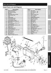
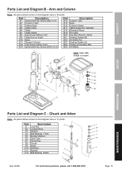
... (A) Hollow Connecting Bolt Oil Bottle Note: Table (B6) design is suqare. 21 22 23 24 25 SETUp OpERATION MAINTENANcE parts List and Diagram c - Arm and column Note: All part numbers shown in this diagram have a "C" prefix part C1 C2 C3 C4 C5 C6 C7 C8 C9 C10 C11 C12 Description Lock Nut Locking Ring Washer Ball Bearing, 17mm Rubber Washer Quill Tube Chuck Key Chuck Arbor Drift Key Spindle Ball Bearing, 25mm Item...
... (A) Hollow Connecting Bolt Oil Bottle Note: Table (B6) design is suqare. 21 22 23 24 25 SETUp OpERATION MAINTENANcE parts List and Diagram c - Arm and column Note: All part numbers shown in this diagram have a "C" prefix part C1 C2 C3 C4 C5 C6 C7 C8 C9 C10 C11 C12 Description Lock Nut Locking Ring Washer Ball Bearing, 17mm Rubber Washer Quill Tube Chuck Key Chuck Arbor Drift Key Spindle Ball Bearing, 25mm Item...
User Manual
Page 16
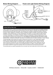
... is free from defects in no defect, or that the defect resulted from state to the original purchaser that its products meet high quality and durability standards, and warrants to state. 3491 Mission Oaks Blvd. • pO Box 6009 • camarillo, cA 93011 • 1-888-866-5797 Motor Wiring Diagram power and Light Switch Wiring Diagram Limited 90 Day Warranty Harbor Freight Tools...
... is free from defects in no defect, or that the defect resulted from state to the original purchaser that its products meet high quality and durability standards, and warrants to state. 3491 Mission Oaks Blvd. • pO Box 6009 • camarillo, cA 93011 • 1-888-866-5797 Motor Wiring Diagram power and Light Switch Wiring Diagram Limited 90 Day Warranty Harbor Freight Tools...


