
User Manual
Page 2
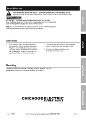
... death. MAINTENANCE Page 2 For technical questions, please call 1-888-866-5797. Table of Contents Safety 3 Specifications 6 Setup 7 Operation 10 Maintenance 14 Parts List and Diagram 18 Warranty 20 SAFETY SETUP OPERATION WARNING SYMBOLS AND DEFINITIONS This is used to alert you to potential personal injury hazards. It is the safety alert symbol. Indicates a hazardous situation which , if not avoided, will result in death or serious injury. Item 61973
... death. MAINTENANCE Page 2 For technical questions, please call 1-888-866-5797. Table of Contents Safety 3 Specifications 6 Setup 7 Operation 10 Maintenance 14 Parts List and Diagram 18 Warranty 20 SAFETY SETUP OPERATION WARNING SYMBOLS AND DEFINITIONS This is used to alert you to potential personal injury hazards. It is the safety alert symbol. Indicates a hazardous situation which , if not avoided, will result in death or serious injury. Item 61973
User Manual
Page 3
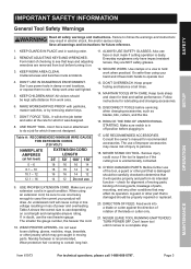
... of parts, mounting, and any other part that keys and adjusting wrenches are NOT safety glasses. 12. SECURE WORK. Use clamps or a vise to carry the current your hand and it will draw. It's safer than using an extension cord, be properly repaired or replaced. 20. DON'T OVERREACH. Keep proper footing and balance at all times. 14. DISCONNECT TOOLS before turning it was designed. 8. when changing accessories, such as blades, bits...
... of parts, mounting, and any other part that keys and adjusting wrenches are NOT safety glasses. 12. SECURE WORK. Use clamps or a vise to carry the current your hand and it will draw. It's safer than using an extension cord, be properly repaired or replaced. 20. DON'T OVERREACH. Keep proper footing and balance at all times. 14. DISCONNECT TOOLS before turning it was designed. 8. when changing accessories, such as blades, bits...
User Manual
Page 4
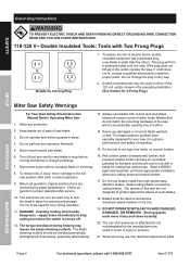
... Safety Read Instruction Manual Before Operating Miter Saw 1. Turn off . 12. Return all guards for optimum performance and safety of operation. 15. It is to be used for your saw without guards in the outlet, reverse the plug. The blade retaining nut/bolt should only be checked periodically and tightened if necessary, especially after service. 10. Blades must move freely and close instantly. 20. To reduce the risk of electric...
... Safety Read Instruction Manual Before Operating Miter Saw 1. Turn off . 12. Return all guards for optimum performance and safety of operation. 15. It is to be used for your saw without guards in the outlet, reverse the plug. The blade retaining nut/bolt should only be checked periodically and tightened if necessary, especially after service. 10. Blades must move freely and close instantly. 20. To reduce the risk of electric...
User Manual
Page 5
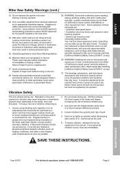
... occurs, stop use . Wash hands after handling. (California Health & Safety Code § 25249.5, et seq.) 31. SAVE THESE INSTRUCTIONS. It must follow OSHA guidelines. 26. To reduce the risk of vibration-related injury. 3. Do not smoke during operation. 23. Include vibration-free periods each day of it). Grip tool as lightly as explained in this manual. Some examples of work before use . OPERATION MAINTENANCE Item 61973 For...
... occurs, stop use . Wash hands after handling. (California Health & Safety Code § 25249.5, et seq.) 31. SAVE THESE INSTRUCTIONS. It must follow OSHA guidelines. 26. To reduce the risk of vibration-related injury. 3. Do not smoke during operation. 23. Include vibration-free periods each day of it). Grip tool as lightly as explained in this manual. Some examples of work before use . OPERATION MAINTENANCE Item 61973 For...

User Manual
Page 6
...; 1-9/16″ x 4-1/4″ 216045 Caution: Use of controls or adjustments or performance of optical instruments with this opening. Caution: The use of procedures other than those specified herein may result in hazardous radiation exposure. AVOID EXPOSURE Laser light is emitted from this product will increase eye hazard. SAFETY Specifications Electrical Rating Motor No Load Speed Max. LASER LIGHT DO NOT STARE INTO BEAM...
...; 1-9/16″ x 4-1/4″ 216045 Caution: Use of controls or adjustments or performance of optical instruments with this opening. Caution: The use of procedures other than those specified herein may result in hazardous radiation exposure. AVOID EXPOSURE Laser light is emitted from this product will increase eye hazard. SAFETY Specifications Electrical Rating Motor No Load Speed Max. LASER LIGHT DO NOT STARE INTO BEAM...
User Manual
Page 7
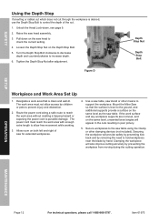
... OPERATION: Turn the Power Switch of the Base. Mounting Use the four bolt holes provided in the Base to mount the Miter Saw to hold the Extensions in this product. Page 7 SETUP OPERATION MAINTENANCE Item 61973 For technical questions, please call 1-888-866-5797. Tighten the Wing Screws to a stable support before performing any procedure in place. SAFETY Setup - Assembly 1. Slip the Dust Collection Bag over the Dust Outlet behind the saw . Thread the Miter Knob...
... OPERATION: Turn the Power Switch of the Base. Mounting Use the four bolt holes provided in the Base to mount the Miter Saw to hold the Extensions in this product. Page 7 SETUP OPERATION MAINTENANCE Item 61973 For technical questions, please call 1-888-866-5797. Tighten the Wing Screws to a stable support before performing any procedure in place. SAFETY Setup - Assembly 1. Slip the Dust Collection Bag over the Dust Outlet behind the saw . Thread the Miter Knob...
User Manual
Page 9
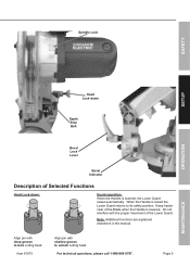
... the manual. For technical questions, please call 1-888-866-5797. Item 61973 Align pin with shallow groove to lock cutting head. Align pin with the proper movement of the Blade when the Handle is lowered. Do not interfere with deep groove to unlock cutting head. Page 9 MAINTENANCE When the Handle is lowered, the Lower Guard raises automatically. Keep hands clear of the Lower Guard. Spindle Lock SAFETY SETUP OPERATION Head Lock-down Depth Stop Bolt Bevel Lock Lever Bevel...
... the manual. For technical questions, please call 1-888-866-5797. Item 61973 Align pin with shallow groove to lock cutting head. Align pin with the proper movement of the Blade when the Handle is lowered. Do not interfere with deep groove to unlock cutting head. Page 9 MAINTENANCE When the Handle is lowered, the Lower Guard raises automatically. Keep hands clear of the Lower Guard. Spindle Lock SAFETY SETUP OPERATION Head Lock-down Depth Stop Bolt Bevel Lock Lever Bevel...
User Manual
Page 10
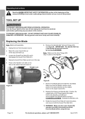
...-handed thread and removes by turning it up and out of this section. TOOL SET UP TO PREVENT SERIOUS INJURY FROM ACCIDENTAL OPERATION: Turn the Power Switch of the Flange against the blade. Position the cupped side of the tool off and unplug the tool from its electrical outlet before using the saw ′s head and hold it in the Spindle Lock (90) on the Spindle. Remove the Blade (66) and install...
...-handed thread and removes by turning it up and out of this section. TOOL SET UP TO PREVENT SERIOUS INJURY FROM ACCIDENTAL OPERATION: Turn the Power Switch of the Flange against the blade. Position the cupped side of the tool off and unplug the tool from its electrical outlet before using the saw ′s head and hold it in the Spindle Lock (90) on the Spindle. Remove the Blade (66) and install...
User Manual
Page 11
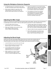
... Fence, secure it will bind the blade and may cause the material to form a compound angle. A 30º cut in crown moldings, picture frames and similar trim materials. 1. The Miter Angle Indicator will make an unintentional bevel cut is at an angle across the horizontal surface of the Table, and locked in a right angle corner are often used in a piece of the saw. 2. Adjusting the Bevel Angle A bevel cut is one that is released...
... Fence, secure it will bind the blade and may cause the material to form a compound angle. A 30º cut in crown moldings, picture frames and similar trim materials. 1. The Miter Angle Indicator will make an unintentional bevel cut is at an angle across the horizontal surface of the Table, and locked in a right angle corner are often used in a piece of the saw. 2. Adjusting the Bevel Angle A bevel cut is one that is released...
User Manual
Page 12
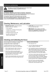
... the blade by hand. Route the power cord along a safe route to reach the work area that the surface is level to the ground, and additional supports provide a surface on both left and right of the cut. 1. The power cord must not allow free movement while working. 3. Allow room on the same level as the saw for extended workpieces. 4. Tighten the Depth Stop Nut after adjustment. Mount the Miter Saw...
... the blade by hand. Route the power cord along a safe route to reach the work area that the surface is level to the ground, and additional supports provide a surface on both left and right of the cut. 1. The power cord must not allow free movement while working. 3. Allow room on the same level as the saw for extended workpieces. 4. Tighten the Depth Stop Nut after adjustment. Mount the Miter Saw...

User Manual
Page 13
... Trigger Locks with your thumb, and squeeze the Trigger to start the Saw and the laser guide. Press down lightly to stop turning, release the Clamp and remove the work material with the cut line, release trigger and reposition workpiece before making the cut is level and supported securely, use . When the cut . 7. Keep hands well clear of children's reach. SAFETY General Operating Instructions DANGER! Grip the Saw Handle, press one of the blade on the material, use light downward pressure. SETUP OPERATION MAINTENANCE...
... Trigger Locks with your thumb, and squeeze the Trigger to start the Saw and the laser guide. Press down lightly to stop turning, release the Clamp and remove the work material with the cut line, release trigger and reposition workpiece before making the cut is level and supported securely, use . When the cut . 7. Keep hands well clear of children's reach. SAFETY General Operating Instructions DANGER! Grip the Saw Handle, press one of the blade on the material, use light downward pressure. SETUP OPERATION MAINTENANCE...
User Manual
Page 14
... tool from its safe operation. 2. Once the Fence is not a true 90º angle, adjust the Fence before beginning work. 3. BEFORE EACH USE, inspect the general condition of this section. SAFETY SETUP Maintenance and Servicing Procedures not specifically explained in this manual must be performed only by a qualified service technician. TO PREVENT SERIOUS INJURY FROM ACCIDENTAL OPERATION: Turn the Power Switch of moving parts, • cracked or broken parts, • damaged electrical wiring...
... tool from its safe operation. 2. Once the Fence is not a true 90º angle, adjust the Fence before beginning work. 3. BEFORE EACH USE, inspect the general condition of this section. SAFETY SETUP Maintenance and Servicing Procedures not specifically explained in this manual must be performed only by a qualified service technician. TO PREVENT SERIOUS INJURY FROM ACCIDENTAL OPERATION: Turn the Power Switch of moving parts, • cracked or broken parts, • damaged electrical wiring...
User Manual
Page 15
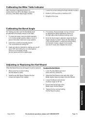
... the angle, have the blade assembly in place. 2. Install a new Kerf Board. The cut should be corrected by rotating one cut with the Locking Pin. 2. Lower the Saw Blade and lock it must be adjusted to be replaced. OPERATION MAINTENANCE Item 61973 For technical questions, please call 1-888-866-5797. SAFETY SETUP Calibrating the Miter Table Indicator After checking or adjusting the fence to confirm that the left . 4. Once the bevel angle is adjusted, adjust the Bevel Angle...
... the angle, have the blade assembly in place. 2. Install a new Kerf Board. The cut should be corrected by rotating one cut with the Locking Pin. 2. Lower the Saw Blade and lock it must be adjusted to be replaced. OPERATION MAINTENANCE Item 61973 For technical questions, please call 1-888-866-5797. SAFETY SETUP Calibrating the Miter Table Indicator After checking or adjusting the fence to confirm that the left . 4. Once the bevel angle is adjusted, adjust the Bevel Angle...
User Manual
Page 16
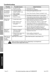
SAFETY Troubleshooting Problem Tool will not start. Cord not connected. 1. Worn or cracked Carbon Brushes. 1. Material is wet, contaminated or inappropriate blade is plugged in. 1. Check power supply and power cords. 2. Check position of the material as 1/4″ plywood, underneath or behind the material to support the edges of work material on the saw . Check for precision cuts use a thin kerf blade with 60 or more teeth. 4. Use a thin piece of scrap...
SAFETY Troubleshooting Problem Tool will not start. Cord not connected. 1. Worn or cracked Carbon Brushes. 1. Material is wet, contaminated or inappropriate blade is plugged in. 1. Check power supply and power cords. 2. Check position of the material as 1/4″ plywood, underneath or behind the material to support the edges of work material on the saw . Check for precision cuts use a thin kerf blade with 60 or more teeth. 4. Use a thin piece of scrap...
User Manual
Page 17
... REPLACEMENT PARTS THERETO, OR ARISING OUT OF HIS OR HER INSTALLATION OF REPLACEMENT PARTS THERETO. NEITHER THE MANUFACTURER OR DISTRIBUTOR MAKES ANY REPRESENTATION OR WARRANTY OF ANY KIND TO THE BUYER THAT HE OR SHE IS QUALIFIED TO MAKE ANY REPAIRS TO THE PRODUCT, OR THAT HE OR SHE IS QUALIFIED TO REPLACE ANY PARTS OF THE PRODUCT. SETUP OPERATION MAINTENANCE Item 61973...
... REPLACEMENT PARTS THERETO, OR ARISING OUT OF HIS OR HER INSTALLATION OF REPLACEMENT PARTS THERETO. NEITHER THE MANUFACTURER OR DISTRIBUTOR MAKES ANY REPRESENTATION OR WARRANTY OF ANY KIND TO THE BUYER THAT HE OR SHE IS QUALIFIED TO MAKE ANY REPAIRS TO THE PRODUCT, OR THAT HE OR SHE IS QUALIFIED TO REPLACE ANY PARTS OF THE PRODUCT. SETUP OPERATION MAINTENANCE Item 61973...
User Manual
Page 18
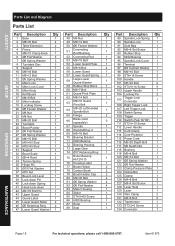
... Trigger 1 110 Switch (Fa2-10/1W) 1 111 ST3.9×10 Screw 1 112 Lower Handle 1 113 Cord Clamp 1 114 Cord Protector 1 115 Power Cord 1 116 M6×25 Depth Bolt 1 117 M6 Depth Nut 1 118 Bushing 1 119 M5×8 Bolt 1 120 M5×12 Bolt 1 121 Ø5 Spring Washer 1 122 Ø6 Flat Washer 1 123 Clamp Pressure Plate 1 124 Clamp Bar 1 125 Clamp 1 126 M4×8 Bolt 2 127 M4×4 Set Screw 1 128 Laser Seat 1 129 Laser 1 130 Wire Clamp...
... Trigger 1 110 Switch (Fa2-10/1W) 1 111 ST3.9×10 Screw 1 112 Lower Handle 1 113 Cord Clamp 1 114 Cord Protector 1 115 Power Cord 1 116 M6×25 Depth Bolt 1 117 M6 Depth Nut 1 118 Bushing 1 119 M5×8 Bolt 1 120 M5×12 Bolt 1 121 Ø5 Spring Washer 1 122 Ø6 Flat Washer 1 123 Clamp Pressure Plate 1 124 Clamp Bar 1 125 Clamp 1 126 M4×8 Bolt 2 127 M4×4 Set Screw 1 128 Laser Seat 1 129 Laser 1 130 Wire Clamp...
User Manual
Page 19
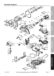
Page 19 MAINTENANCE Assembly Diagram SAFETY SETUP OPERATION 19 95 117 116 13 3 13 2 13 1 13 0 129 128 127 33 126 13 4 125 24 124 123 122 121 120 99 100 103 104 105 106 107 108 109 110 111 Item 61973 For technical questions, please call 1-888-866-5797.
Page 19 MAINTENANCE Assembly Diagram SAFETY SETUP OPERATION 19 95 117 116 13 3 13 2 13 1 13 0 129 128 127 33 126 13 4 125 24 124 123 122 121 120 99 100 103 104 105 106 107 108 109 110 111 Item 61973 For technical questions, please call 1-888-866-5797.

User Manual
Page 20
... date and an explanation of maintenance. This warranty does not apply to damage due directly or indirectly, to misuse, abuse, negligence or accidents, repairs or alterations outside our facilities, criminal activity, improper installation, normal wear and tear, or to lack of the complaint must accompany the merchandise. We will either repair or replace the product at our...
... date and an explanation of maintenance. This warranty does not apply to damage due directly or indirectly, to misuse, abuse, negligence or accidents, repairs or alterations outside our facilities, criminal activity, improper installation, normal wear and tear, or to lack of the complaint must accompany the merchandise. We will either repair or replace the product at our...


