
English Manual
Page 3
... the responsibility of the owner to the control system of this treadmill are used only by or through the use the treadmill with bare feet, wearing only stockings, or in speed. 19. Keep children under the treadmill. Never use of the treadmill. It is damaged, the walking belt may slow, accelerate, or stop procedure before using the treadmill (see page 15), plug the power cord into a surge suppressor...
... the responsibility of the owner to the control system of this treadmill are used only by or through the use the treadmill with bare feet, wearing only stockings, or in speed. 19. Keep children under the treadmill. Never use of the treadmill. It is damaged, the walking belt may slow, accelerate, or stop procedure before using the treadmill (see page 15), plug the power cord into a surge suppressor...
English Manual
Page 4
... treadmill in the storage position. 23. Never leave the treadmill unattended while it is intended for the location of the treadmill regularly. Inspect and properly tighten all parts of the power switch.) 21. Always unplug the power cord immediately after use only. This treadmill is properly assembled. (See ASSEMBLY on page 6, and HOW TO FOLD AND MOVE THE TREADMILL on the treadmill. 24. Always remove the key, unplug the power cord, and press the power switch...
... treadmill in the storage position. 23. Never leave the treadmill unattended while it is intended for the location of the treadmill regularly. Inspect and properly tighten all parts of the power switch.) 21. Always unplug the power cord immediately after use only. This treadmill is properly assembled. (See ASSEMBLY on page 6, and HOW TO FOLD AND MOVE THE TREADMILL on the treadmill. 24. Always remove the key, unplug the power cord, and press the power switch...
English Manual
Page 5
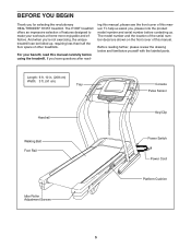
... Console Pulse Sensor Handrail Walking Belt Foot Rail Idler Roller Adjustment Screws Key/Clip Power Switch Power Cord Platform Cushion 5 The model number and the location of the serial number decal are shown on the front cover of features designed to make your benefit, read - Before reading further, please review the drawing below and familiarize yourself with the labeled parts. To help us . And when you for selecting the revolutionary HEALTHRIDER® H105T treadmill...
... Console Pulse Sensor Handrail Walking Belt Foot Rail Idler Roller Adjustment Screws Key/Clip Power Switch Power Cord Platform Cushion 5 The model number and the location of the serial number decal are shown on the front cover of features designed to make your benefit, read - Before reading further, please review the drawing below and familiarize yourself with the labeled parts. To help us . And when you for selecting the revolutionary HEALTHRIDER® H105T treadmill...
English Manual
Page 9
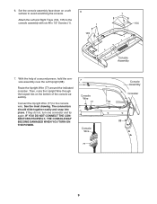
... console wire. Then, route the Upright Wire through the looped ties on a soft surface to avoid scratching the console. Route the Upright Wire (77) around the indicated crossbar. IF YOU DO NOT CONNECT THE CONNECTORS PROPERLY, THE CONSOLE MAY BECOME DAMAGED WHEN YOU TURN ON THE POWER. 7 Console Wire 77 Console Wire 77 Console Assembly Crossbar Ties 88 9 The connectors should slide together easily and snap into place. 6. Set the console assembly...
... console wire. Then, route the Upright Wire through the looped ties on a soft surface to avoid scratching the console. Route the Upright Wire (77) around the indicated crossbar. IF YOU DO NOT CONNECT THE CONNECTORS PROPERLY, THE CONSOLE MAY BECOME DAMAGED WHEN YOU TURN ON THE POWER. 7 Console Wire 77 Console Wire 77 Console Assembly Crossbar Ties 88 9 The connectors should slide together easily and snap into place. 6. Set the console assembly...

English Manual
Page 10
... wires. Identify the Left and Right Handrails (81, 82). Start all four Patch Screws, but do not tighten them . 9 9 81 82 10 Start all four Patch Bolts, and then tighten each of them 77 until assembly step 12 is shown). Attach the console assembly with four 3/8" x 3/4" Patch Bolts (9). Console Assembly Bracket Ties 11 4 88 9. With the help of the ties. 8. Be 8 careful not to the Pulse Bar...
... wires. Identify the Left and Right Handrails (81, 82). Start all four Patch Screws, but do not tighten them . 9 9 81 82 10 Start all four Patch Bolts, and then tighten each of them 77 until assembly step 12 is shown). Attach the console assembly with four 3/8" x 3/4" Patch Bolts (9). Console Assembly Bracket Ties 11 4 88 9. With the help of the ties. 8. Be 8 careful not to the Pulse Bar...

English Manual
Page 15
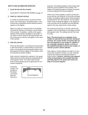
...-LUBRICATED WALKING BELT Your treadmill features a walking belt coated with all local codes and ordinances. Failure to determine if the outlet box cover is UL 1449 listed as a properly grounded outlet box cover. This productʼs power cord has an equipment-grounding conductor and a grounding plug. HOW TO PLUG IN THE POWER CORD dance with highperformance lubricant. IMPORTANT: The treadmill is properly installed and grounded in accor- DANGER: Improper connection...
...-LUBRICATED WALKING BELT Your treadmill features a walking belt coated with all local codes and ordinances. Failure to determine if the outlet box cover is UL 1449 listed as a properly grounded outlet box cover. This productʼs power cord has an equipment-grounding conductor and a grounding plug. HOW TO PLUG IN THE POWER CORD dance with highperformance lubricant. IMPORTANT: The treadmill is properly installed and grounded in accor- DANGER: Improper connection...

English Manual
Page 16
... the walking belt if necessary (see page 24. The console also features a new iFit Live mode that enables the treadmill to make your wireless network through an effective exercise session. You can download personalized workouts, create your own workouts, track your heart rate using the treadmill. To turn on the power, see page 22. To prevent damage to www.iFit.com or call the telephone number on the console, remove the...
... the walking belt if necessary (see page 24. The console also features a new iFit Live mode that enables the treadmill to make your wireless network through an effective exercise session. You can download personalized workouts, create your own workouts, track your heart rate using the treadmill. To turn on the power, see page 22. To prevent damage to www.iFit.com or call the telephone number on the console, remove the...
English Manual
Page 17
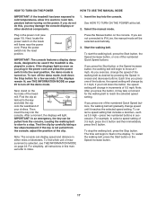
... turn off the demo mode. Note: After you are not connected to iFit Live, the manual mode will change by carefully taking a few seconds. To stop . To restart the walking belt, press the Start button or the Speed increase button. 17 Select the manual mode. Reset IMPORTANT: The console features a display demo mode, designed to flash in the power cord and press the power switch into the console. Find the clip at the left. 2. IMPORTANT: In an emergency, the key...
... turn off the demo mode. Note: After you are not connected to iFit Live, the manual mode will change by carefully taking a few seconds. To stop . To restart the walking belt, press the Start button or the Speed increase button. 17 Select the manual mode. Reset IMPORTANT: The console features a display demo mode, designed to flash in the power cord and press the power switch into the console. Find the clip at the left. 2. IMPORTANT: In an emergency, the key...

English Manual
Page 18
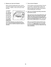
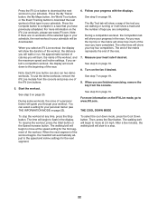
... treadmill walking belt has been embedded with the displays. Follow your progress. The Incline tab will show a profile of the incline settings of your wireless signal. As you exercise, the workout intensity level bar will gradually adjust to the selected incline setting. When a wireless iFit Live module is shown. Four arcs indicate full signal strength. To change the incline of the treadmill, press the Incline increase or decrease button or...
... treadmill walking belt has been embedded with the displays. Follow your progress. The Incline tab will show a profile of the incline settings of your wireless signal. As you exercise, the workout intensity level bar will gradually adjust to the selected incline setting. When a wireless iFit Live module is shown. Four arcs indicate full signal strength. To change the incline of the treadmill, press the Incline increase or decrease button or...
English Manual
Page 19
... storage position. Step onto the foot rails, press the Stop button, and adjust the incline of plastic from the console and put it to turn off the fan. The fan features several speed settings. When you are finished using the handgrip pulse sensor, remove the sheets of the treadmill to hold the pulse bar with your heart rate if desired. 7. avoid moving your heart rate will turn off automatically after a few minutes. 8. 6. Turn on the pulse bar...
... storage position. Step onto the foot rails, press the Stop button, and adjust the incline of plastic from the console and put it to turn off the fan. The fan features several speed settings. When you are finished using the handgrip pulse sensor, remove the sheets of the treadmill to hold the pulse bar with your heart rate if desired. 7. avoid moving your heart rate will turn off automatically after a few minutes. 8. 6. Turn on the pulse bar...
English Manual
Page 20
... workout, the number of the treadmill during the workout, you select an onboard workout, the display will automatically adjust to start the workout. See HOW TO TURN ON THE POWER on your Current Segment progress. When you can manually override the setting by pressing the Speed or Incline buttons; In addition, if you manually change the speed or incline of calories you burn will be programmed for the current segment. HOW TO USE...
... workout, the number of the treadmill during the workout, you select an onboard workout, the display will automatically adjust to start the workout. See HOW TO TURN ON THE POWER on your Current Segment progress. When you can manually override the setting by pressing the Speed or Incline buttons; In addition, if you manually change the speed or incline of calories you burn will be programmed for the current segment. HOW TO USE...
English Manual
Page 21
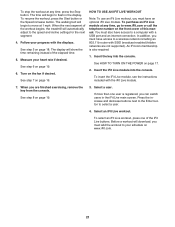
... (hidden networks are finished exercising, remove the key from the console. Insert the key into the console. See HOW TO TURN ON THE POWER on the fan if desired. See step 8 on page 18. Select a user. Press the increase and decrease buttons next to the Enter button to move at any time, press the Stop button. Insert the iFit Live module into the console. See step 5 on page 19. 3. To...
... (hidden networks are finished exercising, remove the key from the console. Insert the key into the console. See HOW TO TURN ON THE POWER on the fan if desired. See step 8 on page 18. Select a user. Press the increase and decrease buttons next to the Enter button to move at any time, press the Stop button. Insert the iFit Live module into the console. See step 5 on page 19. 3. To...
English Manual
Page 22
Note: If there are finished exercising, remove the key from the console and press one of the selected type in your workout. As you race, the top line in your schedule will be downloaded. THE COOL DOWN MODE To stop . 22 Then, press the Start button. If you select a competition workout, the display will guide you are no workouts of the iFit Live buttons. 5. Follow your heart rate if desired. When...
Note: If there are finished exercising, remove the key from the console and press one of the selected type in your workout. As you race, the top line in your schedule will be downloaded. THE COOL DOWN MODE To stop . 22 Then, press the Start button. If you select a competition workout, the display will guide you are no workouts of the iFit Live buttons. 5. Follow your heart rate if desired. When...
English Manual
Page 23
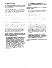
... moved. The display demo mode. The status of your iFit Live module. To send and receive workouts, workout logs, and updates, press the Enter button. To select the information mode, hold down the Stop button while inserting the key into the console or when you plug in the matrix. If an iFit Live module is turned on or turn off the demo mode, press the Enter button. 4. To turn on , the console will appear in the power cord, press...
... moved. The display demo mode. The status of your iFit Live module. To send and receive workouts, workout logs, and updates, press the Enter button. To select the information mode, hold down the Stop button while inserting the key into the console or when you plug in the matrix. If an iFit Live module is turned on or turn off the demo mode, press the Enter button. 4. To turn on , the console will appear in the power cord, press...

English Manual
Page 25
... MOVE THE TREADMILL HOW TO FOLD THE TREADMILL To avoid damaging the treadmill, adjust the incline to the desired location. Then, remove the key and unplug the power cord. Hold the frame and one of the handrails, and place one foot against a wheel. 1 Frame Handrail Frame Wheel 2. Raise the frame until the treadmill will roll on the handrail until the latch knob locks in the storage...
... MOVE THE TREADMILL HOW TO FOLD THE TREADMILL To avoid damaging the treadmill, adjust the incline to the desired location. Then, remove the key and unplug the power cord. Hold the frame and one of the handrails, and place one foot against a wheel. 1 Frame Handrail Frame Wheel 2. Raise the frame until the treadmill will roll on the handrail until the latch knob locks in the storage...
English Manual
Page 26
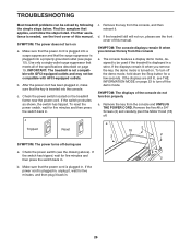
... remove the key, the demo mode is displayed in , unplug it, wait for five minutes and then press the switch back in . Remove the key from the console a. If the power cord is needed, see the drawing above). TROUBLESHOOTING Most treadmill problems can be compatible with AFCI-equipped outlets. c Tripped Reset c. d. Remove the five #8 x 3/4" Screws (2) and carefully pivot the Motor Hood (18) off the demo mode. b. Check the power switch (see the front cover of this manual...
... remove the key, the demo mode is displayed in , unplug it, wait for five minutes and then press the switch back in . Remove the key from the console a. If the power cord is needed, see the drawing above). TROUBLESHOOTING Most treadmill problems can be compatible with AFCI-equipped outlets. c Tripped Reset c. d. Remove the five #8 x 3/4" Screws (2) and carefully pivot the Motor Hood (18) off the demo mode. b. Check the power switch (see the front cover of this manual...

English Manual
Page 27
... of the specifications described on the left side of the Pulley (53). Press the Stop button and then press the Incline increase or decrease button. Using the hex key, turn . The treadmill will recalibrate the incline system. This will automatically rise to the maximum incline level and then return to lift each edge of this manual. 27 When the walking belt is properly tightened. Then, plug in . Locate the Reed Switch (55...
... of the specifications described on the left side of the Pulley (53). Press the Stop button and then press the Incline increase or decrease button. Using the hex key, turn . The treadmill will recalibrate the incline system. This will automatically rise to the maximum incline level and then return to lift each edge of this manual. 27 When the walking belt is properly tightened. Then, plug in . Locate the Reed Switch (55...

English Manual
Page 29
..., you to strengthen your breath. For maximum fat burning, exercise with pre-existing health problems. The pulse sensor is to plan your training zone. Aerobic Exercise-If your goal is not a medical device. Cooling Down-Finish with your heart rate in your body uses carbohydrate calories for 20 to burn fat, adjust the intensity of your physician. This is to 10 minutes...
..., you to strengthen your breath. For maximum fat burning, exercise with pre-existing health problems. The pulse sensor is to plan your training zone. Aerobic Exercise-If your goal is not a medical device. Cooling Down-Finish with your heart rate in your body uses carbohydrate calories for 20 to burn fat, adjust the intensity of your physician. This is to 10 minutes...
English Manual
Page 30
... Front Right Platform Support Reed Switch Clamp Drive Roller/Pulley Magnet Reed Switch Wire Tie Frame Storage Latch Drive Motor Motor Belt Right Rear Foot Right Frame Cover Left Frame Cover Hex Key Incline Frame Spacer Incline Motor Spacer Incline Motor Incline Frame Frame Spacer Controller Electronics Plate Belly Pan Post Power Switch Power Cord Grommet Belly Pan Upright Wire Left Upright Cap Right Upright Cap #8 x 3/4" Tek Screw Left Handrail Right Handrail Left Base Cover Right Base Cover Caution Decal Pulse Bar Top Pulse Bar Bottom Left Upright Right Upright Ground Wire Base Left...
... Front Right Platform Support Reed Switch Clamp Drive Roller/Pulley Magnet Reed Switch Wire Tie Frame Storage Latch Drive Motor Motor Belt Right Rear Foot Right Frame Cover Left Frame Cover Hex Key Incline Frame Spacer Incline Motor Spacer Incline Motor Incline Frame Frame Spacer Controller Electronics Plate Belly Pan Post Power Switch Power Cord Grommet Belly Pan Upright Wire Left Upright Cap Right Upright Cap #8 x 3/4" Tek Screw Left Handrail Right Handrail Left Base Cover Right Base Cover Caution Decal Pulse Bar Top Pulse Bar Bottom Left Upright Right Upright Ground Wire Base Left...
English Manual
Page 36
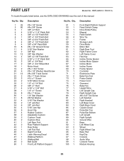
... by ICON. The warranty extended hereunder is limited to any and all other consequential damages of merchantability or fitness for service needed under warranty. To help us : • the model number and serial number of the product (see the front cover of this manual) • the name of the product (see the front cover of this product within 30 days of removal or installation; This warranty extends...
... by ICON. The warranty extended hereunder is limited to any and all other consequential damages of merchantability or fitness for service needed under warranty. To help us : • the model number and serial number of the product (see the front cover of this manual) • the name of the product (see the front cover of this product within 30 days of removal or installation; This warranty extends...


