Maintenance and Service Guide
Page 1
HP Chromebook 13 G1 Maintenance and Service Guide IMPORTANT! This document is intended for HP authorized service providers only.
HP Chromebook 13 G1 Maintenance and Service Guide IMPORTANT! This document is intended for HP authorized service providers only.

Maintenance and Service Guide
Page 5
Table of contents 1 Product description ...1 2 External component identification ...3 Display ...3 Button ...4 TouchPad ...5 Left side ...6 Right side ...7 3 Illustrated parts catalog ...8 Locating the product ID, serial number, and warranty information 8 Computer major components ...9 Display assembly subcomponents ...11 Miscellaneous parts ...13 4 Removal and replacement preliminary requirements 14 Tools required ...14 Service considerations ...14 Plastic parts ...14 Cables and connectors ...14 Drive handling ...15 Grounding guidelines ...16 Electrostatic discharge damage ...16 Packaging ...
Table of contents 1 Product description ...1 2 External component identification ...3 Display ...3 Button ...4 TouchPad ...5 Left side ...6 Right side ...7 3 Illustrated parts catalog ...8 Locating the product ID, serial number, and warranty information 8 Computer major components ...9 Display assembly subcomponents ...11 Miscellaneous parts ...13 4 Removal and replacement preliminary requirements 14 Tools required ...14 Service considerations ...14 Plastic parts ...14 Cables and connectors ...14 Drive handling ...15 Grounding guidelines ...16 Electrostatic discharge damage ...16 Packaging ...
Maintenance and Service Guide
Page 7
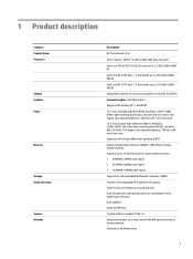
... -board system memory: ● 4096MB (128MBx32x2 x4pcs) ● 8192MB (256MBx16x4 x4pcs) ● 16384MB (128MBx32x4 x4pcs) Supports 32-GB embedded Multimedia Controller (eMMC) Fixed (no tilt) integrated HP TrueVision HD camera 1280×720 by 30 frames per second with LED Dual microphones with appropriate echo-cancellation, noisesuppression software Dual speakers Audio by B&O Play Trusted platform module (TPM) 1.2 Integrated wireless local area network (WLAN) options by...
... -board system memory: ● 4096MB (128MBx32x2 x4pcs) ● 8192MB (256MBx16x4 x4pcs) ● 16384MB (128MBx32x4 x4pcs) Supports 32-GB embedded Multimedia Controller (eMMC) Fixed (no tilt) integrated HP TrueVision HD camera 1280×720 by 30 frames per second with LED Dual microphones with appropriate echo-cancellation, noisesuppression software Dual speakers Audio by B&O Play Trusted platform module (TPM) 1.2 Integrated wireless local area network (WLAN) options by...

Maintenance and Service Guide
Page 8
... Ports Keyboard/pointing devices Power requirements Operating system Serviceability Description Supports the Intel Dual Band Wireless-AC 7265 802.11 ac 2X2 WiFi + Bluetooth® 4.2 WLAN module ● Two USB 3.1 Type-C ports (both enable power delivery) ● Headphone/microphone combo jack ● USB 3.0 port (1 on left side) ● USB 2.0/3.0 allocation; 3 for unit/ports, 1 for Camera Full-sized, textured, island-style, Google® backlit keyboard TouchPad: Multitouch gestures enabled Taps enabled as default Supports a 3-cell, 45-WHr, 3.25-WHr, polymer battery Supports...
... Ports Keyboard/pointing devices Power requirements Operating system Serviceability Description Supports the Intel Dual Band Wireless-AC 7265 802.11 ac 2X2 WiFi + Bluetooth® 4.2 WLAN module ● Two USB 3.1 Type-C ports (both enable power delivery) ● Headphone/microphone combo jack ● USB 3.0 port (1 on left side) ● USB 2.0/3.0 allocation; 3 for unit/ports, 1 for Camera Full-sized, textured, island-style, Google® backlit keyboard TouchPad: Multitouch gestures enabled Taps enabled as default Supports a 3-cell, 45-WHr, 3.25-WHr, polymer battery Supports...

Maintenance and Service Guide
Page 12
...support optional microphone-only devices. NOTE: When a device is connected to the computer, connect a USB device with a Type-C connector, and can charge products such as a keyboard, mouse, external drive, or USB hub. WARNING! NOTE: Be sure that the device cable has a 4-conductor connector that supports both audio-out (headphone) and audio-in (microphone) combo jack Description Connect a USB Type-C AC adapter to provide power to the jack, the computer speakers are disabled. Left side Item (1) (2) (3) (4) Component USB Type C power charging ports (2) AC adapter and battery light USB...
...support optional microphone-only devices. NOTE: When a device is connected to the computer, connect a USB device with a Type-C connector, and can charge products such as a keyboard, mouse, external drive, or USB hub. WARNING! NOTE: Be sure that the device cable has a 4-conductor connector that supports both audio-out (headphone) and audio-in (microphone) combo jack Description Connect a USB Type-C AC adapter to provide power to the jack, the computer speakers are disabled. Left side Item (1) (2) (3) (4) Component USB Type C power charging ports (2) AC adapter and battery light USB...
Maintenance and Service Guide
Page 17
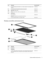
... (2) Display panel: 13.3-inch, full high-definition (FHD), AntiGlare, (1920×1080), UWVA, light-emitting diode (LED), ultraslim-flat (2.6-mm); 16:9 aspect ratio; typical brightness: 300 nits, eDP, nontouch only 859533-001 Display assembly subcomponents 11 Item Component Spare part number Intel Dual Band Wireless-AC 7265 802.11 ac 2×2 WiFi + Bluetooth 4.2 Combo Adapter (dual 793840-005 antennas) (9) SD card reader board (includes SD card reader slot and cable...
... (2) Display panel: 13.3-inch, full high-definition (FHD), AntiGlare, (1920×1080), UWVA, light-emitting diode (LED), ultraslim-flat (2.6-mm); 16:9 aspect ratio; typical brightness: 300 nits, eDP, nontouch only 859533-001 Display assembly subcomponents 11 Item Component Spare part number Intel Dual Band Wireless-AC 7265 802.11 ac 2×2 WiFi + Bluetooth 4.2 Combo Adapter (dual 793840-005 antennas) (9) SD card reader board (includes SD card reader slot and cable...

Maintenance and Service Guide
Page 20
... TouchPad could stop working , follow the steps to power on for the first time. these cables tear easily. 14 Chapter 4 Removal and replacement preliminary requirements Improper cable placement can damage plastic parts. Use care when handling the plastic parts. The TouchPad firmware updates when unit is turned on the unit completely until it reaches the Google login screen. NOTE: Before attempting to insert a USB recovery image, make sure...
... TouchPad could stop working , follow the steps to power on for the first time. these cables tear easily. 14 Chapter 4 Removal and replacement preliminary requirements Improper cable placement can damage plastic parts. Use care when handling the plastic parts. The TouchPad firmware updates when unit is turned on the unit completely until it reaches the Google login screen. NOTE: Before attempting to insert a USB recovery image, make sure...
Maintenance and Service Guide
Page 25
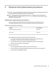
... removal and replacement. Computer feet and base enclosure Description Computer feet (included in the rubber kit) Spare part number 861673-001 Base enclosure 859526-001 Before replacing the computer feet and base enclosure, follow the on-screen instructions. Component replacement procedures 19 NOTE: HP continually improves and changes product parts. Disconnect the power from the computer by an authorized service provider. Disconnect all external devices...
... removal and replacement. Computer feet and base enclosure Description Computer feet (included in the rubber kit) Spare part number 861673-001 Base enclosure 859526-001 Before replacing the computer feet and base enclosure, follow the on-screen instructions. Component replacement procedures 19 NOTE: HP continually improves and changes product parts. Disconnect the power from the computer by an authorized service provider. Disconnect all external devices...

Maintenance and Service Guide
Page 27
... , and then shut it down through the operating system. 2. Disconnect the battery cable (1) from the computer. 3. includes cable) Spare part number 848212-850 Before removing the battery, follow these steps: 1. Disconnect all external devices from the computer. 4. Remove the battery: 1. If you are unsure whether the computer is off the computer. Remove the battery (3). Turn off or in Hibernation, turn the computer on page 19). Reverse...
... , and then shut it down through the operating system. 2. Disconnect the battery cable (1) from the computer. 3. includes cable) Spare part number 848212-850 Before removing the battery, follow these steps: 1. Disconnect all external devices from the computer. 4. Remove the battery: 1. If you are unsure whether the computer is off the computer. Remove the battery (3). Turn off or in Hibernation, turn the computer on page 19). Reverse...

Maintenance and Service Guide
Page 29
... WLAN module to restore device functionality, and then contact technical support. Remove the battery (see Battery on page 21). Remove the heat sink (see Computer feet and base enclosure on page 19). 5. WLAN module Description Intel Dual Band Wireless-AC 7265NV 802.11 ac 2×2 WiFi + Bluetooth 4.0 Combo Adapter Spare part number 793840-005 CAUTION: To prevent an unresponsive system, replace the wireless module only with a wireless module authorized for use in...
... WLAN module to restore device functionality, and then contact technical support. Remove the battery (see Battery on page 21). Remove the heat sink (see Computer feet and base enclosure on page 19). 5. WLAN module Description Intel Dual Band Wireless-AC 7265NV 802.11 ac 2×2 WiFi + Bluetooth 4.0 Combo Adapter Spare part number 793840-005 CAUTION: To prevent an unresponsive system, replace the wireless module only with a wireless module authorized for use in...
Maintenance and Service Guide
Page 30
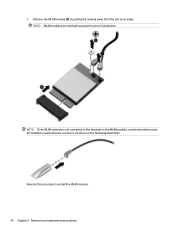
NOTE: If the WLAN antenna is not connected to install the WLAN module. 24 Chapter 5 Removal and replacement procedures Remove the WLAN module (3) by pulling the module away from the slot at an angle. Reverse this procedure to the terminal on the WLAN module, a protective sleeve must be installed on each antenna connector, as shown in the following illustration. NOTE: WLAN modules are notched to prevent incorrect installation. 3.
NOTE: If the WLAN antenna is not connected to install the WLAN module. 24 Chapter 5 Removal and replacement procedures Remove the WLAN module (3) by pulling the module away from the slot at an angle. Reverse this procedure to the terminal on the WLAN module, a protective sleeve must be installed on each antenna connector, as shown in the following illustration. NOTE: WLAN modules are notched to prevent incorrect installation. 3.
Maintenance and Service Guide
Page 31
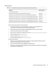
...-001 Before removing the system board, follow these steps: 1. Remove the battery (see WLAN module on page 21). 6. Disconnect the power from the computer by unplugging the power cord from the system board. 3. Remove the heat sink (see Computer feet and base enclosure on all external devices from the computer. 4. Disconnect the TouchPad connector cable (2) from the computer. 3. Description Spare part number For use on page...
...-001 Before removing the system board, follow these steps: 1. Remove the battery (see WLAN module on page 21). 6. Disconnect the power from the computer by unplugging the power cord from the system board. 3. Remove the heat sink (see Computer feet and base enclosure on all external devices from the computer. 4. Disconnect the TouchPad connector cable (2) from the computer. 3. Description Spare part number For use on page...

Maintenance and Service Guide
Page 33
... external devices from the computer. 3. Disconnect the speaker cables (1). 2. Remove the two computer feet and base enclosure (see Heat sink on page 19). 5. Remove the speakers (2). Remove the battery (see Battery on , and then shut it down through the operating system. 2. Component replacement procedures 27 Turn off or in Hibernation, turn the computer on page 21). 6. Speakers Description Speaker Kit (includes cables) Spare part number...
... external devices from the computer. 3. Disconnect the speaker cables (1). 2. Remove the two computer feet and base enclosure (see Heat sink on page 19). 5. Remove the speakers (2). Remove the battery (see Battery on , and then shut it down through the operating system. 2. Component replacement procedures 27 Turn off or in Hibernation, turn the computer on page 21). 6. Speakers Description Speaker Kit (includes cables) Spare part number...

Maintenance and Service Guide
Page 34
... install the SD card reader board. 28 Chapter 5 Removal and replacement procedures Remove the battery (see Heat sink on , and then shut it down the computer. Reverse this procedure to which the SD card reader board cable is off or in Hibernation, turn the computer on page 21). 7. Remove the WLAN module (see Computer feet and base enclosure on page 19). 5. SD card reader board Description SD card reader board Spare part number...
... install the SD card reader board. 28 Chapter 5 Removal and replacement procedures Remove the battery (see Heat sink on , and then shut it down the computer. Reverse this procedure to which the SD card reader board cable is off or in Hibernation, turn the computer on page 21). 7. Remove the WLAN module (see Computer feet and base enclosure on page 19). 5. SD card reader board Description SD card reader board Spare part number...

Maintenance and Service Guide
Page 36
...). 6. Remove the speakers (see Battery on page 27). 10. Remove the keyboard/top cover. Disconnect the power from the computer by unplugging the power cord from the computer. 4. Remove the two computer feet and base enclosure (see System board on , and then shut it down through the operating system. 2. Remove the SD card reader board SD card reader board on page 23). 8. Description For use in Belgium For use...
...). 6. Remove the speakers (see Battery on page 27). 10. Remove the keyboard/top cover. Disconnect the power from the computer by unplugging the power cord from the computer. 4. Remove the two computer feet and base enclosure (see System board on , and then shut it down through the operating system. 2. Remove the SD card reader board SD card reader board on page 23). 8. Description For use in Belgium For use...

Maintenance and Service Guide
Page 37
... left and right hinges and caps) Cable (LVDS QHD+) HD camera/microphone module Display enclosure (includes antennas, rubber padding, and shielding) Spare part number 859529-001 859533-001 859534-001 859530-001 861672-001 861692-001 859532-001 IMPORTANT: Make special note of each screw and screw lock size and location during removal and replacement. Disconnect the power from the computer by unplugging the...
... left and right hinges and caps) Cable (LVDS QHD+) HD camera/microphone module Display enclosure (includes antennas, rubber padding, and shielding) Spare part number 859529-001 859533-001 859534-001 859530-001 861672-001 861692-001 859532-001 IMPORTANT: Make special note of each screw and screw lock size and location during removal and replacement. Disconnect the power from the computer by unplugging the...
Maintenance and Service Guide
Page 47
... part number hinge spare part number 10, 21 12 J jacks audio-in 6 audio-out 6 headphone 6 microphone 6 K keyboard/top cover removal 30 spare part numbers 10, 30 L left-side component 6 lights webcam 3 M memory, product description 1 microphone location 3 product description 1 microphone jack 6 microphone module removal 34 model name 1 O operating system, product description 2 P packaging guidelines 17 plastic parts, service considerations 14 ports product description 2 power button 4 power cord requirements for all countries 37 requirements for specific countries and regions 38 set...
... part number hinge spare part number 10, 21 12 J jacks audio-in 6 audio-out 6 headphone 6 microphone 6 K keyboard/top cover removal 30 spare part numbers 10, 30 L left-side component 6 lights webcam 3 M memory, product description 1 microphone location 3 product description 1 microphone jack 6 microphone module removal 34 model name 1 O operating system, product description 2 P packaging guidelines 17 plastic parts, service considerations 14 ports product description 2 power button 4 power cord requirements for all countries 37 requirements for specific countries and regions 38 set...
Maintenance and Service Guide
Page 48
memory 1 microphone 1 operating system 2 ports 2 power requirements 2 processors 1 product name 1 sensors 1 serviceability 2 storage 1 video 1 wireless 1 product name 1 R removal/replacement procedures 19 right-side components 7 Rubber Kit, spare part numbers 11, 13 W webcam light 3 webcam module removal 34 spare part number 35 webcam, location 3 webcam/microphone module spare part number 12 wireless antenna location 3 wireless, product description 1 WLAN antenna location 3 WLAN module removal 23 spare part numbers 10, 23 workstation guidelines 17 S Screw Kit, spare part number 13 sensors, ...
memory 1 microphone 1 operating system 2 ports 2 power requirements 2 processors 1 product name 1 sensors 1 serviceability 2 storage 1 video 1 wireless 1 product name 1 R removal/replacement procedures 19 right-side components 7 Rubber Kit, spare part numbers 11, 13 W webcam light 3 webcam module removal 34 spare part number 35 webcam, location 3 webcam/microphone module spare part number 12 wireless antenna location 3 wireless, product description 1 WLAN antenna location 3 WLAN module removal 23 spare part numbers 10, 23 workstation guidelines 17 S Screw Kit, spare part number 13 sensors, ...
User Guide
Page 16
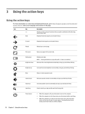
... Brightness down the key. Brightness up Search key Increases speaker volume incrementally as long as you hold down the key. Press to https://support.google.com/chromebook/ answer/183101. Reload Reloads your apps and the web from the apps list. Decreases the screen brightness incrementally as long as you see the sign-in full-screen mode. Mute Mutes or restores speaker sound. Pressing the power button during screen-lock mode turns...
... Brightness down the key. Brightness up Search key Increases speaker volume incrementally as long as you hold down the key. Press to https://support.google.com/chromebook/ answer/183101. Reload Reloads your apps and the web from the apps list. Decreases the screen brightness incrementally as long as you see the sign-in full-screen mode. Mute Mutes or restores speaker sound. Pressing the power button during screen-lock mode turns...
User Guide
Page 23
...7 serial number 6 service 6 wireless certification 7 WLAN 7 lights AC adapter and battery 2 camera 3 lights, identifying 3 M memory card reader, identifying 1 memory card, identifying 1 microphone (audio-in) jack, identifying 2 N Next window 10 P ports USB Type-C charging 2 power button, identifying 5 printing 13 product name and number, computer 6 R regulatory information regulatory label 7 wireless certification labels 7 S scrolling TouchPad gesture 9 serial number 6 serial number, computer 6 service labels, locating 6 slots memory card reader 1 speakers, identifying 6 Support 14 T TouchPad...
...7 serial number 6 service 6 wireless certification 7 WLAN 7 lights AC adapter and battery 2 camera 3 lights, identifying 3 M memory card reader, identifying 1 memory card, identifying 1 microphone (audio-in) jack, identifying 2 N Next window 10 P ports USB Type-C charging 2 power button, identifying 5 printing 13 product name and number, computer 6 R regulatory information regulatory label 7 wireless certification labels 7 S scrolling TouchPad gesture 9 serial number 6 serial number, computer 6 service labels, locating 6 slots memory card reader 1 speakers, identifying 6 Support 14 T TouchPad...


