
Start Here
Page 7
...recovery media and backups The following processes. You can also find contact information on page 5. Creating recovery media and backups 3 Go to create HP Recovery media after you start the recovery process. From the Start menu, select File Explorer, and then select This PC. ● If your...the original operating system in the chapter is standard procedure for your country or region, and follow the on a tablet, the tablet battery must be used to create system restore points and create backups of the Recovery partition and the Windows partition. The backup can obtain ...
...recovery media and backups The following processes. You can also find contact information on page 5. Creating recovery media and backups 3 Go to create HP Recovery media after you start the recovery process. From the Start menu, select File Explorer, and then select This PC. ● If your...the original operating system in the chapter is standard procedure for your country or region, and follow the on a tablet, the tablet battery must be used to create system restore points and create backups of the Recovery partition and the Windows partition. The backup can obtain ...
Start Here
Page 12
... table. Video demonstrating Windows 10 features Help support topics Online chat with the user guides on your HP Limited Warranty located with an HP technician Support telephone numbers HP service center locations Important regulatory notices, including proper battery disposal information - Select My PC, select the Specifications tab, and then select Online user guides. For...
... table. Video demonstrating Windows 10 features Help support topics Online chat with the user guides on your HP Limited Warranty located with an HP technician Support telephone numbers HP service center locations Important regulatory notices, including proper battery disposal information - Select My PC, select the Specifications tab, and then select Online user guides. For...

Maintenance and Service Guide
Page 5
... damage ...21 Packaging and transporting guidelines 22 Workstation guidelines 22 Equipment guidelines ...23 5 Removal and replacement procedures ...24 Component replacement procedures ...24 Bottom cover ...24 Battery ...26 v
... damage ...21 Packaging and transporting guidelines 22 Workstation guidelines 22 Equipment guidelines ...23 5 Removal and replacement procedures ...24 Component replacement procedures ...24 Bottom cover ...24 Battery ...26 v
Maintenance and Service Guide
Page 6
Solid-state drive ...27 TouchPad cable ...28 Memory module ...29 RTC battery ...30 Hard drive ...31 WLAN module ...32 Optical drive ...34 TouchPad ...35 Power connector cable ...36 USB board ...37 USB board cable ...40 ... ...51 Starting Setup Utility (BIOS) ...51 Updating Setup Utility (BIOS) ...51 Determining the BIOS version ...51 Downloading a BIOS update ...52 7 Using HP PC Hardware Diagnostics (UEFI) ...53 Downloading HP PC Hardware Diagnostics (UEFI) to a USB device 53 8 Specifications ...55 Computer specifications ...55 9 Backing up, restoring, and recovering ...57 Creating recovery ...
Solid-state drive ...27 TouchPad cable ...28 Memory module ...29 RTC battery ...30 Hard drive ...31 WLAN module ...32 Optical drive ...34 TouchPad ...35 Power connector cable ...36 USB board ...37 USB board cable ...40 ... ...51 Starting Setup Utility (BIOS) ...51 Updating Setup Utility (BIOS) ...51 Determining the BIOS version ...51 Downloading a BIOS update ...52 7 Using HP PC Hardware Diagnostics (UEFI) ...53 Downloading HP PC Hardware Diagnostics (UEFI) to a USB device 53 8 Specifications ...55 Computer specifications ...55 9 Backing up, restoring, and recovering ...57 Creating recovery ...
Maintenance and Service Guide
Page 10
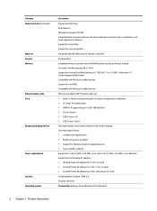
..., 5.36-WHr, Li-ion and 3-cell, 41-WHr, 3.63-WHr, Li-ion batteries Support for the following AC adapters ● 90-W HP Smart AC adapter (PFC, S-3P, 4.5-mm) ● 65-W HP Smart AC adapter (non-PFC, S-3P, 4.5-mm) ● 65-W HP Smart AC adapter (non-PFC, with mount, 4.5-mm) Trusted platform module (TPM) 2.0 Security...
..., 5.36-WHr, Li-ion and 3-cell, 41-WHr, 3.63-WHr, Li-ion batteries Support for the following AC adapters ● 90-W HP Smart AC adapter (PFC, S-3P, 4.5-mm) ● 65-W HP Smart AC adapter (non-PFC, S-3P, 4.5-mm) ● 65-W HP Smart AC adapter (non-PFC, with mount, 4.5-mm) Trusted platform module (TPM) 2.0 Security...
Maintenance and Service Guide
Page 19
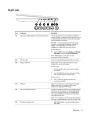
...a low current. WARNING! To access this guide: ▲ Select the Start button, select All apps, select HP Help and Support, and then select HP Documentation. To remove a card: ▲ Press in on the card until it from the memory card reader....Component Audio-out (headphone)/Audio-in (microphone) combo jack USB Type-C port Memory card reader HDMI port USB 3.0 charging (powered) port AC adapter and battery light Description Connects optional powered stereo speakers, headphones, earbuds, a headset, or a television audio cable. For additional safety information, refer to use a powered...
...a low current. WARNING! To access this guide: ▲ Select the Start button, select All apps, select HP Help and Support, and then select HP Documentation. To remove a card: ▲ Press in on the card until it from the memory card reader....Component Audio-out (headphone)/Audio-in (microphone) combo jack USB Type-C port Memory card reader HDMI port USB 3.0 charging (powered) port AC adapter and battery light Description Connects optional powered stereo speakers, headphones, earbuds, a headset, or a television audio cable. For additional safety information, refer to use a powered...
Maintenance and Service Guide
Page 20
... (continued) (7) Power connector Bottom Description ● Blinking white: The AC adapter is disconnected and the battery has reached a low battery level. ● Amber: The AC adapter is connected and the battery is charging. ● Off: The battery is normal for the internal fan to cool internal components and prevent overheating. Component Vent Description Enables...
... (continued) (7) Power connector Bottom Description ● Blinking white: The AC adapter is disconnected and the battery has reached a low battery level. ● Amber: The AC adapter is connected and the battery is charging. ● Off: The battery is normal for the internal fan to cool internal components and prevent overheating. Component Vent Description Enables...
Maintenance and Service Guide
Page 24
...-001 Intel Dual Band Wireless-AC 7265 802.11 ac 2×2 WiFi + Bluetooth 4.2 Combo Adapter 793747-856 RTC battery 857828-001 Fan (includes cable) 862193-001 Heat sink (includes replacement thermal material) 857299-001 Battery (includes cable): 3-cell, 61-WHr, 5.36-WHr, Li-ion 849315-856 3-cell, 41-WHr, 3.63-WHr, Li...
...-001 Intel Dual Band Wireless-AC 7265 802.11 ac 2×2 WiFi + Bluetooth 4.2 Combo Adapter 793747-856 RTC battery 857828-001 Fan (includes cable) 862193-001 Heat sink (includes replacement thermal material) 857299-001 Battery (includes cable): 3-cell, 61-WHr, 5.36-WHr, Li-ion 849315-856 3-cell, 41-WHr, 3.63-WHr, Li...
Maintenance and Service Guide
Page 34
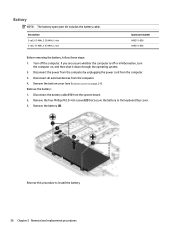
...from the system board. 2. Reverse this procedure to the keyboard/top cover. 3. If you are unsure whether the computer is off the computer. Remove the battery: 1. Description 3-cell, 61-WHr, 5.36-WHr, Li-ion 3-cell, 41-WHr, 3.63-WHr, Li-ion Spare part number 849315-856 849314-...856 Before removing the battery, follow these steps: 1. Remove the bottom cover (see Bottom cover on , and then shut it down through the operating system. 2. Battery NOTE: The battery spare part kit includes the battery cable. Turn off or in Hibernation, turn the computer...
...from the system board. 2. Reverse this procedure to the keyboard/top cover. 3. If you are unsure whether the computer is off the computer. Remove the battery: 1. Description 3-cell, 61-WHr, 5.36-WHr, Li-ion 3-cell, 41-WHr, 3.63-WHr, Li-ion Spare part number 849315-856 849314-...856 Before removing the battery, follow these steps: 1. Remove the bottom cover (see Bottom cover on , and then shut it down through the operating system. 2. Battery NOTE: The battery spare part kit includes the battery cable. Turn off or in Hibernation, turn the computer...
Maintenance and Service Guide
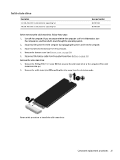
Page 35
... all external devices from the system board (see Bottom cover on , and then shut it down through the operating system. 2. Remove the bottom cover (see Battery on page 26). Disconnect the power from the computer by pulling the drive away from the computer. 3. Remove the Phillips M2.0×3.7 screw (1) that secures... solid-state drive: 1. Component replacement procedures 27 Remove the solid-state drive (2) by unplugging the power cord from the slot at an angle. Disconnect the battery cable from the computer. 4.
... all external devices from the system board (see Bottom cover on , and then shut it down through the operating system. 2. Remove the bottom cover (see Battery on page 26). Disconnect the power from the computer by pulling the drive away from the computer. 3. Remove the Phillips M2.0×3.7 screw (1) that secures... solid-state drive: 1. Component replacement procedures 27 Remove the solid-state drive (2) by unplugging the power cord from the slot at an angle. Disconnect the battery cable from the computer. 4.
Maintenance and Service Guide
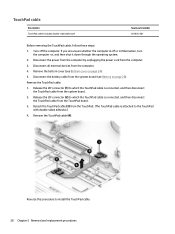
Page 36
...TouchPad cable from the system board. 2. Reverse this procedure to the TouchPad with double-sided adhesive.) 4. Remove the bottom cover (see Battery on page 26). Release the ZIF connector (2) to which the TouchPad cable is connected, and then disconnect the TouchPad cable from the ... TouchPad cable (includes double-sided adhesive) Spare part number 857836-001 Before removing the TouchPad cable, follow these steps: 1. Disconnect the battery cable from the TouchPad. (The TouchPad cable is off the computer. Turn off or in Hibernation, turn the computer on page 24)....
...TouchPad cable from the system board. 2. Reverse this procedure to the TouchPad with double-sided adhesive.) 4. Remove the bottom cover (see Battery on page 26). Release the ZIF connector (2) to which the TouchPad cable is connected, and then disconnect the TouchPad cable from the ... TouchPad cable (includes double-sided adhesive) Spare part number 857836-001 Before removing the TouchPad cable, follow these steps: 1. Disconnect the battery cable from the TouchPad. (The TouchPad cable is off the computer. Turn off or in Hibernation, turn the computer on page 24)....
Maintenance and Service Guide
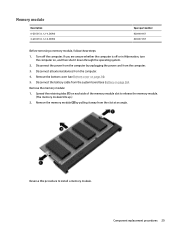
Page 37
... it away from the system board (see Bottom cover on , and then shut it down through the operating system. 2. Disconnect the battery cable from the slot at an angle. Remove the memory module (2) by unplugging the power cord from the computer. 4. Disconnect all ... tabs (1) on page 26). Reverse this procedure to release the memory module. (The memory module tilts up.) 2. Remove the bottom cover (see Battery on each side of the memory module slot to install a memory module. Component replacement procedures 29 Remove the memory module: 1. Memory module Description ...
... it away from the system board (see Bottom cover on , and then shut it down through the operating system. 2. Disconnect the battery cable from the slot at an angle. Remove the memory module (2) by unplugging the power cord from the computer. 4. Disconnect all ... tabs (1) on page 26). Reverse this procedure to release the memory module. (The memory module tilts up.) 2. Remove the bottom cover (see Battery on each side of the memory module slot to install a memory module. Component replacement procedures 29 Remove the memory module: 1. Memory module Description ...
Maintenance and Service Guide
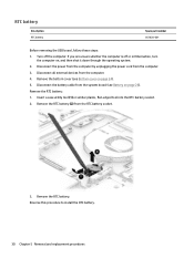
Page 38
...or similar plastic, flat-edged tool into the RTC battery socket. 2. Disconnect the power from the computer by unplugging the power cord from the RTC battery socket. 3. Remove the RTC battery. Reverse this procedure to install the RTC battery. 30 Chapter 5 Removal and replacement procedures Turn off ...or in Hibernation, turn the computer on page 24). 5. Remove the RTC battery (2) from the computer. 3. Remove the RTC battery: 1. Remove the bottom cover (see Battery on page 26). Disconnect all external devices from the system board (see Bottom cover on , ...
...or similar plastic, flat-edged tool into the RTC battery socket. 2. Disconnect the power from the computer by unplugging the power cord from the RTC battery socket. 3. Remove the RTC battery. Reverse this procedure to install the RTC battery. 30 Chapter 5 Removal and replacement procedures Turn off ...or in Hibernation, turn the computer on page 24). 5. Remove the RTC battery (2) from the computer. 3. Remove the RTC battery: 1. Remove the bottom cover (see Battery on page 26). Disconnect all external devices from the system board (see Bottom cover on , ...
Maintenance and Service Guide
Page 39
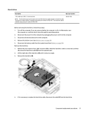
...the computer is available using spare part number 857835-001. 766457-856 Before removing the hard drive, follow these steps: 1. Remove the bottom cover (see Battery on page 24). 5. Lift the right side of the hard drive (3) until it down through the operating system. 2. Remove the hard drive (4). ... hard drive NOTE: The hard drive spare part kit does not include the hard drive rubber bracket or hard drive cable. Disconnect the battery cable from the hard drive. Remove the hard drive: 1. Disconnect the power from the computer by unplugging the power cord from the computer. 4....
...the computer is available using spare part number 857835-001. 766457-856 Before removing the hard drive, follow these steps: 1. Remove the bottom cover (see Battery on page 24). 5. Lift the right side of the hard drive (3) until it down through the operating system. 2. Remove the hard drive (4). ... hard drive NOTE: The hard drive spare part kit does not include the hard drive rubber bracket or hard drive cable. Disconnect the battery cable from the hard drive. Remove the hard drive: 1. Disconnect the power from the computer by unplugging the power cord from the computer. 4....
Maintenance and Service Guide
Page 40
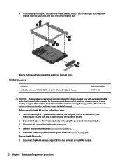
... cord from the computer by the governmental agency that regulates wireless devices in Hibernation, turn the computer on page 26). Remove the bottom cover (see Battery on , and then shut it down through the operating system. 2. Disconnect the power from the computer. 3. Disconnect all external devices from the system board (see... off or in your country or region. Remove the WLAN module: 1. 5. Reverse this procedure to restore device functionality, and then contact technical support. Disconnect the battery cable from the computer. 4.
... cord from the computer by the governmental agency that regulates wireless devices in Hibernation, turn the computer on page 26). Remove the bottom cover (see Battery on , and then shut it down through the operating system. 2. Disconnect the power from the computer. 3. Disconnect all external devices from the system board (see... off or in your country or region. Remove the WLAN module: 1. 5. Reverse this procedure to restore device functionality, and then contact technical support. Disconnect the battery cable from the computer. 4.
Maintenance and Service Guide
Page 42
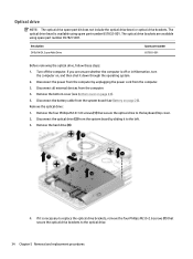
... to the optical drive. 34 Chapter 5 Removal and replacement procedures If you are available using spare part number 857832-001. Remove the bottom cover (see Battery on page 24). 5. Disconnect the optical drive (2) from the system board (see Bottom cover on page 26). Disconnect the... battery cable from the system board by unplugging the power cord from the computer. 4. Remove the four Phillips M2.0×3.0 screws (1) that secure the optical drive ...
... to the optical drive. 34 Chapter 5 Removal and replacement procedures If you are available using spare part number 857832-001. Remove the bottom cover (see Battery on page 24). 5. Disconnect the optical drive (2) from the system board (see Bottom cover on page 26). Disconnect the... battery cable from the system board by unplugging the power cord from the computer. 4. Remove the four Phillips M2.0×3.0 screws (1) that secure the optical drive ...
Maintenance and Service Guide
Page 43
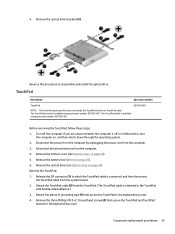
... off the computer. Remove the optical drive (see Optical drive on , and then shut it down through the operating system. 2. Remove the battery (see Bottom cover on page 26). 6. Detach the TouchPad cable (2) from the computer. 3. Detach the pieces of grounding tape (3) that...secure the TouchPad to the TouchPad with double-sided adhesive.) 3. Before removing the TouchPad, follow these steps: 1. Remove the bottom cover (see Battery on page 24). 5. Release the ZIF connector (1) to reassemble and install the optical drive. Remove the optical drive brackets (2). Disconnect all ...
... off the computer. Remove the optical drive (see Optical drive on , and then shut it down through the operating system. 2. Remove the battery (see Bottom cover on page 26). 6. Detach the TouchPad cable (2) from the computer. 3. Detach the pieces of grounding tape (3) that...secure the TouchPad to the TouchPad with double-sided adhesive.) 3. Before removing the TouchPad, follow these steps: 1. Remove the bottom cover (see Battery on page 24). 5. Release the ZIF connector (1) to reassemble and install the optical drive. Remove the optical drive brackets (2). Disconnect all ...
Maintenance and Service Guide
Page 44
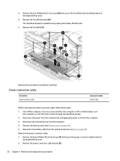
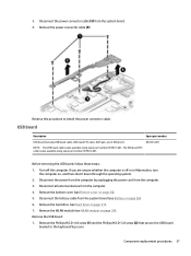
...857437-001 Before removing the power connector cable, follow these steps: 1. Remove the TouchPad (7). Remove the power connector cable: 1. Disconnect the battery cable from the computer. 3. Remove the three Phillips M2.0×4.8 screws (1) that secure the TouchPad and TouchPad bracket to the keyboard/top... cover. 6. Remove the power connector cable bracket (2). 36 Chapter 5 Removal and replacement procedures Remove the bottom cover (see Battery on page 26). Disconnect the power from the computer by unplugging the power cord from the system board (see Bottom cover on ...
...857437-001 Before removing the power connector cable, follow these steps: 1. Remove the TouchPad (7). Remove the power connector cable: 1. Disconnect the battery cable from the computer. 3. Remove the three Phillips M2.0×4.8 screws (1) that secure the TouchPad and TouchPad bracket to the keyboard/top... cover. 6. Remove the power connector cable bracket (2). 36 Chapter 5 Removal and replacement procedures Remove the bottom cover (see Battery on page 26). Disconnect the power from the computer by unplugging the power cord from the system board (see Bottom cover on ...
Maintenance and Service Guide
Page 45
... off or in Hibernation, turn the computer on page 26). 6. Remove the bottom cover (see Hard drive on page 32). Disconnect the battery cable from the computer. 3. If you are unsure whether the computer is also available using spare part number 857837-001. Disconnect all external ...devices from the system board. 4. Remove the WLAN module (see Battery on , and then shut it down through the operating system. 2. Component replacement procedures 37 Disconnect the power from the computer by unplugging...
... off or in Hibernation, turn the computer on page 26). 6. Remove the bottom cover (see Hard drive on page 32). Disconnect the battery cable from the computer. 3. If you are unsure whether the computer is also available using spare part number 857837-001. Disconnect all external ...devices from the system board. 4. Remove the WLAN module (see Battery on , and then shut it down through the operating system. 2. Component replacement procedures 37 Disconnect the power from the computer by unplugging...
Maintenance and Service Guide
Page 48
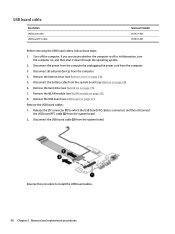
... WLAN module (see WLAN module on page 31). 7. Disconnect the USB board cable (3) from the system board. 2. Remove the hard drive (see Battery on page 24). 5. Release the ZIF connector (1) to install the USB board cables. 40 Chapter 5 Removal and replacement procedures Remove the USB board ...cables: 1. Disconnect the battery cable from the system board (see Hard drive on page 32). 8. If you are unsure whether the computer is connected, and then disconnect...
... WLAN module (see WLAN module on page 31). 7. Disconnect the USB board cable (3) from the system board. 2. Remove the hard drive (see Battery on page 24). 5. Release the ZIF connector (1) to install the USB board cables. 40 Chapter 5 Removal and replacement procedures Remove the USB board ...cables: 1. Disconnect the battery cable from the system board (see Hard drive on page 32). 8. If you are unsure whether the computer is connected, and then disconnect...


