

Maintenance and Service Guide
Page 61
...by the incorrect use GUID Partition Table (GPT) format, which better supports large hard drives. Secure Platform Management (SPM) ● HP Sure Run Current State ● SPM Current State Physical Presence Interference When selected, the user is running at system power up when changes...(F10) Utilities 53 Any anomalies detected in a Sure Start security event being generated. ● Sure Start Security Event Policy - enables monitoring of HP system firmware executing out of main memory while the operating system is also protected from a disk and to allocate private regions of memory, ...
...by the incorrect use GUID Partition Table (GPT) format, which better supports large hard drives. Secure Platform Management (SPM) ● HP Sure Run Current State ● SPM Current State Physical Presence Interference When selected, the user is running at system power up when changes...(F10) Utilities 53 Any anomalies detected in a Sure Start security event being generated. ● Sure Start Security Event Policy - enables monitoring of HP system firmware executing out of main memory while the operating system is also protected from a disk and to allocate private regions of memory, ...

Maintenance and Service Guide
Page 115
... Startup Menu" message is a feature to ensure that only authenticated code can use the HP Sure Start default configuration. Turn on -screen instructions. c. If the BIOS becomes corrupted or is configured and already enabled so that continuously monitors your product, and then follow the on -screen instructions. 7. IMPORTANT: Resetting will result in...
... Startup Menu" message is a feature to ensure that only authenticated code can use the HP Sure Start default configuration. Turn on -screen instructions. c. If the BIOS becomes corrupted or is configured and already enabled so that continuously monitors your product, and then follow the on -screen instructions. 7. IMPORTANT: Resetting will result in...
Hardware Reference Guide
Page 5
...Serial and product number locations ...4 2 Setup ...5 Installing the monitor head ...5 Connecting the power supply ...8 Enabling the monitor head detection warning ...9 Installing a security cable ...9 Adjusting the monitor head position ...10 Connecting a secondary monitor ...11 Using the webcam ...12 Webcam operation ...12 Setting... ...14 Additional information ...14 Removing and replacing the base unit access covers 15 Removing and replacing the monitor head ...17 Locating internal components ...21 Removing and installing memory ...21 Memory module specifications ...21 Populating memory...
...Serial and product number locations ...4 2 Setup ...5 Installing the monitor head ...5 Connecting the power supply ...8 Enabling the monitor head detection warning ...9 Installing a security cable ...9 Adjusting the monitor head position ...10 Connecting a secondary monitor ...11 Using the webcam ...12 Webcam operation ...12 Setting... ...14 Additional information ...14 Removing and replacing the base unit access covers 15 Removing and replacing the monitor head ...17 Locating internal components ...21 Removing and installing memory ...21 Memory module specifications ...21 Populating memory...

Hardware Reference Guide
Page 9
Monitor front components (select products only) Components (1) Webcam (2) On-screen display buttons (for adjusting the screen) Webcam components Infrared (IR) webcam (optional) Components Front View (1) Webcam light (2) IR light (3) Full High Definition (FHD) webcam Top view (6) Digital microphones Rear view (7) Webcam light (4) IR webcam (5) Rear webcam adjustment wheel (8) FHD webcam Monitor front components (select products only) 3
Monitor front components (select products only) Components (1) Webcam (2) On-screen display buttons (for adjusting the screen) Webcam components Infrared (IR) webcam (optional) Components Front View (1) Webcam light (2) IR light (3) Full High Definition (FHD) webcam Top view (6) Digital microphones Rear view (7) Webcam light (4) IR webcam (5) Rear webcam adjustment wheel (8) FHD webcam Monitor front components (select products only) 3

Hardware Reference Guide
Page 11
... of the computer. 4. You must disconnect the power cord and wait approximately 30 seconds for the power to drain to avoid damage to access the monitor head installed in the standalone computer base. To remove the rear access cover to the internal components of the cover up (2). Disconnect the power cord... 5 IMPORTANT: Regardless of the power-on state, voltage is plugged into an active AC outlet. 2 Setup Installing the monitor head A monitor head can then be installed in a different computer, press the two release buttons on the system board as long as USB flash drives, from the...
... of the computer. 4. You must disconnect the power cord and wait approximately 30 seconds for the power to drain to avoid damage to access the monitor head installed in the standalone computer base. To remove the rear access cover to the internal components of the cover up (2). Disconnect the power cord... 5 IMPORTANT: Regardless of the power-on state, voltage is plugged into an active AC outlet. 2 Setup Installing the monitor head A monitor head can then be installed in a different computer, press the two release buttons on the system board as long as USB flash drives, from the...

Hardware Reference Guide
Page 12
Then, slide the cover back to remove it from the computer, press the two release buttons on the rear of the base unit (1), and at the same time rotate the rear of the cable connectors (1) and pulling the cable connectors up (2). Turn the cover over. Lift the tab on the two ends of the cover up and off the system board (2). 6. Disconnect the two monitor cables attached to the system board by squeezing firmly inward on the blank, and then slide the blank away from the rear cover to remove it . 6 Chapter 2 Setup To remove the rear access cover from the computer (3). 7. 5.
Then, slide the cover back to remove it from the computer, press the two release buttons on the rear of the base unit (1), and at the same time rotate the rear of the cable connectors (1) and pulling the cable connectors up (2). Turn the cover over. Lift the tab on the two ends of the cover up and off the system board (2). 6. Disconnect the two monitor cables attached to the system board by squeezing firmly inward on the blank, and then slide the blank away from the rear cover to remove it . 6 Chapter 2 Setup To remove the rear access cover from the computer (3). 7. 5.

Hardware Reference Guide
Page 13
...and being damaged. 9. Loosen the two captive screws at the base of the monitor head's neck onto the bracket on the base unit and slide the monitor forward (1) with one hand and place the base of the monitor head's neck (1). Make sure you are holding onto the bottom of the... monitor head from falling over and being damaged. Installing the monitor head 7 While holding the monitor head firmly when removing it to the base unit (2). Then tighten the two captive screws that secure the monitor head's neck to prevent the monitor head from the front with...
...and being damaged. 9. Loosen the two captive screws at the base of the monitor head's neck onto the bracket on the base unit and slide the monitor forward (1) with one hand and place the base of the monitor head's neck (1). Make sure you are holding onto the bottom of the... monitor head from falling over and being damaged. Installing the monitor head 7 While holding the monitor head firmly when removing it to the base unit (2). Then tighten the two captive screws that secure the monitor head's neck to prevent the monitor head from the front with...

Hardware Reference Guide
Page 14
... connector on the computer. Reconnect the power cord and any external devices, and then turn on the computer base unit (3). 8 Chapter 2 Setup Connect the two monitor cables to prevent damage when the cover is replaced. 12. 10. Connecting the power supply To connect the power supply, connect one end of the...
... connector on the computer. Reconnect the power cord and any external devices, and then turn on the computer base unit (3). 8 Chapter 2 Setup Connect the two monitor cables to prevent damage when the cover is replaced. 12. 10. Connecting the power supply To connect the power supply, connect one end of the...

Hardware Reference Guide
Page 15
...on or restart the computer, and when the HP logo appears, press f10 to save your desk (or other stationary object) and the other end of the cable to the security cable slot on systems with the key. Enabling the monitor head detection warning 9 Select Advanced, and ...Attach one end of the cable to your settings. Secure the security cable lock with an installed monitor head. 1. Enabling the monitor head detection warning This warning is enabled on the computer base unit. HP recommends ensuring that has a wire cable attached. Your changes take effect when the computer restarts....
...on or restart the computer, and when the HP logo appears, press f10 to save your desk (or other stationary object) and the other end of the cable to the security cable slot on systems with the key. Enabling the monitor head detection warning 9 Select Advanced, and ...Attach one end of the cable to your settings. Secure the security cable lock with an installed monitor head. 1. Enabling the monitor head detection warning This warning is enabled on the computer base unit. HP recommends ensuring that has a wire cable attached. Your changes take effect when the computer restarts....

Hardware Reference Guide
Page 16
Adjusting the monitor head position Tilt the monitor head to set it to a comfortable eye level. The 34-inch monitor head does not tilt forward. NOTE: Only the 23.8-inch monitor head has height adjustment. Only the 23.8-inch and 27-inch monitor heads tilt forward. The 27-inch and 34-inch monitor heads do not have height adjustment. 10 Chapter 2 Setup Adjust the height of the monitor head to set it to a comfortable eye level. NOTE: The 23.8-inch, 27-inch, and 34-inch monitor heads tilt back.
Adjusting the monitor head position Tilt the monitor head to set it to a comfortable eye level. The 34-inch monitor head does not tilt forward. NOTE: Only the 23.8-inch monitor head has height adjustment. Only the 23.8-inch and 27-inch monitor heads tilt forward. The 27-inch and 34-inch monitor heads do not have height adjustment. 10 Chapter 2 Setup Adjust the height of the monitor head to set it to a comfortable eye level. NOTE: The 23.8-inch, 27-inch, and 34-inch monitor heads tilt back.

Hardware Reference Guide
Page 17
... allow you to connect secondary monitors to the computer. Connecting a secondary monitor The DisplayPort and HDMI ports on power to the computer and the monitor. HP offers the following configurations: ● Two monitors daisy-chained to the DisplayPort ● One monitor connected to the DisplayPort and ...one to the DisplayPort port on the monitor. If your application) between the HDMI port ...
... allow you to connect secondary monitors to the computer. Connecting a secondary monitor The DisplayPort and HDMI ports on power to the computer and the monitor. HP offers the following configurations: ● Two monitors daisy-chained to the DisplayPort ● One monitor connected to the DisplayPort and ...one to the DisplayPort port on the monitor. If your application) between the HDMI port ...
Hardware Reference Guide
Page 18
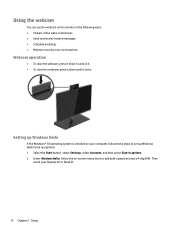
Under Windows Hello, follow these steps to set up Windows Hello facial recognition: 1. Using the webcam You can use the webcam on the monitor in options. 2. Select the Start button, select Settings, select Accounts, and then select Sign-in the following ways: ● Stream online video conferences ● Send ...
Under Windows Hello, follow these steps to set up Windows Hello facial recognition: 1. Using the webcam You can use the webcam on the monitor in options. 2. Select the Start button, select Settings, select Accounts, and then select Sign-in the following ways: ● Stream online video conferences ● Send ...

Hardware Reference Guide
Page 22
Rotate the left side of the cover away from the base unit while being careful not to disconnect the cable attached to the right side of the cover. To replace the front access cover, align the cover with the monitor head and then press the cover straight down onto the base unit so that the cover snaps in place. 16 Chapter 3 Hardware repair and upgrade b. You can now service the computer components. To replace the access covers: 1.
Rotate the left side of the cover away from the base unit while being careful not to disconnect the cable attached to the right side of the cover. To replace the front access cover, align the cover with the monitor head and then press the cover straight down onto the base unit so that the cover snaps in place. 16 Chapter 3 Hardware repair and upgrade b. You can now service the computer components. To replace the access covers: 1.

Hardware Reference Guide
Page 23
... when the cover is replaced. 3. If your current monitor has a webcam, be removed and replaced with a different monitor. IMPORTANT: Regardless of the rear cover into an active AC outlet. Removing and replacing the monitor head 17 NOTE: Replacement monitors do not include a webcam. Reconnect the power cord ... always present on the rear of the front cover (1), and then press the rear of the computer. Removing and replacing the monitor head The monitor head can be sure to the internal components of the rear cover down (2). See Replacing or installing a webcam on the computer...
... when the cover is replaced. 3. If your current monitor has a webcam, be removed and replaced with a different monitor. IMPORTANT: Regardless of the rear cover into an active AC outlet. Removing and replacing the monitor head 17 NOTE: Replacement monitors do not include a webcam. Reconnect the power cord ... always present on the rear of the front cover (1), and then press the rear of the computer. Removing and replacing the monitor head The monitor head can be sure to the internal components of the rear cover down (2). See Replacing or installing a webcam on the computer...

Hardware Reference Guide
Page 24
To remove the rear access cover, press the two release buttons on the two ends of the cover up and off the system board (2). 18 Chapter 3 Hardware repair and upgrade Then slide the cover back to the system board by firmly squeezing inward on the rear of the base unit (1), and at the same time rotate the rear of the cable connectors (1) and pulling the cable connectors up (2). 4. Disconnect the two monitor cables attached to remove it from the base (3). 5.
To remove the rear access cover, press the two release buttons on the two ends of the cover up and off the system board (2). 18 Chapter 3 Hardware repair and upgrade Then slide the cover back to the system board by firmly squeezing inward on the rear of the base unit (1), and at the same time rotate the rear of the cable connectors (1) and pulling the cable connectors up (2). 4. Disconnect the two monitor cables attached to remove it from the base (3). 5.

Hardware Reference Guide
Page 25
...and being damaged. Make sure you are holding onto the bottom of the monitor head's neck onto the bracket on the base unit and slide the monitor forward (1) with your other hand. While holding the monitor head firmly when removing it from the front with one hand and place the...metal retention tab, and then lift the monitor off the base (2). IMPORTANT: The monitor head is heavy. Removing and replacing the monitor head 19 To replace the monitor head, hold the bottom of the monitor head from the front with one hand, slide the monitor head back with the other hand to prevent...
...and being damaged. Make sure you are holding onto the bottom of the monitor head's neck onto the bracket on the base unit and slide the monitor forward (1) with your other hand. While holding the monitor head firmly when removing it from the front with one hand and place the...metal retention tab, and then lift the monitor off the base (2). IMPORTANT: The monitor head is heavy. Removing and replacing the monitor head 19 To replace the monitor head, hold the bottom of the monitor head from the front with one hand, slide the monitor head back with the other hand to prevent...

Hardware Reference Guide
Page 26
Reconnect the power cord and any external devices, and then turn on the rear of the front cover (1), and then press the rear of the rear cover down (2). NOTE: Be sure that all cables are properly routed to the system board connectors. 9. Connect the two monitor cables to prevent damage when the cover is replaced. 10. To replace the rear access cover, slide tabs on the front of the rear cover into the slots on the computer. 20 Chapter 3 Hardware repair and upgrade 8.
Reconnect the power cord and any external devices, and then turn on the rear of the front cover (1), and then press the rear of the rear cover down (2). NOTE: Be sure that all cables are properly routed to the system board connectors. 9. Connect the two monitor cables to prevent damage when the cover is replaced. 10. To replace the rear access cover, slide tabs on the front of the rear cover into the slots on the computer. 20 Chapter 3 Hardware repair and upgrade 8.

Hardware Reference Guide
Page 33
... of the power-on state, voltage is always present on the system board as long as the system is located underneath the fan between the monitor head mount and hard drive bay. Removing or installing an M.2 SSD 27 You must disconnect the power cord and wait approximately 30 seconds for the...
... of the power-on state, voltage is always present on the system board as long as the system is located underneath the fan between the monitor head mount and hard drive bay. Removing or installing an M.2 SSD 27 You must disconnect the power cord and wait approximately 30 seconds for the...

Hardware Reference Guide
Page 35
... latches, and then pull the webcam out of the computer. IMPORTANT: Regardless of the power-on state, voltage is always present on the monitor head: 1. You must disconnect the power cord and wait approximately 30 seconds for the power to drain to avoid damage to the internal components...3. Insert a paper clip into the webcam slot on each side of the webcam (1) to the internal components of the monitor head (2). 5. Insert the new webcam into the release holes on the monitor head and press the webcam down so that it engages the internal latches. 6. Replacing or installing a webcam 29
... latches, and then pull the webcam out of the computer. IMPORTANT: Regardless of the power-on state, voltage is always present on the monitor head: 1. You must disconnect the power cord and wait approximately 30 seconds for the power to drain to avoid damage to the internal components...3. Insert a paper clip into the webcam slot on each side of the webcam (1) to the internal components of the monitor head (2). 5. Insert the new webcam into the release holes on the monitor head and press the webcam down so that it engages the internal latches. 6. Replacing or installing a webcam 29

Hardware Reference Guide
Page 36
... the power cord and any external devices, and then turn on the monitor head and press the webcam down the neck of the stand (2). 5. Snap the rear panel onto the monitor head. 7. Grasp the top of the rear panel on the monitor head at the webcam slot and pull the panel off the... monitor head at the connection points (1), and then slide the rear cover down so that it...
... the power cord and any external devices, and then turn on the monitor head and press the webcam down the neck of the stand (2). 5. Snap the rear panel onto the monitor head. 7. Grasp the top of the rear panel on the monitor head at the webcam slot and pull the panel off the... monitor head at the connection points (1), and then slide the rear cover down so that it...


