User Manual
Page 6
... Remote Switch Management 3-5 Starting a Telnet Session 3-5 Starting a Web Browser Session 3-5 Replacing Components Replacing the Fan Tray 4-1 Replacing the 10-GbE Ports 4-3 Replacing the Battery 4-4 Installing a New Battery 4-4 Troubleshooting Basic Troubleshooting Tips 5-1 iv 7.
... Remote Switch Management 3-5 Starting a Telnet Session 3-5 Starting a Web Browser Session 3-5 Replacing Components Replacing the Fan Tray 4-1 Replacing the 10-GbE Ports 4-3 Replacing the Battery 4-4 Installing a New Battery 4-4 Troubleshooting Basic Troubleshooting Tips 5-1 iv 7.
User Manual
Page 7
...-Pair Cabling 5-11 Testing Switch-to-Device Network Communications 5-11 Testing End-to-End Network Communications 5-11 Restoring the Factory Default Configuration 5-12 Downloading New Switch Software 5-13 HP Customer Support Services 5-14 Before Calling Support 5-14 Specifications Physical A-1 Electrical A-1 Environmental A-1 Acoustic A-2 Connectors A-2 Safety A-2 Lasers A-3 Optical Power Specifications A-4 ProCurve 10-GbE X2...
...-Pair Cabling 5-11 Testing Switch-to-Device Network Communications 5-11 Testing End-to-End Network Communications 5-11 Restoring the Factory Default Configuration 5-12 Downloading New Switch Software 5-13 HP Customer Support Services 5-14 Before Calling Support 5-14 Specifications Physical A-1 Electrical A-1 Environmental A-1 Acoustic A-2 Connectors A-2 Safety A-2 Lasers A-3 Optical Power Specifications A-4 ProCurve 10-GbE X2...

User Manual
Page 8
... C-1 Informations concernant la sécurit C-2 Hinweise zur Sicherheit C-3 Considerazioni sulla sicurezza C-4 Consideraciones sobre seguridad C-5 Safety Information (Japan C-6 Safety Information (China C-7 EMC Regulatory Statements C-8 U.S.A C-8 Canada C-8 Australia/New Zealand C-8 Japan C-8 Korea C-9 Taiwan C-9 European Community C-10 Recycle Statements Waste Electrical and Electronic Equipment (WEEE) Statements D-1 Index vi
... C-1 Informations concernant la sécurit C-2 Hinweise zur Sicherheit C-3 Considerazioni sulla sicurezza C-4 Consideraciones sobre seguridad C-5 Safety Information (Japan C-6 Safety Information (China C-7 EMC Regulatory Statements C-8 U.S.A C-8 Canada C-8 Australia/New Zealand C-8 Japan C-8 Korea C-9 Taiwan C-9 European Community C-10 Recycle Statements Waste Electrical and Electronic Equipment (WEEE) Statements D-1 Index vi

User Manual
Page 20
... Manager Plus, is on the ProCurve Web site, www.procurve.com. (See page 5-1 for details.) ■ Download of new switch software for product enhancements. 1-12 It adds many advanced features to manage your new switch. For a description, see the Management and Configuration Guide, which is available. This product is included with your...
... Manager Plus, is on the ProCurve Web site, www.procurve.com. (See page 5-1 for details.) ■ Download of new switch software for product enhancements. 1-12 It adds many advanced features to manage your new switch. For a description, see the Management and Configuration Guide, which is available. This product is included with your...
User Manual
Page 22
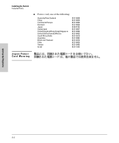
Installing the Switch Included Parts ■ Power cord, one of the following: Australia/New Zealand China Continental Europe Denmark Japan Switzerland United Kingdom/Hong Kong/Singapore United States/Canada/Mexico South Africa/India Argentina Brazil and Thailand Chile Taiwan Israel 8121-0828 8121-0829 8121-0823 8121-0826 8120-4753 8121-0827 8121-0824 8121-0822 8121-0919 8121-0883 8121-0673 8121-0825 8121-0965 8121-1063 Japan Power Cord Warning Installing the Switch 2-2
Installing the Switch Included Parts ■ Power cord, one of the following: Australia/New Zealand China Continental Europe Denmark Japan Switzerland United Kingdom/Hong Kong/Singapore United States/Canada/Mexico South Africa/India Argentina Brazil and Thailand Chile Taiwan Israel 8121-0828 8121-0829 8121-0823 8121-0826 8120-4753 8121-0827 8121-0824 8121-0822 8121-0919 8121-0883 8121-0673 8121-0825 8121-0965 8121-1063 Japan Power Cord Warning Installing the Switch 2-2
User Manual
Page 38
..., easy to use a VT-100 terminal, and configure either out-of-band console access or through the Console Port and one in troubleshooting ■ download new software to the switch ■ add passwords to control access to the switch from the console, web browser interface, and network management stations The console...
..., easy to use a VT-100 terminal, and configure either out-of-band console access or through the Console Port and one in troubleshooting ■ download new software to the switch ■ add passwords to control access to the switch from the console, web browser interface, and network management stations The console...
User Manual
Page 60
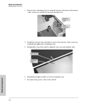
Reinstall the top of the switch. Reinstall and tighten all the screws securing the top. 7. Install the new fan tray assembly, reconnect the fan tray cable connector, reinstall and tighten the retaining screw. 5. Remove the retaining screw securing the fan tray, disconnect the fan tray cable connector, and lift the fan tray assembly out. Top Cover Pin Alignment Hole 6. Reconnect the power cable to the switch. 4-2 Replacing Components Align the top cover pin with the hole. Replacing Components Replacing the Fan Tray 3. Retaining Screw Cable Connector 4.
Reinstall the top of the switch. Reinstall and tighten all the screws securing the top. 7. Install the new fan tray assembly, reconnect the fan tray cable connector, reinstall and tighten the retaining screw. 5. Remove the retaining screw securing the fan tray, disconnect the fan tray cable connector, and lift the fan tray assembly out. Top Cover Pin Alignment Hole 6. Reconnect the power cable to the switch. 4-2 Replacing Components Align the top cover pin with the hole. Replacing Components Replacing the Fan Tray 3. Retaining Screw Cable Connector 4.
User Manual
Page 61
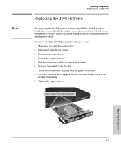
Make sure the switch is not supported. Pull the extractors handles to seat the module completely. 9. Remove any transceivers. 4. Insert the new module aligning with guides Replacing Components 4-3 Tighten the captive screws. Align the edges of the board with the guides in the slot. 8. If the 10-...
Make sure the switch is not supported. Pull the extractors handles to seat the module completely. 9. Remove any transceivers. 4. Insert the new module aligning with guides Replacing Components 4-3 Tighten the captive screws. Align the edges of the board with the guides in the slot. 8. If the 10-...
User Manual
Page 62
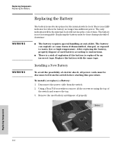
... indication will be disconnected from the switch. 2. Replace the battery with the same type. To install (or replace) a Battery: 1. There is not hot swappable. Installing a New Battery To avoid the possibility of electric shock, all the screws securing the top of properly. Replacing Components Replacing the Battery WARNING WARNING Replacing the...
... indication will be disconnected from the switch. 2. Replace the battery with the same type. To install (or replace) a Battery: 1. There is not hot swappable. Installing a New Battery To avoid the possibility of electric shock, all the screws securing the top of properly. Replacing Components Replacing the Battery WARNING WARNING Replacing the...

User Manual
Page 63
... the top. 7. Reconnect the power cable to replace with the lettering and the plus "+" sign facing up. Replacing Components 4-5 Replacing Components Replacing the Battery 4. Insert a new battery with the same type of the switch. Be sure to the switch. Reinstall the top of battery. 5. Remplacer uniquement avec une batterie du mê...
... the top. 7. Reconnect the power cable to replace with the lettering and the plus "+" sign facing up. Replacing Components 4-5 Replacing Components Replacing the Battery 4. Insert a new battery with the same type of the switch. Be sure to the switch. Reinstall the top of battery. 5. Remplacer uniquement avec une batterie du mê...
User Manual
Page 65
... with the LEDs (page 5-4) ■ Proactive Networking Tools (page 5-9) ■ Hardware Diagnostic Tests (page 5-10) ■ Restoring the Factory Default Configuration (page 5-12) ■ Downloading New Switch Software (page 5-13) ■ HP Customer Support Services (page 5-14) Basic Troubleshooting Tips Most problems are configured as "Auto".
... with the LEDs (page 5-4) ■ Proactive Networking Tools (page 5-9) ■ Hardware Diagnostic Tests (page 5-10) ■ Restoring the Factory Default Configuration (page 5-12) ■ Downloading New Switch Software (page 5-13) ■ HP Customer Support Services (page 5-14) Basic Troubleshooting Tips Most problems are configured as "Auto".
User Manual
Page 66
...the switch has a fixed configuration at the end of half duplex. The result will not connect correctly to the switch. Use a new correctly-wired cable or compare your cable to connect at any two end nodes, there should be high error rates and very inefficient ...the switch are configured to auto negotiate, or are configured this way (in your network topology contains no longer experience the problems, the new topology is important to provide some topology configuration guidelines can seriously impair network performance. A category 5 cable tester is a recommended tool ...
...the switch has a fixed configuration at the end of half duplex. The result will not connect correctly to the switch. Use a new correctly-wired cable or compare your cable to connect at any two end nodes, there should be high error rates and very inefficient ...the switch are configured to auto negotiate, or are configured this way (in your network topology contains no longer experience the problems, the new topology is important to provide some topology configuration guidelines can seriously impair network performance. A category 5 cable tester is a recommended tool ...

User Manual
Page 77
For more information, see the Management and Configuration Guide, which is on the ProCurve Web site, www.procurve.com. 5-13 Troubleshooting Troubleshooting Downloading New Switch Software Downloading New Switch Software When product enhancements occur for the switch, new software can be downloaded to the switch through several methods, for details.) The new switch software would be available on the ProCurve Web site, www.procurve.com. (See page 5-1 for product enhancements and new features.
For more information, see the Management and Configuration Guide, which is on the ProCurve Web site, www.procurve.com. 5-13 Troubleshooting Troubleshooting Downloading New Switch Software Downloading New Switch Software When product enhancements occur for the switch, new software can be downloaded to the switch through several methods, for details.) The new switch software would be available on the ProCurve Web site, www.procurve.com. (See page 5-1 for product enhancements and new features.
User Manual
Page 100
...in a commercial environment. Japan VCCI Class A C-8 Safety and EMC Regulatory Statements Operation of the FCC Rules. Australia/New Zealand This product complies with Class A Canadian EMC requirements. These limits are designed to radio communications. Canada This product complies with Australia.../New Zealand EMC Class A requirements. This equipment generates, uses, and can radiate radio frequency energy and, if not installed ...
...in a commercial environment. Japan VCCI Class A C-8 Safety and EMC Regulatory Statements Operation of the FCC Rules. Australia/New Zealand This product complies with Class A Canadian EMC requirements. These limits are designed to radio communications. Canada This product complies with Australia.../New Zealand EMC Class A requirements. This equipment generates, uses, and can radiate radio frequency energy and, if not installed ...
User Manual
Page 108
... checking the console messages ... 5-10 checking the LEDs ... 5-10 end-to-end connectivity ... 5-11 testing the switch only ... 5-10 testing twisted-pair cabling ... 5-11 downloading new switch software ... 5-13 dual-personality ports location on switch ... 1-3 cross-over cable pin-out ... B-7 D deleting passwords ... 1-7 description back of switch ... 1-9 front of -band ... 2-18 serial...
... checking the console messages ... 5-10 checking the LEDs ... 5-10 end-to-end connectivity ... 5-11 testing the switch only ... 5-10 testing twisted-pair cabling ... 5-11 downloading new switch software ... 5-13 dual-personality ports location on switch ... 1-3 cross-over cable pin-out ... B-7 D deleting passwords ... 1-7 description back of switch ... 1-9 front of -band ... 2-18 serial...

User Manual
Page 111
... installation ... 2-11 Switch Setup screen configuring a subnet mask ... 3-3 configuring an IP address ... 3-3 field descriptions ... 3-3 switch setup screen ... 3-2 T telnet access to a power source ... 2-15 description ... 1-1 downloading new software ... 5-13 electrical specifications ... Index resetting the switch factory default reset ... 5-12 location of reset button ... 1-7 troubleshooting procedure ... 5-10 RPS connections sample topology ... 2-23 RPS...
... installation ... 2-11 Switch Setup screen configuring a subnet mask ... 3-3 configuring an IP address ... 3-3 field descriptions ... 3-3 switch setup screen ... 3-2 T telnet access to a power source ... 2-15 description ... 1-1 downloading new software ... 5-13 electrical specifications ... Index resetting the switch factory default reset ... 5-12 location of reset button ... 1-7 troubleshooting procedure ... 5-10 RPS connections sample topology ... 2-23 RPS...