User Manual
Page 4
...proprietary information, which is protected by Hewlett-Packard. HP shall not be liable for HP products and services are US registered trademarks of its software on equipment that is subject to your Hewlett-Packard products and replacement parts can be photocopied, reproduced, or translated into ... warranties for technical or editorial errors or omissions contained herein. Publication Number 5991-4737 September 2006 Applicable Products ProCurve Switch 2900-24G (J9049A) ProCurve Switch 2900-48G (J9050A) ProCurve 10-GbE X2 SR-SC Xcvr (J8436A) ProCurve 10-GbE X2 LR-SC Xcvr (...
...proprietary information, which is protected by Hewlett-Packard. HP shall not be liable for HP products and services are US registered trademarks of its software on equipment that is subject to your Hewlett-Packard products and replacement parts can be photocopied, reproduced, or translated into ... warranties for technical or editorial errors or omissions contained herein. Publication Number 5991-4737 September 2006 Applicable Products ProCurve Switch 2900-24G (J9049A) ProCurve Switch 2900-48G (J9050A) ProCurve 10-GbE X2 SR-SC Xcvr (J8436A) ProCurve 10-GbE X2 LR-SC Xcvr (...
User Manual
Page 6
... to Go From Here 3-4 To Recover from a Lost Manager Password 3-4 Using the IP Address for Remote Switch Management 3-5 Starting a Telnet Session 3-5 Starting a Web Browser Session 3-5 Replacing Components Replacing the Fan Tray 4-1 Replacing the 10-GbE Ports 4-3 Replacing the Battery 4-4 Installing a New Battery 4-4 Troubleshooting Basic Troubleshooting Tips 5-1 iv
... to Go From Here 3-4 To Recover from a Lost Manager Password 3-4 Using the IP Address for Remote Switch Management 3-5 Starting a Telnet Session 3-5 Starting a Web Browser Session 3-5 Replacing Components Replacing the Fan Tray 4-1 Replacing the 10-GbE Ports 4-3 Replacing the Battery 4-4 Installing a New Battery 4-4 Troubleshooting Basic Troubleshooting Tips 5-1 iv

User Manual
Page 16
... indicates overall status of the switch. Otherwise, the port may have no active network cable connected, or is required the switch be powered down before replacing the 10-GbE ports. 1-8 There are displaying link information: • if the port LED is on the back of the 10-GbE ports. FDx and...
... indicates overall status of the switch. Otherwise, the port may have no active network cable connected, or is required the switch be powered down before replacing the 10-GbE ports. 1-8 There are displaying link information: • if the port LED is on the back of the 10-GbE ports. FDx and...
User Manual
Page 59
... components. When a fan fails the Fan Status LED on the switch will blink simultaneously with the switch Fault LED. Replacing Components 4-1 Disconnect the power cables from the switch before starting this case, the entire fan tray needs to...procedure. To avoid the possibility of electric shock, all power cords must be replaced. Using a Torx T-10 screwdriver remove all static precautions when replacing components. Individual fans cannot be done during scheduled downtime. 4 Replacing Components This chapter shows you how to static discharge. Caution The ProCurve 2900 ...
... components. When a fan fails the Fan Status LED on the switch will blink simultaneously with the switch Fault LED. Replacing Components 4-1 Disconnect the power cables from the switch before starting this case, the entire fan tray needs to...procedure. To avoid the possibility of electric shock, all power cords must be replaced. Using a Torx T-10 screwdriver remove all static precautions when replacing components. Individual fans cannot be done during scheduled downtime. 4 Replacing Components This chapter shows you how to static discharge. Caution The ProCurve 2900 ...
User Manual
Page 60
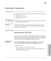
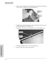
Install the new fan tray assembly, reconnect the fan tray cable connector, reinstall and tighten the retaining screw. 5. Reinstall the top of the switch. Retaining Screw Cable Connector 4. Top Cover Pin Alignment Hole 6. Replacing Components Replacing the Fan Tray 3. Reinstall and tighten all the screws securing the top. 7. Reconnect the power cable to the switch. 4-2 Replacing Components Remove the retaining screw securing the fan tray, disconnect the fan tray cable connector, and lift the fan tray assembly out. Align the top cover pin with the hole.
Install the new fan tray assembly, reconnect the fan tray cable connector, reinstall and tighten the retaining screw. 5. Reinstall the top of the switch. Retaining Screw Cable Connector 4. Top Cover Pin Alignment Hole 6. Replacing Components Replacing the Fan Tray 3. Reinstall and tighten all the screws securing the top. 7. Reconnect the power cable to the switch. 4-2 Replacing Components Remove the retaining screw securing the fan tray, disconnect the fan tray cable connector, and lift the fan tray assembly out. Align the top cover pin with the hole.
User Manual
Page 61
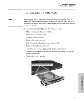
... scheduled downtime with the switch powered on, a switch reset will occur. Remove any transceivers. 4. Insert the new module aligning with guides Replacing Components 4-3 Note Replacing Components Replacing the 10-GbE Ports Replacing the 10-GbE Ports Hot swapping the 10-GbE ports is powered off . If the 10-GbE ports are installed or removed...
... scheduled downtime with the switch powered on, a switch reset will occur. Remove any transceivers. 4. Insert the new module aligning with guides Replacing Components 4-3 Note Replacing Components Replacing the 10-GbE Ports Replacing the 10-GbE Ports Hot swapping the 10-GbE ports is powered off . If the 10-GbE ports are installed or removed...
User Manual
Page 62
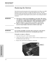
... if disassembled, charged, or exposed to water, fire or high temperature. There is no longer has sufficient power. Battery Replacing Components 4-4 After replacing the battery, properly dispose of used battery and dispose of the switch and remove the top. 3. Disconnect the power cable... internal clock will not keep time for when the battery no LED indicator for the internal switch clock. Replacing Components Replacing the Battery WARNING WARNING Replacing the Battery The battery is used to keep the correct time. The only indication will be done during scheduled...
... if disassembled, charged, or exposed to water, fire or high temperature. There is no longer has sufficient power. Battery Replacing Components 4-4 After replacing the battery, properly dispose of used battery and dispose of the switch and remove the top. 3. Disconnect the power cable... internal clock will not keep time for when the battery no LED indicator for the internal switch clock. Replacing Components Replacing the Battery WARNING WARNING Replacing the Battery The battery is used to keep the correct time. The only indication will be done during scheduled...

User Manual
Page 63
... the plus "+" sign facing up. Reinstall the top of battery. 5. Reinstall and tighten all the screws securing the top. 7. Be sure to the switch. Replacing Components 4-5 Replacing Components Replacing the Battery 4. ll y a danger d'explosion s'il y a remplacement incorrect de la batterie. Remplacer uniquement avec une batterie du même type ou d'un type é...
... the plus "+" sign facing up. Reinstall the top of battery. 5. Reinstall and tighten all the screws securing the top. 7. Be sure to the switch. Replacing Components 4-5 Replacing Components Replacing the Battery 4. ll y a danger d'explosion s'il y a remplacement incorrect de la batterie. Remplacer uniquement avec une batterie du même type ou d'un type é...

User Manual
Page 69
... configure it from ProCurve to get assistance. source, or the switch's power supply may have both of the Try disconnecting power from HP has occurred. The switch will stay on indefinitely. ➌ The switch has 1. Call your ProCurve authorized LAN dealer, or use ...the Customer Support/Warranty booklet for more information. If the fault indication reoccurs, attach a console to get assistance. Messages should be replaced. If necessary to resolve the problem, contact your ProCurve authorized LAN dealer, or use the electronic support services from ProCurve to the...
... configure it from ProCurve to get assistance. source, or the switch's power supply may have both of the Try disconnecting power from HP has occurred. The switch will stay on indefinitely. ➌ The switch has 1. Call your ProCurve authorized LAN dealer, or use ...the Customer Support/Warranty booklet for more information. If the fault indication reoccurs, attach a console to get assistance. Messages should be replaced. If necessary to resolve the problem, contact your ProCurve authorized LAN dealer, or use the electronic support services from ProCurve to the...

User Manual
Page 70
... switch port may have to power off the switch. To verify the port has failed, try removing and reinstalling the mini-GBIC without having to replace the mini-GBIC. The supported miniGBICs are listed on page 2-1. Call your ProCurve authorized LAN dealer, or use the electronic support services is on the...
... switch port may have to power off the switch. To verify the port has failed, try removing and reinstalling the mini-GBIC without having to replace the mini-GBIC. The supported miniGBICs are listed on page 2-1. Call your ProCurve authorized LAN dealer, or use the electronic support services is on the...
User Manual
Page 93
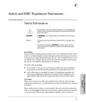
... information about the product. However, they are safety class I products and have a safety switch for when the cover is marked with caution. Whenever it is replaced. For LAN cable grounding: ■ If your LAN covers an area served by service-trained personnel. WARNING Caution Documentation reference symbol.
... information about the product. However, they are safety class I products and have a safety switch for when the cover is marked with caution. Whenever it is replaced. For LAN cable grounding: ■ If your LAN covers an area served by service-trained personnel. WARNING Caution Documentation reference symbol.
User Manual
Page 107
...... B-6, B-8 switch-to MDI connections ... B-7 MDI-X to -switch or hub connection ... B-7 pin-outs ... B-7 cables, twisted-pair HP Auto-MDIX feature ... B-6, B-8 HP Auto-MDIX feature ... B-6, B-8 MDI-X to -computer connection ... B-6, B-8 switch-to MDI-X connections ... B-5 wiring rules ... B-2 1000Base... ... 3-2 subnet mask ... 3-3 switch setup screen ... 3-2 basic troubleshooting tips ... 5-1 battery replacing battery ... 4-4 blinking LEDs error indications ... 5-4 Bootp automatic switch configuration ... 3-2 for direct console connection ... 2-19 cables, twisted pair category 3, ...
...... B-6, B-8 switch-to MDI connections ... B-7 MDI-X to -switch or hub connection ... B-7 pin-outs ... B-7 cables, twisted-pair HP Auto-MDIX feature ... B-6, B-8 HP Auto-MDIX feature ... B-6, B-8 MDI-X to -computer connection ... B-6, B-8 switch-to MDI-X connections ... B-5 wiring rules ... B-2 1000Base... ... 3-2 subnet mask ... 3-3 switch setup screen ... 3-2 basic troubleshooting tips ... 5-1 battery replacing battery ... 4-4 blinking LEDs error indications ... 5-4 Bootp automatic switch configuration ... 3-2 for direct console connection ... 2-19 cables, twisted pair category 3, ...
User Manual
Page 108
C-8 environmental specifications, switch ... B-2 1000Base-LH ... B-2 1000Base-SX ... A-1 F factory default configuration, restoring ... 1-7, 5-12 Fan Status LED ... 2-22 fan Status LED ... 1-5 fans replacing fan trays ... 4-1 Fault LED ... 2-22 behavior during troubleshooting ... 5-10 displaying the CLI prompt ... 2-19 features ... 2-18 how to connect in -band access ... 2-18 diagnostic tests ... 5-...
C-8 environmental specifications, switch ... B-2 1000Base-LH ... B-2 1000Base-SX ... A-1 F factory default configuration, restoring ... 1-7, 5-12 Fan Status LED ... 2-22 fan Status LED ... 1-5 fans replacing fan trays ... 4-1 Fault LED ... 2-22 behavior during troubleshooting ... 5-10 displaying the CLI prompt ... 2-19 features ... 2-18 how to connect in -band access ... 2-18 diagnostic tests ... 5-...

User Manual
Page 110
...1000Base-LX connections ... 2-6 1000Base-SX connections ... 2-6 1000Base-T connections ... 2-5 fiber-optic, specifications ... C-8 replacing components management module battery ... 4-4 replacing hardware fans ... 4-1 Reset button location on switch ... 1-3 restoring factory default configuration ... 5-12 reset button ...description ... 1-7 location on switch ... 1-3 power source connecting the switch to ... 2-16 console ... 2-18 HP Auto-MDIX feature ... B-2 HP...
...1000Base-LX connections ... 2-6 1000Base-SX connections ... 2-6 1000Base-T connections ... 2-5 fiber-optic, specifications ... C-8 replacing components management module battery ... 4-4 replacing hardware fans ... 4-1 Reset button location on switch ... 1-3 restoring factory default configuration ... 5-12 reset button ...description ... 1-7 location on switch ... 1-3 power source connecting the switch to ... 2-16 console ... 2-18 HP Auto-MDIX feature ... B-2 HP...
