Start Here
Page 9
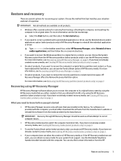
... use the Reinstall drivers and/or applications option (select products only) of HP Recovery Manager to reinstall the individual application or driver. ▲ Type recovery in the taskbar search box, select HP Recovery Manager, select Reinstall drivers and/or applications, and then follow the on-screen instructions. ● If you want to recover the computer's original factory partition and content, or if you have not already created recovery media, see Removing the HP Recovery partition...
... use the Reinstall drivers and/or applications option (select products only) of HP Recovery Manager to reinstall the individual application or driver. ▲ Type recovery in the taskbar search box, select HP Recovery Manager, select Reinstall drivers and/or applications, and then follow the on-screen instructions. ● If you want to recover the computer's original factory partition and content, or if you have not already created recovery media, see Removing the HP Recovery partition...
Start Here
Page 11
... HP Recovery Manager. 2. Restore and recovery 7 Removing the HP Recovery partition (select products only) HP Recovery Manager software allows you want to an optical drive or a USB flash drive. To change the boot order: IMPORTANT: For a tablet with keyboards attached: ▲ Turn on or restart the tablet, and then quickly hold down the volume down the Windows button; Access BIOS: For computers or tablets with a detachable keyboard, connect the keyboard to free up hard drive space. Insert the HP Recovery media. 2. So before you can change the computer boot order...
... HP Recovery Manager. 2. Restore and recovery 7 Removing the HP Recovery partition (select products only) HP Recovery Manager software allows you want to an optical drive or a USB flash drive. To change the boot order: IMPORTANT: For a tablet with keyboards attached: ▲ Turn on or restart the tablet, and then quickly hold down the volume down the Windows button; Access BIOS: For computers or tablets with a detachable keyboard, connect the keyboard to free up hard drive space. Insert the HP Recovery media. 2. So before you can change the computer boot order...

Maintenance and Service Guide
Page 17
... the Start screen, type support, and then select the HP Support Assistant app. Each USB 3.0 port connects an optional USB device, such as a highdefinition television, any compatible digital or audio component, or a high-speed HDMI device. This jack does not support optional microphone-only devices. To access this guide, from being mishandled or stolen. To reduce the risk of personal injury, adjust the volume before putting on and off during routine operation. NOTE: The computer fan starts...
... the Start screen, type support, and then select the HP Support Assistant app. Each USB 3.0 port connects an optional USB device, such as a highdefinition television, any compatible digital or audio component, or a high-speed HDMI device. This jack does not support optional microphone-only devices. To access this guide, from being mishandled or stolen. To reduce the risk of personal injury, adjust the volume before putting on and off during routine operation. NOTE: The computer fan starts...
Maintenance and Service Guide
Page 32
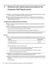
... operating system. 2. Disconnect all external devices from HP. To prevent loss of each secured by unplugging the power cord from the computer. 3. NOTE: HP continually improves and changes product parts. See Locating the model number, serial number, product number, and warranty information on page 12 for Customer Self-Repair parts This chapter provides removal and replacement procedures for Customer Self-Repair parts. Make special note of information, save your computer. CAUTION: Removing a battery...
... operating system. 2. Disconnect all external devices from HP. To prevent loss of each secured by unplugging the power cord from the computer. 3. NOTE: HP continually improves and changes product parts. See Locating the model number, serial number, product number, and warranty information on page 12 for Customer Self-Repair parts This chapter provides removal and replacement procedures for Customer Self-Repair parts. Make special note of information, save your computer. CAUTION: Removing a battery...
Maintenance and Service Guide
Page 34
... in Hibernation, turn the computer on -screen instructions. Remove the bottom cover: 1. Disconnect all external devices from the computer. 4. NOTE: HP continually improves and changes product parts. See Locating the model number, serial number, product number, and warranty information on page 24). 6 Removal and replacement procedures for Authorized Service Provider parts CAUTION: Components described in this chapter should only be removed, replaced, and/or loosened when servicing the Authorized Service Provider only parts. Remove the following...
... in Hibernation, turn the computer on -screen instructions. Remove the bottom cover: 1. Disconnect all external devices from the computer. 4. NOTE: HP continually improves and changes product parts. See Locating the model number, serial number, product number, and warranty information on page 24). 6 Removal and replacement procedures for Authorized Service Provider parts CAUTION: Components described in this chapter should only be removed, replaced, and/or loosened when servicing the Authorized Service Provider only parts. Remove the following...
Maintenance and Service Guide
Page 43
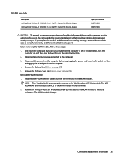
... message, remove the module to restore device functionality, and then contact technical support. NOTE: The #1/white WLAN antenna cable connects to the WLAN module #1/Aux terminal. 2. Shut down through the operating system. 2. The #2/ black WLAN antenna cable connects to the WLAN module #1/Main terminal. Disconnect all external devices connected to the base enclosure. (The WLAN module tilts up.) Component replacement procedures 35 Remove the battery (see Bottom cover on the WLAN module. Remove the...
... message, remove the module to restore device functionality, and then contact technical support. NOTE: The #1/white WLAN antenna cable connects to the WLAN module #1/Aux terminal. 2. Shut down through the operating system. 2. The #2/ black WLAN antenna cable connects to the WLAN module #1/Main terminal. Disconnect all external devices connected to the base enclosure. (The WLAN module tilts up.) Component replacement procedures 35 Remove the battery (see Bottom cover on the WLAN module. Remove the...

Maintenance and Service Guide
Page 71
...; Turn on the system (such as disk drives, display, keyboard, mouse, and printer). Press the power button in Computer Setup. NOTE: Use extreme care when making changes in combination with Computer Setup only if USB legacy support is displayed, and then tap F10 to select the item. Computer Setup includes settings for the types of devices installed, the startup sequence of the computer, and the amount of the screen, or use a pointing device to enter Computer Setup.
...; Turn on the system (such as disk drives, display, keyboard, mouse, and printer). Press the power button in Computer Setup. NOTE: Use extreme care when making changes in combination with Computer Setup only if USB legacy support is displayed, and then tap F10 to select the item. Computer Setup includes settings for the types of devices installed, the startup sequence of the computer, and the amount of the screen, or use a pointing device to enter Computer Setup.
Maintenance and Service Guide
Page 73
... download or install a BIOS update while the computer is downloaded. At the download area, follow these instructions: Do not disconnect power on -screen instructions. - Some download packages contain a file named Readme.txt, which contains information regarding installing and troubleshooting the file. Select Main, select Ignore Changes and Exit, and then press enter. See Starting Computer Setup on page 65. Do not insert, remove, connect, or disconnect any device, cable, or cord. 1. Type support...
... download or install a BIOS update while the computer is downloaded. At the download area, follow these instructions: Do not disconnect power on -screen instructions. - Some download packages contain a file named Readme.txt, which contains information regarding installing and troubleshooting the file. Select Main, select Ignore Changes and Exit, and then press enter. See Starting Computer Setup on page 65. Do not insert, remove, connect, or disconnect any device, cable, or cord. 1. Type support...

Maintenance and Service Guide
Page 74
... the update. 4. Press the power button in Computer Setup: 1. NOTE: If you connect your computer to a network, consult the network administrator before installing any related liabilities. Select a boot device, then press enter. The BIOS installation begins. 5. TPM BIOS settings (select products only) IMPORTANT: Before enabling Trusted Platform Module (TPM) functionality on -screen instructions. 66 Chapter 7 Computer Setup (BIOS), TPM, and HP Sure Start - Changing the boot order using the f9 prompt To dynamically choose a boot device for the current startup sequence...
... the update. 4. Press the power button in Computer Setup: 1. NOTE: If you connect your computer to a network, consult the network administrator before installing any related liabilities. Select a boot device, then press enter. The BIOS installation begins. 5. TPM BIOS settings (select products only) IMPORTANT: Before enabling Trusted Platform Module (TPM) functionality on -screen instructions. 66 Chapter 7 Computer Setup (BIOS), TPM, and HP Sure Start - Changing the boot order using the f9 prompt To dynamically choose a boot device for the current startup sequence...

Maintenance and Service Guide
Page 76
... scroll up and down, click the up arrow key or the down arrow in the upper-right corner of the screen, and then follow these steps: 1. To start Computer Setup, follow the on the system (such as disk drives, display, keyboard, mouse, and printer). Windows 8 Using Computer Setup Computer Setup, or Basic Input/Output System (BIOS), controls communication between all the input and output devices on -screen instructions. - 8 Computer Setup (BIOS...
... scroll up and down, click the up arrow key or the down arrow in the upper-right corner of the screen, and then follow these steps: 1. To start Computer Setup, follow the on the system (such as disk drives, display, keyboard, mouse, and printer). Windows 8 Using Computer Setup Computer Setup, or Basic Input/Output System (BIOS), controls communication between all the input and output devices on -screen instructions. - 8 Computer Setup (BIOS...
Maintenance and Service Guide
Page 78
... your hard drive. You will need to the location on battery power, docked in an optional docking device, or connected to select Main > System Information. 3. Do not shut down the computer or initiate Sleep. Windows 8 Determining the BIOS version To determine whether available BIOS updates contain later BIOS versions than your BIOS, make a note of the path to know the version of the system BIOS currently installed. From the Start screen, type hp support...
... your hard drive. You will need to the location on battery power, docked in an optional docking device, or connected to select Main > System Information. 3. Do not shut down the computer or initiate Sleep. Windows 8 Determining the BIOS version To determine whether available BIOS updates contain later BIOS versions than your BIOS, make a note of the path to know the version of the system BIOS currently installed. From the Start screen, type hp support...

Maintenance and Service Guide
Page 82
9 Computer Setup (BIOS) and MultiBoot - Starting Computer Setup NOTE: An external keyboard or mouse connected to the main Computer Setup screen, press esc, and then follow the on -screen instructions. Press f10 to navigate and make selections in Computer Setup. 2. Computer Setup includes settings for the types of devices installed, the startup sequence of the computer, and the amount of the screen. 2. NOTE: Use extreme care when making changes in Computer Setup, follow these steps: 1. Turn on...
9 Computer Setup (BIOS) and MultiBoot - Starting Computer Setup NOTE: An external keyboard or mouse connected to the main Computer Setup screen, press esc, and then follow the on -screen instructions. Press f10 to navigate and make selections in Computer Setup. 2. Computer Setup includes settings for the types of devices installed, the startup sequence of the computer, and the amount of the screen. 2. NOTE: Use extreme care when making changes in Computer Setup, follow these steps: 1. Turn on...
Maintenance and Service Guide
Page 84
... install a BIOS update while the computer is complete. or - BIOS installation procedures vary. Windows 7 To exit Computer Setup without saving your computer to your hard drive. Do not insert, remove, connect, or disconnect any device, cable, or cord. 1. Identify the most recent BIOS update and compare it has been downloaded to a network, consult the network administrator before installing any instructions that are revealed, follow the on the HP website. Access Help and Support...
... install a BIOS update while the computer is complete. or - BIOS installation procedures vary. Windows 7 To exit Computer Setup without saving your computer to your hard drive. Do not insert, remove, connect, or disconnect any device, cable, or cord. 1. Identify the most recent BIOS update and compare it has been downloaded to a network, consult the network administrator before installing any instructions that are revealed, follow the on the HP website. Access Help and Support...

Maintenance and Service Guide
Page 100
...the recovery media. 4. Select Driver disk. 3. NOTE: For detailed instructions on a regular basis to an optional external hard drive, a network drive, or discs. Refer to start up your information to maintain a reasonably current backup. Select Windows disk. 3. After the Windows 7 operating system DVD has been created, create the Driver Recovery DVD: 1. From the drop-down menu, select the drive for tasks such as installing software, running utilities, or changing Windows settings. Backing up your information You should also create Windows system repair media (select models only...
...the recovery media. 4. Select Driver disk. 3. NOTE: For detailed instructions on a regular basis to an optional external hard drive, a network drive, or discs. Refer to start up your information to maintain a reasonably current backup. Select Windows disk. 3. After the Windows 7 operating system DVD has been created, create the Driver Recovery DVD: 1. From the drop-down menu, select the drive for tasks such as installing software, running utilities, or changing Windows settings. Backing up your information You should also create Windows system repair media (select models only...

Maintenance and Service Guide
Page 101
... hard drive image. To access Help and Support, select Start > Help and Support. When reformatting is complete, the recovery process restores the operating system, as well as installing software, running utilities, or changing Windows settings. Using the Windows recovery tools Using the Windows recovery tools, you previously backed up . The image includes the Windows operating system and software programs installed at the factory. To recover information you can use Windows Startup Repair to fix problems that might prevent Windows from the backup used for recovery...
... hard drive image. To access Help and Support, select Start > Help and Support. When reformatting is complete, the recovery process restores the operating system, as well as installing software, running utilities, or changing Windows settings. Using the Windows recovery tools Using the Windows recovery tools, you previously backed up . The image includes the Windows operating system and software programs installed at the factory. To recover information you can use Windows Startup Repair to fix problems that might prevent Windows from the backup used for recovery...
Maintenance and Service Guide
Page 107
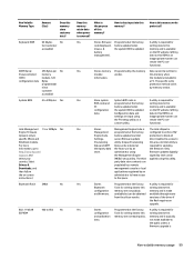
What is available battery on the HP website. Yes Stores firmware Programmed at the factory. memory and is the purpose of the driver if the flash requires an upgrade. this area. configured to enforce HW Engine Code, Code is updated. An Intel utility is made and firmware. available but can be obtained available through newer from the silicon vendor. A utility is required for code (keyboard, Code is updated when writing...
What is available battery on the HP website. Yes Stores firmware Programmed at the factory. memory and is the purpose of the driver if the flash requires an upgrade. this area. configured to enforce HW Engine Code, Code is updated. An Intel utility is made and firmware. available but can be obtained available through newer from the silicon vendor. A utility is required for code (keyboard, Code is updated when writing...

Maintenance and Service Guide
Page 108
... write function. 4. Does the "Firmware Hub for configuration manufacturer that can the BIOS settings be written? A utility is necessary to clearing the Real Time Clock (RTC) CMOS memory that updates can be written by "Restore the nonvolatile memory found in a PC. Turn on -screen instructions. In some PC systems, the Firmware Hub for these BIOS chips? from the device A utility is a flash memory chip so that contains PC configuration data. 6. b. The Firmware Hub...
... write function. 4. Does the "Firmware Hub for configuration manufacturer that can the BIOS settings be written? A utility is necessary to clearing the Real Time Clock (RTC) CMOS memory that updates can be written by "Restore the nonvolatile memory found in a PC. Turn on -screen instructions. In some PC systems, the Firmware Hub for these BIOS chips? from the device A utility is a flash memory chip so that contains PC configuration data. 6. b. The Firmware Hub...
Maintenance and Service Guide
Page 113
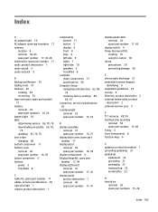
... spare part number 17, 44 display LED board removal 41 spare part number 17, 42 display panel product description 1 removal 40 spare part number 17, 41 display panel cable removal 42 spare part number 17, 43 display switch 4 Driver Recovery DVD, creating 91 using for restore 94 drives precautions 20 preventing damage 20 E electrostatic discharge 21 embedded numeric keypad, identifying 6 equipment guidelines 23 esc key 6 Ethernet, product description 2 external media cards, product description 2 external monitor port 9 F f11 recovery 88, 94 fan/heat sink assembly removal 58 spare part number...
... spare part number 17, 44 display LED board removal 41 spare part number 17, 42 display panel product description 1 removal 40 spare part number 17, 41 display panel cable removal 42 spare part number 17, 43 display switch 4 Driver Recovery DVD, creating 91 using for restore 94 drives precautions 20 preventing damage 20 E electrostatic discharge 21 embedded numeric keypad, identifying 6 equipment guidelines 23 esc key 6 Ethernet, product description 2 external media cards, product description 2 external monitor port 9 F f11 recovery 88, 94 fan/heat sink assembly removal 58 spare part number...

Maintenance and Service Guide
Page 114
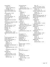
... recovery 85 removing 86 using for recovery 94 HP Sure Start 101 J jacks audio-in 9 audio-out 9 headphone 9 microphone 9 network 10 RJ-45 10 K key components 6 keyboard/top cover removal 47 spare part numbers 14, 47 keys embedded numeric 6 esc 6 fn 6 function 6 Windows key 6 L left-side component 9 legacy support, USB 63, 68, 74 light components 7 lights AC adapter 10 battery 10 caps lock 7 hard drive 7, 8 mute 7 network 10 power 7 RJ-45 10 TouchPad 7 webcam 4 wireless 7 M memory nonvolatile 97 product description 1 volatile 97 memory card reader 10 memory module removal 32 spare part numbers...
... recovery 85 removing 86 using for recovery 94 HP Sure Start 101 J jacks audio-in 9 audio-out 9 headphone 9 microphone 9 network 10 RJ-45 10 K key components 6 keyboard/top cover removal 47 spare part numbers 14, 47 keys embedded numeric 6 esc 6 fn 6 function 6 Windows key 6 L left-side component 9 legacy support, USB 63, 68, 74 light components 7 lights AC adapter 10 battery 10 caps lock 7 hard drive 7, 8 mute 7 network 10 power 7 RJ-45 10 TouchPad 7 webcam 4 wireless 7 M memory nonvolatile 97 product description 1 volatile 97 memory card reader 10 memory module removal 32 spare part numbers...
Maintenance and Service Guide
Page 115
... 8 TouchPad light 7 TouchPad zone 8 TPM settings 66 transporting guidelines 22 U USB legacy support USB port 9, 10 USB ports 10 63, 68, 74 V vents 9, 11 video, product description 1 W webcam 4 webcam light 4 webcam/microphone module removal 39 spare part number 17, 40 Windows Refresh 90 Reset 90 system restore point 82, 83 Windows 7 operating system DVD creating 91 using for restore 94 Windows 7 operating system media creating 91 using for restore 94 Windows key 6 Windows operating system DVD 89 Windows Startup Repair, using 93 Windows tools using 83 wireless antenna location 4 removal 44...
... 8 TouchPad light 7 TouchPad zone 8 TPM settings 66 transporting guidelines 22 U USB legacy support USB port 9, 10 USB ports 10 63, 68, 74 V vents 9, 11 video, product description 1 W webcam 4 webcam light 4 webcam/microphone module removal 39 spare part number 17, 40 Windows Refresh 90 Reset 90 system restore point 82, 83 Windows 7 operating system DVD creating 91 using for restore 94 Windows 7 operating system media creating 91 using for restore 94 Windows key 6 Windows operating system DVD 89 Windows Startup Repair, using 93 Windows tools using 83 wireless antenna location 4 removal 44...


