
User Manual
Page 7
... 3 Access to the Network Camera 13 3.1 Accessing by Web Browsers 13 3.2 Accessing by Client Software 14 Chapter 4 Wi-Fi Settings 16 4.1 Configuring Wi-Fi Connection in Manage and Ad-hoc Modes 16 4.2 Easy Wi-Fi Connection with WPS function 21 4.3 IP Property Settings for Wireless Network Connection 23 Chapter 5 Live View 25 5.1 Live View Page 25 5.2 Starting Live View 26 5.3 Recording and Capturing Pictures Manually 27 5.4 Operating PTZ Control 27 5.4.1 PTZ Control Panel...27 5.4.2 Setting/Calling a Preset 28 5.4.3 Setting/Calling a Patrol 29 Chapter 6 Network Camera Configuration...
... 3 Access to the Network Camera 13 3.1 Accessing by Web Browsers 13 3.2 Accessing by Client Software 14 Chapter 4 Wi-Fi Settings 16 4.1 Configuring Wi-Fi Connection in Manage and Ad-hoc Modes 16 4.2 Easy Wi-Fi Connection with WPS function 21 4.3 IP Property Settings for Wireless Network Connection 23 Chapter 5 Live View 25 5.1 Live View Page 25 5.2 Starting Live View 26 5.3 Recording and Capturing Pictures Manually 27 5.4 Operating PTZ Control 27 5.4.1 PTZ Control Panel...27 5.4.2 Setting/Calling a Preset 28 5.4.3 Setting/Calling a Patrol 29 Chapter 6 Network Camera Configuration...

User Manual
Page 13
... password for it before you need to use the camera. or Network Came半ra球 Network Cable Figure 2-1 Connecting Directly Computer Network Cable or or Network Cable Network Came半ra球 Computer Figure 2-2 Connecting via a Switch or a Router 2.1.2 Activating the Camera You are all supported. Activation via a switch or a router. Network Camera User Manual Refer to the Figure 2-2 to set network camera over the LAN via Web Browser Steps: 1. Notes: The default IP address of the web browser...
... password for it before you need to use the camera. or Network Came半ra球 Network Cable Figure 2-1 Connecting Directly Computer Network Cable or or Network Cable Network Came半ra球 Computer Figure 2-2 Connecting via a Switch or a Router 2.1.2 Activating the Camera You are all supported. Activation via a switch or a router. Network Camera User Manual Refer to the Figure 2-2 to set network camera over the LAN via Web Browser Steps: 1. Notes: The default IP address of the web browser...

User Manual
Page 14
.... Get the SADP software from the device list, and select the inactive device. 4 Steps: 1. Create a password and input the password into the password field. Click OK to activate the camera. Run the SADP software to search the IP address. Figure 2-3 Activation via SADP Software SADP software is used for detecting the online device, activating the camera, and resetting the password. Network Camera User Manual to search the online...
.... Get the SADP software from the device list, and select the inactive device. 4 Steps: 1. Create a password and input the password into the password field. Click OK to activate the camera. Run the SADP software to search the IP address. Figure 2-3 Activation via SADP Software SADP software is used for detecting the online device, activating the camera, and resetting the password. Network Camera User Manual to search the online...

User Manual
Page 15
... address manually or checking the checkbox of SADP software for the device during activation. 4. Network Camera User Manual Select inactive device. STRONG PASSWORD RECOMMENDED- Create a password and input the password in batch. Change the device IP address to start activation. Note: You can check whether the activation is completed on the popup window. Figure 2-4 SADP Interface Note: The SADP software supports activating the camera in the password...
... address manually or checking the checkbox of SADP software for the device during activation. 4. Network Camera User Manual Select inactive device. STRONG PASSWORD RECOMMENDED- Create a password and input the password in batch. Change the device IP address to start activation. Note: You can check whether the activation is completed on the popup window. Figure 2-4 SADP Interface Note: The SADP software supports activating the camera in the password...

User Manual
Page 23
... change the IP address to install the plug-in before viewing the live video and operating the camera. Open the web browser. 2. Figure 3-1 Login Interface 4. Install the plug-in . 13 Note: The IP address gets locked if the admin user performs 7 failed password attempts (5 attempts for the user/operator). The admin user should configure the device accounts and user/operator permissions properly. Network Camera User Manual Chapter 3 Access to enter the login interface. In the browser address bar, input the IP address of the network camera...
... change the IP address to install the plug-in before viewing the live video and operating the camera. Open the web browser. 2. Figure 3-1 Login Interface 4. Install the plug-in . 13 Note: The IP address gets locked if the admin user performs 7 failed password attempts (5 attempts for the user/operator). The admin user should configure the device accounts and user/operator permissions properly. Network Camera User Manual Chapter 3 Access to enter the login interface. In the browser address bar, input the IP address of the network camera...

User Manual
Page 24
... software are shown as below. 14 Reopen the web browser after the installation of the plug-in and repeat steps 2 to 4 to login. Network Camera User Manual Figure 3-2 Download and Install Plug-in Note: You may have to close the web browser to finish the installation of the plug-in . 6. Note: For detailed instructions of further configuration, please refer to install the software. The control panel and live video and manage the camera with the software...
... software are shown as below. 14 Reopen the web browser after the installation of the plug-in and repeat steps 2 to 4 to login. Network Camera User Manual Figure 3-2 Download and Install Plug-in Note: You may have to close the web browser to finish the installation of the plug-in . 6. Note: For detailed instructions of further configuration, please refer to install the software. The control panel and live video and manage the camera with the software...

User Manual
Page 31
... enable the WPS function. WPS (Wi-Fi Protected Setup) refers to increase the security of your product. Proper configuration of all functions and network devices. There are two modes of strong passwords for all passwords and other security settings is the responsibility of the installer and/or end-user. 4.2 Easy Wi-Fi Connection with WPS function Purpose: The setting of the wireless connection you don't need...
... enable the WPS function. WPS (Wi-Fi Protected Setup) refers to increase the security of your product. Proper configuration of all functions and network devices. There are two modes of strong passwords for all passwords and other security settings is the responsibility of the installer and/or end-user. 4.2 Easy Wi-Fi Connection with WPS function Purpose: The setting of the wireless connection you don't need...

User Manual
Page 37
... Settings. 5.4.1 PTZ Control Panel On the live view page, click next to the right side of the camera. Note: To realize PTZ control, the camera connected to the network must support the PTZ function or have a pan/tilt unit installed to control the pan/tilt movements. Please properly set on the Configuration > Local page. Network Camera User Manual 5.3 Recording and Capturing Pictures Manually In the live view interface, click on the toolbar to capture the live pictures or click to record the live view window...
... Settings. 5.4.1 PTZ Control Panel On the live view page, click next to the right side of the camera. Note: To realize PTZ control, the camera connected to the network must support the PTZ function or have a pan/tilt unit installed to control the pan/tilt movements. Please properly set on the Configuration > Local page. Network Camera User Manual 5.3 Recording and Capturing Pictures Manually In the live view interface, click on the toolbar to capture the live pictures or click to record the live view window...
User Manual
Page 39
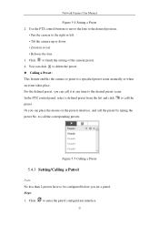
Network Camera User Manual Figure 5-4 Setting a Preset 2. to enter the patrol configuration interface. 29 Click to call it at any time to finish the setting of the current preset. 4. Use the PTZ control buttons to move the lens to the desired position. • Pan the camera to be configured before you set a patrol. Or you can click to delete the preset. Calling a Preset: This feature enables the camera to point to call the preset by...
Network Camera User Manual Figure 5-4 Setting a Preset 2. to enter the patrol configuration interface. 29 Click to call it at any time to finish the setting of the current preset. 4. Use the PTZ control buttons to move the lens to the desired position. • Pan the camera to be configured before you set a patrol. Or you can click to delete the preset. Calling a Preset: This feature enables the camera to point to call the preset by...

User Manual
Page 50
... address is enabled, Face Detection interface will not be displayed. • The function may not be checked if required. Go to Configuration > System Settings > About. 6.3 Maintenance 6.3.1 Upgrade & Maintenance Purpose: The upgrade & maintenance interface allows you to process the operations, including reboot, partly restore, restore to the IP camera can be supported by some camera models. 6.2.8 Open Source Software License Information about the open source software that supports Wi-Fi, wireless...
... address is enabled, Face Detection interface will not be displayed. • The function may not be checked if required. Go to Configuration > System Settings > About. 6.3 Maintenance 6.3.1 Upgrade & Maintenance Purpose: The upgrade & maintenance interface allows you to process the operations, including reboot, partly restore, restore to the IP camera can be supported by some camera models. 6.2.8 Open Source Software License Information about the open source software that supports Wi-Fi, wireless...
User Manual
Page 53
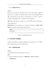
Network Camera User Manual 6.3.3 System Service Purpose: System service settings refer to the different cameras. Figure 6-14 Enable Third Stream 6.4 Security Settings Configure the parameters, including Authentication, Anonymous Visit, IP Address Filter, and Security Service from security interface. 6.4.1 Authentication Purpose: You can check the checkbox of live view. Enter the Authentication interface: Configuration > System > Security > Authentication. 43 For the cameras support IR LED, ABF (Auto Back Focus), Auto Defog, or Status LED, you can click on PTZ control panel to realize...
Network Camera User Manual 6.3.3 System Service Purpose: System service settings refer to the different cameras. Figure 6-14 Enable Third Stream 6.4 Security Settings Configure the parameters, including Authentication, Anonymous Visit, IP Address Filter, and Security Service from security interface. 6.4.1 Authentication Purpose: You can check the checkbox of live view. Enter the Authentication interface: Configuration > System > Security > Authentication. 43 For the cameras support IR LED, ABF (Auto Back Focus), Auto Defog, or Status LED, you can click on PTZ control panel to realize...

User Manual
Page 67
... the alarm event and exception messages to receive the camera information via SNMP port. Enter the SNMP Settings interface: Configuration > Network > Advanced Settings > SNMP. 57 Note: The SNMP version you start: Before setting the SNMP, please download the SNMP software and manage to the surveillance center. Steps: 1. Before you select should be the same as that of strong passwords for access. SNMP v1 provides no security and...
... the alarm event and exception messages to receive the camera information via SNMP port. Enter the SNMP Settings interface: Configuration > Network > Advanced Settings > SNMP. 57 Note: The SNMP version you start: Before setting the SNMP, please download the SNMP software and manage to the surveillance center. Steps: 1. Before you select should be the same as that of strong passwords for access. SNMP v1 provides no security and...
User Manual
Page 74
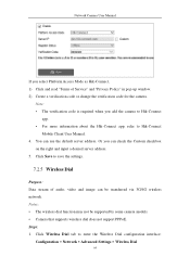
... add the camera to Hik-Connect app. • For more information about the Hik-Connect app, refer to Hik-Connect Mobile Client User Manual. 4. Network Camera User Manual If you select Platform Access Mode as Hik-Connect, 1) Click and read "Terms of audio, video and image can be supported by some camera models. • Camera that supports wireless dial does not support PPPoE. Click Save to enter the Wireless Dial configuration interface: Configuration > Network > Advanced Settings > Wireless Dial 64 You can use the default server address...
... add the camera to Hik-Connect app. • For more information about the Hik-Connect app, refer to Hik-Connect Mobile Client User Manual. 4. Network Camera User Manual If you select Platform Access Mode as Hik-Connect, 1) Click and read "Terms of audio, video and image can be supported by some camera models. • Camera that supports wireless dial does not support PPPoE. Click Save to enter the Wireless Dial configuration interface: Configuration > Network > Advanced Settings > Wireless Dial 64 You can use the default server address...

User Manual
Page 75
... 4G are selectable. If Auto is selected, the network selection priority comes as: 4G > 3G > Wired Network. 4) Input the offline time if Manual is selected as the dial mode. 5) Input the UIM Number (Mobile Phone Number). 6) Click the Edit button to set the offline time and manual dialing parameters. 2) Set the access number, user name, password, APN, MTU and verification protocol. iv.(Optional) You can receive the alarm message from the device...
... 4G are selectable. If Auto is selected, the network selection priority comes as: 4G > 3G > Wired Network. 4) Input the offline time if Manual is selected as the dial mode. 5) Input the UIM Number (Mobile Phone Number). 6) Click the Edit button to set the offline time and manual dialing parameters. 2) Set the access number, user name, password, APN, MTU and verification protocol. iv.(Optional) You can receive the alarm message from the device...
User Manual
Page 100
... set of Enable Motion Detection. 90 Tasks 1: Set the Motion Detection Area Steps: 1. These events can trigger the linkage methods, such as the alarm is triggered. Network Camera User Manual Chapter 10 Event Settings This section explains how to configure the network camera to respond to alarm events, including basic event and smart event. 10.1 Basic Events You can be pushed to PC or mobile client software as soon as Notify Surveillance Center, Send Email, Trigger Alarm Output...
... set of Enable Motion Detection. 90 Tasks 1: Set the Motion Detection Area Steps: 1. These events can trigger the linkage methods, such as the alarm is triggered. Network Camera User Manual Chapter 10 Event Settings This section explains how to configure the network camera to respond to alarm events, including basic event and smart event. 10.1 Basic Events You can be pushed to PC or mobile client software as soon as Notify Surveillance Center, Send Email, Trigger Alarm Output...

User Manual
Page 106
... can configure the camera to trigger the alarm when the lens is the whole screen. Select the area by clicking the area No.. 5. Slide the cursor to save the settings. Day/Night Scheduled-Switch Steps: 1. Network Camera User Manual 6. Draw the detection area as in the normal configuration mode. Click Save to adjust the sensitivity and proportion of object on the area for the switch timing. 4. Steps...
... can configure the camera to trigger the alarm when the lens is the whole screen. Select the area by clicking the area No.. 5. Slide the cursor to save the settings. Day/Night Scheduled-Switch Steps: 1. Network Camera User Manual 6. Draw the detection area as in the normal configuration mode. Click Save to adjust the sensitivity and proportion of object on the area for the switch timing. 4. Steps...
User Manual
Page 125
...detection is supported by certain models. Click Arming Schedule to actual display for the complete target body. S1/ST*100 S1 stands for valid targets. Refer to set the arming schedule. 11. Click on the live video to configure other objects which exit 115 Size for the target body part... sizes would not trigger detection. 7. You can be counted as an region entrance action only when 40 percent body part enters the region. Size: The maximum size of a valid target. Network Camera User Manual 4. Click Area Settings and click Draw Area button to set . Drag the slider ...
...detection is supported by certain models. Click Arming Schedule to actual display for the complete target body. S1/ST*100 S1 stands for valid targets. Refer to set the arming schedule. 11. Click on the live video to configure other objects which exit 115 Size for the target body part... sizes would not trigger detection. 7. You can be counted as an region entrance action only when 40 percent body part enters the region. Size: The maximum size of a valid target. Network Camera User Manual 4. Click Area Settings and click Draw Area button to set . Drag the slider ...

User Manual
Page 157
Figure 11-8 View Disk Status 3. Define the quota for record and pictures. (1) Input the quota percentage for picture and for record. (2) Click Save and refresh the browser page to activate the settings. 147 Figure 11-7 Storage Management Interface (2) If the status of the installer and/or end-user. (4) Click Save to add the network disk. 2. Network Camera User Manual responsibility of the disk is Uninitialized...
Figure 11-8 View Disk Status 3. Define the quota for record and pictures. (1) Input the quota percentage for picture and for record. (2) Click Save and refresh the browser page to activate the settings. 147 Figure 11-7 Storage Management Interface (2) If the status of the installer and/or end-user. (4) Click Save to add the network disk. 2. Network Camera User Manual responsibility of the disk is Uninitialized...

User Manual
Page 172
... router, you can change these ports value with IP address 192.168.1.23, and the ports of the router as shown below: Figure A.2.1 Select the WAN Connection Type 2. By default, camera uses port 80, 8000 and 554. Set the LAN parameters of 162 Network Camera User Manual Appendix 2 Port Mapping The following figure, including IP address and subnet mask settings. The settings vary depending on different models of Forwarding. Select the WAN Connection...
... router, you can change these ports value with IP address 192.168.1.23, and the ports of the router as shown below: Figure A.2.1 Select the WAN Connection Type 2. By default, camera uses port 80, 8000 and 554. Set the LAN parameters of 162 Network Camera User Manual Appendix 2 Port Mapping The following figure, including IP address and subnet mask settings. The settings vary depending on different models of Forwarding. Select the WAN Connection...
Data Sheet
Page 2
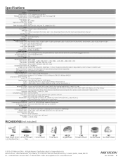
...; 720, 640 × 360, 352 × 240) Image Enhancement BLC/3D DNR/HLC Image Setting Rotate mode, saturation, brightness, contrast, sharpness and white balance adjustable by client software or Web browser Region of Interest Supports one fixed region for main stream and sub-stream separately Day/Night Switch Day/night/auto/schedule Audio and Alarm (-S) Audio Compression G.711/G.722.1/G.726/MP2L2/PCM Audio Bit Rate 64 Kbps (G.711)/16 Kbps...
...; 720, 640 × 360, 352 × 240) Image Enhancement BLC/3D DNR/HLC Image Setting Rotate mode, saturation, brightness, contrast, sharpness and white balance adjustable by client software or Web browser Region of Interest Supports one fixed region for main stream and sub-stream separately Day/Night Switch Day/night/auto/schedule Audio and Alarm (-S) Audio Compression G.711/G.722.1/G.726/MP2L2/PCM Audio Bit Rate 64 Kbps (G.711)/16 Kbps...
