User Guide
Page 3
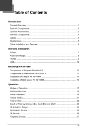
... 4 Labels...5 Maintenance...5 Cable Installation and Removal 6 Interface Installation RS232 ...7 Keyboard Wedge 8 RS485 ...9 USB ...10 Mounting the MS7580 Components of Adapter Kit 46-00911 13 Components of Wall Mount Kit 46-00913 13 Installation of Adapter Kit 46-00911 14 Installation of Wall Mount Kit 46-00913 16 Operation Modes of Operation 17 Audible Indicators 19 Visual Indicators 20 Failure Modes...
... 4 Labels...5 Maintenance...5 Cable Installation and Removal 6 Interface Installation RS232 ...7 Keyboard Wedge 8 RS485 ...9 USB ...10 Mounting the MS7580 Components of Adapter Kit 46-00911 13 Components of Wall Mount Kit 46-00913 13 Installation of Adapter Kit 46-00911 14 Installation of Wall Mount Kit 46-00913 16 Operation Modes of Operation 17 Audible Indicators 19 Visual Indicators 20 Failure Modes...
User Guide
Page 7
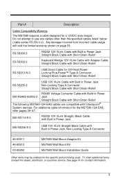
...Jack Straight Black Cable with Short Strain Relief The following MS7580-124-EAS cables are compatible with Build in Power Jack, Non-Locking Type A Connector 46-00911 46-00913 00-05250 MS7580 Wall Mount Adapter Kit MS7580 Wall Mount Kit MS7580 Wall Mount Installation Guide Other items may be ordered for a ...12VDC area imager. See page 61 for the MS7580-124-EAS, refer pages 39-47. Do not attempt to...
...Jack Straight Black Cable with Short Strain Relief The following MS7580-124-EAS cables are compatible with Build in Power Jack, Non-Locking Type A Connector 46-00911 46-00913 00-05250 MS7580 Wall Mount Adapter Kit MS7580 Wall Mount Kit MS7580 Wall Mount Installation Guide Other items may be ordered for a ...12VDC area imager. See page 61 for the MS7580-124-EAS, refer pages 39-47. Do not attempt to...
User Guide
Page 17
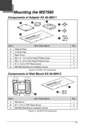
Mounting the MS7580 Components of Wall Mount Kit 46-00913 Item Item Description A Wall Mount B #7 x 1.00 in . FHP Wood Screw C MS7580 Wall Mount Installation Guide Figure 10. 46-00913 Kit Components Qty. 1 2 1 13 FHP Wood Screw G MS7580 Wall Mount Installation Guide Figure 9. 46-00911 Kit Components Qty. 1 1 1 4 4 3 1 Components of Adapter Kit 46-00911 Item Item Description A Adapter Plate B Locking Plate C Base Cover D M3 x .5 - 10 mm Flat Head Phillips Screw E M3 x .5 - 8 mm Flat Head Phillips Screw F #7 x 1.00 in .
Mounting the MS7580 Components of Wall Mount Kit 46-00913 Item Item Description A Wall Mount B #7 x 1.00 in . FHP Wood Screw C MS7580 Wall Mount Installation Guide Figure 10. 46-00913 Kit Components Qty. 1 2 1 13 FHP Wood Screw G MS7580 Wall Mount Installation Guide Figure 9. 46-00911 Kit Components Qty. 1 1 1 4 4 3 1 Components of Adapter Kit 46-00911 Item Item Description A Adapter Plate B Locking Plate C Base Cover D M3 x .5 - 10 mm Flat Head Phillips Screw E M3 x .5 - 8 mm Flat Head Phillips Screw F #7 x 1.00 in .

User Guide
Page 19
Figure 13. Secure the locking plate to lock the imager into place. Twist the imager 90° counter-clockwise to the wall with the three #7 wood screws () provided in the mounting surface. Figure 15 15 Use the locking plate as a guide to Scale) 6. Figure 14 7. 5. Position the imager so the base plate sits flush over the locking plate. Locking Plate (Not Drawn to drill three #39 pilot holes (A) in the kit.
Figure 13. Secure the locking plate to lock the imager into place. Twist the imager 90° counter-clockwise to the wall with the three #7 wood screws () provided in the mounting surface. Figure 15 15 Use the locking plate as a guide to Scale) 6. Figure 14 7. 5. Position the imager so the base plate sits flush over the locking plate. Locking Plate (Not Drawn to drill three #39 pilot holes (A) in the kit.

User Guide
Page 20
The pilot holes should be centered vertically 44 mm apart. 2. Secure the wall mount to the wall with the arrow pointing up. 3. Figure 17 16 Position the wall mount over the pilot holes with the two #7 wood screws () provided in and down behind the lower corner tabs. Slide the imager's base under the upper corner tabs on the wall mount. 5. Slide the remainder of Wall Mount Kit 46-00913 1. Figure 16 4. Installation of the base in the kit. Drill two #39 pilot holes in the mounting surface.
The pilot holes should be centered vertically 44 mm apart. 2. Secure the wall mount to the wall with the arrow pointing up. 3. Figure 17 16 Position the wall mount over the pilot holes with the two #7 wood screws () provided in and down behind the lower corner tabs. Slide the imager's base under the upper corner tabs on the wall mount. 5. Slide the remainder of Wall Mount Kit 46-00913 1. Figure 16 4. Installation of the base in the kit. Drill two #39 pilot holes in the mounting surface.