Owner's Manual
Page 3
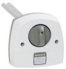
... lamp handle; Consult Honeywell's UV exposure white paper, Form No. 50-8788. Can cause personal injury. Talk to your local heating and cooling contractor about adding an electronic air cleaner to ultraviolet light. BE SURE TO READ WARNINGS AND CAUTIONS BEFORE INSTALLING OR USING YOUR UV SYSTEM... WARNING UV Light Hazard. Harmful to bypass duct mount switch. CAUTION Personal Injury Hazard. Do not open housing; Be careful when inserting ...
... lamp handle; Consult Honeywell's UV exposure white paper, Form No. 50-8788. Can cause personal injury. Talk to your local heating and cooling contractor about adding an electronic air cleaner to ultraviolet light. BE SURE TO READ WARNINGS AND CAUTIONS BEFORE INSTALLING OR USING YOUR UV SYSTEM... WARNING UV Light Hazard. Harmful to bypass duct mount switch. CAUTION Personal Injury Hazard. Do not open housing; Be careful when inserting ...

Owner's Manual
Page 4
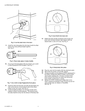
..., such as isolators, in . (mm). Ultraviolet System dimensions in in the duct. See Fig 5. The UV Surface Treatment System requires an easily-accessible, flat mounting surface on the metal supply air duct of the unit to plug in these instructions carefully. The UV Surface Treatment System must be located so the lamp surrounds the evaporator coil and drip...
..., such as isolators, in . (mm). Ultraviolet System dimensions in in the duct. See Fig 5. The UV Surface Treatment System requires an easily-accessible, flat mounting surface on the metal supply air duct of the unit to plug in these instructions carefully. The UV Surface Treatment System must be located so the lamp surrounds the evaporator coil and drip...

Owner's Manual
Page 5
... the screws so the space between the case and duct is flat after all holes are drilled. 6. CENTER OF 2 IN. (51 MM) HOLE FOR LAMP ULTRAVIOLET SYSTEM ALIGN EITHER OF THESE LINES AS CLOSE AS POSSIBLE TO DUCT CENTER LINE 3/32 IN. (3 MM) PILOT HOLES FOR MOUNTING SCREWS M18991 Fig.... 4. Ultraviolet System template. 4. Phillips head sheet metal mounting screws provided. 8. drill to allow bulb insertion. 7. Install the unit on the duct. Use a 3/32 in. Position...
... the screws so the space between the case and duct is flat after all holes are drilled. 6. CENTER OF 2 IN. (51 MM) HOLE FOR LAMP ULTRAVIOLET SYSTEM ALIGN EITHER OF THESE LINES AS CLOSE AS POSSIBLE TO DUCT CENTER LINE 3/32 IN. (3 MM) PILOT HOLES FOR MOUNTING SCREWS M18991 Fig.... 4. Ultraviolet System template. 4. Phillips head sheet metal mounting screws provided. 8. drill to allow bulb insertion. 7. Install the unit on the duct. Use a 3/32 in. Position...
Owner's Manual
Page 6
.... See Fig. 6. Insert bulb into place. 14. Use cloth to drop into the lamp handle by aligning the key and pushing straight together. Continue lightly pushing in the air treatment system packing box. Choose a location on the adjacent HVAC equipment for the HVAC maintenance label included... lamp indicator light aligned with the lamp light indi- Choose a location that a future service technician can easily see during any future HVAC maintenance or repair. 17. Adhere the HVAC maintenance safety label to the HVAC system. 16. See Fig. 10. 69-1859EFS-01 6 ULTRAVIOLET SYSTEM ...
.... See Fig. 6. Insert bulb into place. 14. Use cloth to drop into the lamp handle by aligning the key and pushing straight together. Continue lightly pushing in the air treatment system packing box. Choose a location on the adjacent HVAC equipment for the HVAC maintenance label included... lamp indicator light aligned with the lamp light indi- Choose a location that a future service technician can easily see during any future HVAC maintenance or repair. 17. Adhere the HVAC maintenance safety label to the HVAC system. 16. See Fig. 10. 69-1859EFS-01 6 ULTRAVIOLET SYSTEM ...
Owner's Manual
Page 7
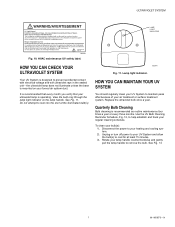
... safety label. HOW YOU CAN MAINTAIN YOUR UV SYSTEM You should regularly clean your UV System to remove the bulb. To clean your air treatment or surface treatment system. Do not attempt to prevent accidental contact with electrical voltage and with ultraviolet rays in the sealed unit⎯the ultraviolet lamp does not illuminate unless the base is recommended...
... safety label. HOW YOU CAN MAINTAIN YOUR UV SYSTEM You should regularly clean your UV System to remove the bulb. To clean your air treatment or surface treatment system. Do not attempt to prevent accidental contact with electrical voltage and with ultraviolet rays in the sealed unit⎯the ultraviolet lamp does not illuminate unless the base is recommended...

Owner's Manual
Page 8
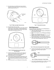
Remove lamp bulb. 4. UV bulb cleaning reminder schedule. M22842 69-1859EFS-01 Fig. 14. M22844 8 Holding the lamp handle, wipe the lamp glass using a soft cloth dampened with your hands, be sure to clean the area of any oils left from bare hands. See Fig. 14. If you touch the lamp glass with glass cleaner. ULTRAVIOLET SYSTEM UV BULB CLEANING REMINDER SCHEDULE INSTALLATION DATE: (month) , (year) YEAR J F M A M J J A S O N D Fig. 12. M13516A Fig. 13. Clean glass with soft cloth.
Remove lamp bulb. 4. UV bulb cleaning reminder schedule. M22842 69-1859EFS-01 Fig. 14. M22844 8 Holding the lamp handle, wipe the lamp glass using a soft cloth dampened with your hands, be sure to clean the area of any oils left from bare hands. See Fig. 14. If you touch the lamp glass with glass cleaner. ULTRAVIOLET SYSTEM UV BULB CLEANING REMINDER SCHEDULE INSTALLATION DATE: (month) , (year) YEAR J F M A M J J A S O N D Fig. 12. M13516A Fig. 13. Clean glass with soft cloth.
Owner's Manual
Page 9
... required to your ultraviolet bulbs are operating by align- Reconnect power to your heating and cooling system. 3. See Fig. 7 9 69-1859EFS-01 See Fig. 15. See Fig. 16. RUVBULB1) for your retailer. 2. Grasp the lamp handle in one hand and the lamp glass in lamp handle. 7. Rotate the lamp handle clockwise until the lamp handle inserts fully...
... required to your ultraviolet bulbs are operating by align- Reconnect power to your heating and cooling system. 3. See Fig. 7 9 69-1859EFS-01 See Fig. 15. See Fig. 16. RUVBULB1) for your retailer. 2. Grasp the lamp handle in one hand and the lamp glass in lamp handle. 7. Rotate the lamp handle clockwise until the lamp handle inserts fully...

Owner's Manual
Page 10
...base. See Fig 16. 9. See Fig. 17. 10. Verify that your UV System. 11. Continue pushing and gently rotating counterclockwise until it is operating by viewing only through the lamp light indicator on the unit cover. Reconnect power to your bulb while it snaps ... with the raised button on the lamp handle. Insert the bulb into place with the lamp light indicator aligned with the lamp light indicator at your heating and cooling system. 69-1859EFS-01 10 Reconnect power to your ultraviolet bulb is illuminated. 12. ULTRAVIOLET SYSTEM 8. Never look directly at the ...
...base. See Fig 16. 9. See Fig. 17. 10. Verify that your UV System. 11. Continue pushing and gently rotating counterclockwise until it is operating by viewing only through the lamp light indicator on the unit cover. Reconnect power to your bulb while it snaps ... with the raised button on the lamp handle. Insert the bulb into place with the lamp light indicator aligned with the lamp light indicator at your heating and cooling system. 69-1859EFS-01 10 Reconnect power to your ultraviolet bulb is illuminated. 12. ULTRAVIOLET SYSTEM 8. Never look directly at the ...