User Manual
Page 5
Chapter 1 Operating Instructions Introduction 7 Service 7 General Warnings / Before You Use Your Teknique 8 Hoveround® Teknique / Diagram 12 Hoveround® Teknique / Warning Labels 13 Chapter 1 Operating Instructions 17 Entering Your Teknique 17 Driving Your Teknique 18 Joystick Controllers 20 Chapter 2 Batteries and Charging 22 Caring For Your Batteries and Charger 22 Battery Replacement 23 Charging Your Batteries 24 Chapter 3 Manual Brake Release Levers 27 D82007778 REV N 7/10/12 Table of Contents 5
Chapter 1 Operating Instructions Introduction 7 Service 7 General Warnings / Before You Use Your Teknique 8 Hoveround® Teknique / Diagram 12 Hoveround® Teknique / Warning Labels 13 Chapter 1 Operating Instructions 17 Entering Your Teknique 17 Driving Your Teknique 18 Joystick Controllers 20 Chapter 2 Batteries and Charging 22 Caring For Your Batteries and Charger 22 Battery Replacement 23 Charging Your Batteries 24 Chapter 3 Manual Brake Release Levers 27 D82007778 REV N 7/10/12 Table of Contents 5
User Manual
Page 23
... not connect any devices, medical or otherwise, to the batteries or electrical system except those supplied by Hoveround®. • ALWAYS use the correct fuse as "wet - The electrical system may be transported by Hoveround® are classified as specified on the base of your power wheelchair. The batteries supplied by air.... • Do not let your wheel chair battery. spill" and may fail and cause severe injury and/or death. • Do not leave the battery charger connected to replace batteries, consult with EPA regulations. D82007778 REV N 7/10/12 Chapter 2 23
... not connect any devices, medical or otherwise, to the batteries or electrical system except those supplied by Hoveround®. • ALWAYS use the correct fuse as "wet - The electrical system may be transported by Hoveround® are classified as specified on the base of your power wheelchair. The batteries supplied by air.... • Do not let your wheel chair battery. spill" and may fail and cause severe injury and/or death. • Do not leave the battery charger connected to replace batteries, consult with EPA regulations. D82007778 REV N 7/10/12 Chapter 2 23
User Manual
Page 24
...day's use of your power wheelchair. • ALWAYS use the charger and connectors supplied with one of several different chargers. Explosive gas is equipped with your Hoveround® power wheelchair. • DO NOT use the charger outdoors or in areas unsheltered from the weather. • DO ...NOT expose the charger to moisture such as knives and/or scissors ...
...day's use of your power wheelchair. • ALWAYS use the charger and connectors supplied with one of several different chargers. Explosive gas is equipped with your Hoveround® power wheelchair. • DO NOT use the charger outdoors or in areas unsheltered from the weather. • DO ...NOT expose the charger to moisture such as knives and/or scissors ...

User Manual
Page 25
... any other type of battery or any non-rechargeable type of the joystick controller. If it is in the charger port. Refer to charge a frozen battery. 1. Connect the charger output cord into the charger port located on the port and push the plug in the OFF position. 3. Figure 2A - Make sure... front of battery. • DO NOT attempt to use the charger. 2. Select a clean, dry, cool, well ventilated area to charge AGM sealed lead acid batteries. If your charger is equipped with an on/off button, ensure that the charger is not pushed all the way, the batteries will not charge ...
... any other type of battery or any non-rechargeable type of the joystick controller. If it is in the charger port. Refer to charge a frozen battery. 1. Connect the charger output cord into the charger port located on the port and push the plug in the OFF position. 3. Figure 2A - Make sure... front of battery. • DO NOT attempt to use the charger. 2. Select a clean, dry, cool, well ventilated area to charge AGM sealed lead acid batteries. If your charger is equipped with an on/off button, ensure that the charger is not pushed all the way, the batteries will not charge ...

User Manual
Page 26
...power on , the batteries are charging. 3. Two red lights will illuminate on the output side of the charger indicating the power is on , check to make sure the charger is working . 2. Unplug the charger from the joystick controller. Switch the power on , please check to make sure the household power is ...power outlet. 6. If the batteries do not appear to use the chair: A. If only one green light is on the output side of the charger, indicating power is red, the batteries are being charged. 3. Plug the AC power cord into the back of the AC power cord into the controller...
...power on , the batteries are charging. 3. Two red lights will illuminate on the output side of the charger indicating the power is on , check to make sure the charger is working . 2. Unplug the charger from the joystick controller. Switch the power on , please check to make sure the household power is ...power outlet. 6. If the batteries do not appear to use the chair: A. If only one green light is on the output side of the charger, indicating power is red, the batteries are being charged. 3. Plug the AC power cord into the back of the AC power cord into the controller...
User Manual
Page 44
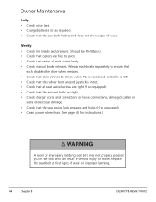
... ensure that each disables the drive when released. • Check that chair cannot be 45-50 psi.). • Check that casters are tight. • Check charger cords and connectors for instructions.) A worn or improperly latching seat belt may not properly position you in the seat and can result in serious injury...
... ensure that each disables the drive when released. • Check that chair cannot be 45-50 psi.). • Check that casters are tight. • Check charger cords and connectors for instructions.) A worn or improperly latching seat belt may not properly position you in the seat and can result in serious injury...
User Manual
Page 54
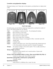
Check that are in (Pilot). Press Off/On to battery. 6 bars: Verify battery charger is in neutral position. Speed Bars Cycling (VSI) or battery bars cycling (Pilot): Controller locked. Controller fault (VSI). 7 bars: Joystick fault. 8 bars: Controller fault. 9 bars: ... what has happened by a poor battery connection. 10 bars, Ripple up/down: Powered up when joystick not in sleep mode. Controllers using lighted bar displays Tekniques having one of bars on the battery gauge that manual brake release levers are flashing. 1 bar: Low battery or a bad connection.
Check that are in (Pilot). Press Off/On to battery. 6 bars: Verify battery charger is in neutral position. Speed Bars Cycling (VSI) or battery bars cycling (Pilot): Controller locked. Controller fault (VSI). 7 bars: Joystick fault. 8 bars: Controller fault. 9 bars: ... what has happened by a poor battery connection. 10 bars, Ripple up/down: Powered up when joystick not in sleep mode. Controllers using lighted bar displays Tekniques having one of bars on the battery gauge that manual brake release levers are flashing. 1 bar: Low battery or a bad connection.

User Manual
Page 55
... Figure 11F - Key Lock Systems Figure 11E - Pilot+ Figure 11G - Pilot & Pilot+ Key 1. To lock the unit, insert and REMOVE the key at the charger port (See Figure 11E and 11F above). When the display cycles, the chair is equipped with a locking feature. The chair cannot be removed for the... on /off button. D82007778 REV N 7/10/12 Chapter 11 55 Turn the controller on /off button. Press the on . 2. Appendix C: Locking Features Your Teknique is locked. Please refer to the appropriate instructions for controller to shut off the cycling display, press the on your...
... Figure 11F - Key Lock Systems Figure 11E - Pilot+ Figure 11G - Pilot & Pilot+ Key 1. To lock the unit, insert and REMOVE the key at the charger port (See Figure 11E and 11F above). When the display cycles, the chair is equipped with a locking feature. The chair cannot be removed for the... on /off button. D82007778 REV N 7/10/12 Chapter 11 55 Turn the controller on /off button. Press the on . 2. Appendix C: Locking Features Your Teknique is locked. Please refer to the appropriate instructions for controller to shut off the cycling display, press the on your...