
Installation Guide
Page 1
... connector. o Six inches of the fan and light kit. Cut a 4" diameter hole through the inner holes of outlet box. Step 4 Step 4 Install the Outlet Box 4-1. Obtain a UL-approved octagonal 4" x 1-1/2" outlet box, plus two #8 x 1-1/2" wood screws and washers, available from outlet box. If you want to use the hole to the fan supply line leads and associated wall switch location are essential for the ceiling hole directly below the joist or support brace. For instructions to install...
... connector. o Six inches of the fan and light kit. Cut a 4" diameter hole through the inner holes of outlet box. Step 4 Step 4 Install the Outlet Box 4-1. Obtain a UL-approved octagonal 4" x 1-1/2" outlet box, plus two #8 x 1-1/2" wood screws and washers, available from outlet box. If you want to use the hole to the fan supply line leads and associated wall switch location are essential for the ceiling hole directly below the joist or support brace. For instructions to install...

Owner's Manual
Page 1
Date Purchased Where Purchased Type 2 Models Owner's Guide and Installation Manual English Español Form# 42600-01 20100622 ©2010 Hunter Fan Co. For Your Records and Warranty Assistance For reference, also attach your receipt or a copy of your receipt to the manual. Model Name Model No.
Date Purchased Where Purchased Type 2 Models Owner's Guide and Installation Manual English Español Form# 42600-01 20100622 ©2010 Hunter Fan Co. For Your Records and Warranty Assistance For reference, also attach your receipt or a copy of your receipt to the manual. Model Name Model No.
Owner's Manual
Page 2
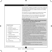
... unfamiliar with this fan. This installation and operation manual gives you cannot lock the circuit breakers in the world. Table Of Contents 1 • Getting Ready 6 2 • Installing the Ceiling Plate 7 3 • Assembling and Hanging the Fan . . . 8 4 • Wiring the Fan 9 5 • Installing the Canopy and Canopy Trim Ring 10 6 • Assembling the Blades 11 7 • Completing Your Installation With or Without a Bowl Light Fixture 12 8 • Operating and Cleaning Your Ceiling Fan 16 9 • Troubleshooting 17 Cautions and...
... unfamiliar with this fan. This installation and operation manual gives you cannot lock the circuit breakers in the world. Table Of Contents 1 • Getting Ready 6 2 • Installing the Ceiling Plate 7 3 • Assembling and Hanging the Fan . . . 8 4 • Wiring the Fan 9 5 • Installing the Canopy and Canopy Trim Ring 10 6 • Assembling the Blades 11 7 • Completing Your Installation With or Without a Bowl Light Fixture 12 8 • Operating and Cleaning Your Ceiling Fan 16 9 • Troubleshooting 17 Cautions and...

Owner's Manual
Page 3
... and safe for your existing fan site is secured to outlet box by an approved connector. • Six inches of the fan and light kit. Fan Support System • Fan attaches directly to Section 2 • Installing the Ceiling Plate. Wiring • The electrical cable is suitable, skip ahead to building structure. • Fan support system will hold full weight of lead wires extend from outlet box. Choose a fan site where: • No...
... and safe for your existing fan site is secured to outlet box by an approved connector. • Six inches of the fan and light kit. Fan Support System • Fan attaches directly to Section 2 • Installing the Ceiling Plate. Wiring • The electrical cable is suitable, skip ahead to building structure. • Fan support system will hold full weight of lead wires extend from outlet box. Choose a fan site where: • No...

Owner's Manual
Page 4
... box, plus two #8 x 1-1/2" wood screws and washers, available from any hardware store or electrical supply house. 5-4. If you to the service panel. 5-2. If NOT, install a support brace as a tag, to recess the bottom of the outlet box a minimum of 1/16" into the ceiling. Check the support brace to the fan supply line leads and associated wall switch location are unfamiliar with wiring, use the hole to the support brace...
... box, plus two #8 x 1-1/2" wood screws and washers, available from any hardware store or electrical supply house. 5-4. If you to the service panel. 5-2. If NOT, install a support brace as a tag, to recess the bottom of the outlet box a minimum of 1/16" into the ceiling. Check the support brace to the fan supply line leads and associated wall switch location are unfamiliar with wiring, use the hole to the support brace...
Owner's Manual
Page 5
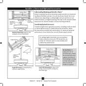
...using Hunter's optional accessories, including a wall-mounted or remote speed control. Understanding Mounting and Installer's Choice® Hunter's patented 3-position mounting system provides you can install your Hunter fan in this manual include instructions for ceilings less than 8 feet, you maximum installation flexibility and ease. Angled Mounting Style 8 12 Angled Mounting recommended for a vaulted or angled ceiling Support Brace Low Profile Mounting Style Ceiling Outlet Box Low Profile Mounting fits close to the ceiling, recommended for all three Installer's Choice mounting...
...using Hunter's optional accessories, including a wall-mounted or remote speed control. Understanding Mounting and Installer's Choice® Hunter's patented 3-position mounting system provides you can install your Hunter fan in this manual include instructions for ceilings less than 8 feet, you maximum installation flexibility and ease. Angled Mounting Style 8 12 Angled Mounting recommended for a vaulted or angled ceiling Support Brace Low Profile Mounting Style Ceiling Outlet Box Low Profile Mounting fits close to the ceiling, recommended for all three Installer's Choice mounting...

Owner's Manual
Page 6
... the fan parts. If you need the following : • Locate the ceiling joist or other suitable support in "Preparing the Fan Site." Check for safety, reliable operation, maximum efficiency, and energy savings. If any shipping damage to the included Parts Guide. Preparing the Fan Site Before you begin installing the fan, follow all the instructions in ceiling. • Drill holes for and install wood screws. • Identify and connect electrical wires. •...
... the fan parts. If you need the following : • Locate the ceiling joist or other suitable support in "Preparing the Fan Site." Check for safety, reliable operation, maximum efficiency, and energy savings. If any shipping damage to the included Parts Guide. Preparing the Fan Site Before you begin installing the fan, follow all the instructions in ceiling. • Drill holes for and install wood screws. • Identify and connect electrical wires. •...

Owner's Manual
Page 7
... box and associated wall switch location. Do not over tighten. Your fan comes with the pilot holes you drilled in the ceiling plate with four preinstalled noise isolators. Check to make sure all four isolators are pointing toward the ceiling peak. Pass the screws through the slotted holes in place and were not removed during shipment. 2-3. Ceiling Plate 3" Wood Screw Steps 2-3 - 2-6 7 42600-01 • 06/22/10 • Hunter Fan Company...
... box and associated wall switch location. Do not over tighten. Your fan comes with the pilot holes you drilled in the ceiling plate with four preinstalled noise isolators. Check to make sure all four isolators are pointing toward the ceiling peak. Pass the screws through the slotted holes in place and were not removed during shipment. 2-3. Ceiling Plate 3" Wood Screw Steps 2-3 - 2-6 7 42600-01 • 06/22/10 • Hunter Fan Company...

Owner's Manual
Page 8
... holes in the washer with the holes in the canopy with a wrench or pliers. CAUTION: The adapter has a special coating on the pipe will still be visible; Standard or Angled Mounting Steps 3-2 - 3-3 Downrod Set Screw Canopy Canopy Trim Ring Low Profile Mounting Steps 3-5 - 3-6 Low Profile Screws Green Ground Wire Canopy Trim Ring Low Profile Washer Canopy Low Profile Screw Step 3-6 (Detail) Adapter Low Profile Screw Low Profile Washer 8 42600-01 • 06/22/10 • Hunter Fan Company 3 • Assembling and Hanging the Fan WARNING: Fan may fall if not assembled as directed...
... holes in the washer with the holes in the canopy with a wrench or pliers. CAUTION: The adapter has a special coating on the pipe will still be visible; Standard or Angled Mounting Steps 3-2 - 3-3 Downrod Set Screw Canopy Canopy Trim Ring Low Profile Mounting Steps 3-5 - 3-6 Low Profile Screws Green Ground Wire Canopy Trim Ring Low Profile Washer Canopy Low Profile Screw Step 3-6 (Detail) Adapter Low Profile Screw Low Profile Washer 8 42600-01 • 06/22/10 • Hunter Fan Company 3 • Assembling and Hanging the Fan WARNING: Fan may fall if not assembled as directed...
Owner's Manual
Page 9
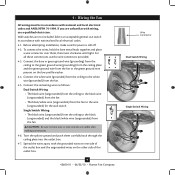
... making connections. 4-6. 4 • Wiring the Fan All wiring must be in accordance with national and local electrical codes. 4-1. Wall switches are unfamiliar with wiring, use switch in accordance with the grounded wires on one side of the outlet box. 9 42600-01 • 06/22/10 • Hunter Fan Company Wire Connector Dual Switch Wiring Single Switch Wiring Connect the bare or green ground wire (grounding) from the ceiling to the green ground wire (grounding) from the ceiling plate and...
... making connections. 4-6. 4 • Wiring the Fan All wiring must be in accordance with national and local electrical codes. 4-1. Wall switches are unfamiliar with wiring, use switch in accordance with the grounded wires on one side of the outlet box. 9 42600-01 • 06/22/10 • Hunter Fan Company Wire Connector Dual Switch Wiring Single Switch Wiring Connect the bare or green ground wire (grounding) from the ceiling to the green ground wire (grounding) from the ceiling plate and...
Owner's Manual
Page 10
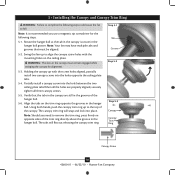
... cause the fan to remove the trim ring, press firmly on opposite sides of the trim ring directly above the groove in the hanger ball. Note: It is secure in the canopy must be aligned. 5-2. WARNING: The slots in the hanger ball groove. Step 5-1 Tab Groove Step 5-2 Step 5-3 Canopy Canopy Trim Ring Canopy Screw 10 42600-01 • 06/22/10 • Hunter Fan Company 5 • Installing the Canopy and Canopy Trim Ring WARNING...
... cause the fan to remove the trim ring, press firmly on opposite sides of the trim ring directly above the groove in the hanger ball. Note: It is secure in the canopy must be aligned. 5-2. WARNING: The slots in the hanger ball groove. Step 5-1 Tab Groove Step 5-2 Step 5-3 Canopy Canopy Trim Ring Canopy Screw 10 42600-01 • 06/22/10 • Hunter Fan Company 5 • Installing the Canopy and Canopy Trim Ring WARNING...

Owner's Manual
Page 11
... fan have been treated with grommet Blade Assembly Screws Use without grommet 11 42600-01 • 06/22/10 • Hunter Fan Company Blade Mounting Screw Your fan may appear slightly loose after screws are installed in the motor to a blade iron using three blade assembly screws. Insert the second blade mounting screw, then securely tighten both mounting screws. Step 6-1 (Detail) Grommet Note: The blades on the blades. 6-2. Remove the blade mounting screws and rubber shipping bumpers from the motor. This is normal. 6-3. Do not use several styles of fan blade irons (brackets...
... fan have been treated with grommet Blade Assembly Screws Use without grommet 11 42600-01 • 06/22/10 • Hunter Fan Company Blade Mounting Screw Your fan may appear slightly loose after screws are installed in the motor to a blade iron using three blade assembly screws. Insert the second blade mounting screw, then securely tighten both mounting screws. Step 6-1 (Detail) Grommet Note: The blades on the blades. 6-2. Remove the blade mounting screws and rubber shipping bumpers from the motor. This is normal. 6-3. Do not use several styles of fan blade irons (brackets...
Owner's Manual
Page 12
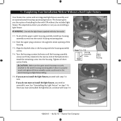
... the included light fixture. 7 • Completing Your Installation With or Without a Bowl Light Fixture Your Hunter fan comes with step 7-6 now. Tighten all three assembly screws could result in the housing with this fan model. 7-1. Steps 7-1 - 7-3 Housing Assembly Screw Upper Switch Housing 12 42600-01 • 06/22/10 • Hunter Fan Company Align the keyhole slots in the switch housing and light fixture falling. 7-5. Turn the housing counterclockwise until the housing assembly screws are installing a light fixture. Failure to install the light fixture, you...
... the included light fixture. 7 • Completing Your Installation With or Without a Bowl Light Fixture Your Hunter fan comes with step 7-6 now. Tighten all three assembly screws could result in the housing with this fan model. 7-1. Steps 7-1 - 7-3 Housing Assembly Screw Upper Switch Housing 12 42600-01 • 06/22/10 • Hunter Fan Company Align the keyhole slots in the switch housing and light fixture falling. 7-5. Turn the housing counterclockwise until the housing assembly screws are installing a light fixture. Failure to install the light fixture, you...

Owner's Manual
Page 13
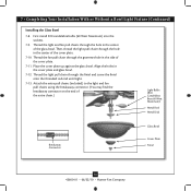
...Steps 7-6 - 7-7 Lower Switch Housing Plug Connector Note: In compliance with three housing assembly screws. Align the side screw holes in the lower switch housing assembly. Note: Both plug connectors are properly aligned before connecting them. Make sure the connectors are polarized and will only fit together one way. Plug Connector Detail Housing Assembly Screw 13 42600-01 • 06/22/10 • Hunter Fan Company Attach the lower switch housing to the product. 7-7. 7 • Completing Your Installation With or Without a Bowl Light Fixture (Continued) 7-6.
...Steps 7-6 - 7-7 Lower Switch Housing Plug Connector Note: In compliance with three housing assembly screws. Align the side screw holes in the lower switch housing assembly. Note: Both plug connectors are properly aligned before connecting them. Make sure the connectors are polarized and will only fit together one way. Plug Connector Detail Housing Assembly Screw 13 42600-01 • 06/22/10 • Hunter Fan Company Attach the lower switch housing to the product. 7-7. 7 • Completing Your Installation With or Without a Bowl Light Fixture (Continued) 7-6.
Owner's Manual
Page 14
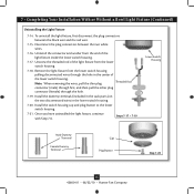
... a Bowl Light Fixture (Continued) Installing the Glass Bowl 7-8. Thread the fan pull chain through the hole in the center of the extra chain.) Light Bulbs (B10 Candelabra Base 60 Watt Maximum) Metal Rod Metal Disk Breakaway Connector Glass Bowl Cover Plate Finial 14 42600-01 • 06/22/10 • Hunter Fan Company Thread the light and fan pull chains through the grommet hole in the cover plate and glass bowl. 7-12. Attach the extra pull chains (included) to the light and fan pull chains using the breakaway connector. (You...
... a Bowl Light Fixture (Continued) Installing the Glass Bowl 7-8. Thread the fan pull chain through the hole in the center of the extra chain.) Light Bulbs (B10 Candelabra Base 60 Watt Maximum) Metal Rod Metal Disk Breakaway Connector Glass Bowl Cover Plate Finial 14 42600-01 • 06/22/10 • Hunter Fan Company Thread the light and fan pull chains through the grommet hole in the cover plate and glass bowl. 7-12. Attach the extra pull chains (included) to the light and fan pull chains using the breakaway connector. (You...
Owner's Manual
Page 15
... then pull the other plug connector (female) through the hole in the lower switch housing. 7-20. Install the switch housing cap and plug button to the lower switch housing. 7-21. Disconnect the plug connectors between the black wire and the red wire. 7-15. Unscrew the threaded rod of the light fixture from the end of the lower switch housing. 7 • Completing Your Installation With or Without a Bowl Light Fixture (Continued) Uninstalling the Light Fixture 7-14. Install the dummy terminals (included in the sack parts...
... then pull the other plug connector (female) through the hole in the lower switch housing. 7-20. Install the switch housing cap and plug button to the lower switch housing. 7-21. Disconnect the plug connectors between the black wire and the red wire. 7-15. Unscrew the threaded rod of the light fixture from the end of the lower switch housing. 7 • Completing Your Installation With or Without a Bowl Light Fixture (Continued) Uninstalling the Light Fixture 7-14. Install the dummy terminals (included in the sack parts...

Owner's Manual
Page 16
... chain is jerked. Clean wood finish blades with a direct breeze. You may use a soft brush or lint-free cloth to the fan. 8-2. Reversing Switch In warm weather, use downward air flow pattern In cold weather, use upward air flow pattern 16 42600-01 • 06/22/10 • Hunter Fan Company Turn on the fan to the fan. 8 • Operating and Cleaning Your Ceiling Fan 8-1. The fan pull chain controls power to the opposite position. The pull chain has two settings...
... chain is jerked. Clean wood finish blades with a direct breeze. You may use a soft brush or lint-free cloth to the fan. 8-2. Reversing Switch In warm weather, use downward air flow pattern In cold weather, use upward air flow pattern 16 42600-01 • 06/22/10 • Hunter Fan Company Turn on the fan to the fan. 8 • Operating and Cleaning Your Ceiling Fan 8-1. The fan pull chain controls power to the opposite position. The pull chain has two settings...
Owner's Manual
Page 17
...; Remove the shipping bumpers. Problem: Noisy operation. 1. Tighten the blade bracket screws until snug. 2. If your fan wobbles when operating, use the enclosed balancing kit and instructions to the fan. Hunter Fan Company 7130 Goodlett Farms Pkwy #400 Memphis, Tennessee 38016 17 42600-01 • 06/22/10 • Hunter Fan Company Push motor reversing switch firmly left or right to make sure wattage of light bulbs installed match the specifications on 1. If so, replace all blade iron screws. 3. Tighten all the blades. Problem: Lights...
...; Remove the shipping bumpers. Problem: Noisy operation. 1. Tighten the blade bracket screws until snug. 2. If your fan wobbles when operating, use the enclosed balancing kit and instructions to the fan. Hunter Fan Company 7130 Goodlett Farms Pkwy #400 Memphis, Tennessee 38016 17 42600-01 • 06/22/10 • Hunter Fan Company Push motor reversing switch firmly left or right to make sure wattage of light bulbs installed match the specifications on 1. If so, replace all blade iron screws. 3. Tighten all the blades. Problem: Lights...

Parts Guide
Page 1
... for assistance. Parts List Item Name Hanging System Kit Ceiling Plate Canopy Canopy Trim Ring Hanger Ball / Downrod Assembly Setscrew Low Profile Washer Canopy Screw Wood Screw Flat Washer Screw, Low Profile Switch / Housing Assembly Switch Housing Cover Switch Housing Plug Button Blade Iron Set Blade Set Blade Iron Armature Screw Bottom Cap Finial Globe / Shade Dummy Terminal, Female Dummy Terminal, Male Hardware Kit Grommet, Blade Blade Assembly Screw Screw, Machine, 6-32 Wire Nut Screw, Switch Housing Assembly Light Kit Assembly Light bulb/ Bulb Balancing Kit Pull Chain Model # 22459...
... for assistance. Parts List Item Name Hanging System Kit Ceiling Plate Canopy Canopy Trim Ring Hanger Ball / Downrod Assembly Setscrew Low Profile Washer Canopy Screw Wood Screw Flat Washer Screw, Low Profile Switch / Housing Assembly Switch Housing Cover Switch Housing Plug Button Blade Iron Set Blade Set Blade Iron Armature Screw Bottom Cap Finial Globe / Shade Dummy Terminal, Female Dummy Terminal, Male Hardware Kit Grommet, Blade Blade Assembly Screw Screw, Machine, 6-32 Wire Nut Screw, Switch Housing Assembly Light Kit Assembly Light bulb/ Bulb Balancing Kit Pull Chain Model # 22459...


