
Installation Guide
Page 1
... UL-approved octagonal 4" x 1-1/2" outlet box • Two #8 x 1-1/2" wood screws and washers • Approved connector for electrical wire Checklist for your new Hunter fan. If NOT, install a support brace as a tag, to install the support brace and outlet box. Obtain a UL-approved octagonal 4" x 1-1/2" outlet box,... manufacturer). o Six inches of the ceiling. If your fan manual and begin with 2 • Installing the Ceiling Plate. Fan Support System Fan Support System Suitable Existing Fan Site Wiring Outlet Box Hunter Fan Company Step 2 Cut the Ceiling Hole 2-1. Cut a ...
... UL-approved octagonal 4" x 1-1/2" outlet box • Two #8 x 1-1/2" wood screws and washers • Approved connector for electrical wire Checklist for your new Hunter fan. If NOT, install a support brace as a tag, to install the support brace and outlet box. Obtain a UL-approved octagonal 4" x 1-1/2" outlet box,... manufacturer). o Six inches of the ceiling. If your fan manual and begin with 2 • Installing the Ceiling Plate. Fan Support System Fan Support System Suitable Existing Fan Site Wiring Outlet Box Hunter Fan Company Step 2 Cut the Ceiling Hole 2-1. Cut a ...

Owner's Manual
Page 1
Model Name Model No. Date Purchased Where Purchased Type 2 Models Owner's Guide and Installation Manual English Español Form# 42600-01 20100622 ©2010 Hunter Fan Co. For Your Records and Warranty Assistance For reference, also attach your receipt or a copy of your receipt to the manual.
Model Name Model No. Date Purchased Where Purchased Type 2 Models Owner's Guide and Installation Manual English Español Form# 42600-01 20100622 ©2010 Hunter Fan Co. For Your Records and Warranty Assistance For reference, also attach your receipt or a copy of your receipt to the manual.
Owner's Manual
Page 2
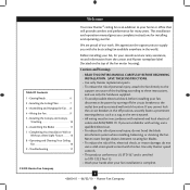
... by turning off position, securely fasten a prominent warning device, such as a tag, to your fan. Welcome Your new Hunter® ceiling fan is complete. © 2010 Hunter Fan Company 2 42600-01 • 06/22/10 • Hunter Fan Company SAVE THESE INSTRUCTIONS. • Use only Hunter replacement parts. • To reduce the risk of personal injury, attach the...
... by turning off position, securely fasten a prominent warning device, such as a tag, to your fan. Welcome Your new Hunter® ceiling fan is complete. © 2010 Hunter Fan Company 2 42600-01 • 06/22/10 • Hunter Fan Company SAVE THESE INSTRUCTIONS. • Use only Hunter replacement parts. • To reduce the risk of personal injury, attach the...

Owner's Manual
Page 3
...is an UL-approved octagonal 4" x 1-1/2" outlet box (or as described on this page. Fan Support System Fan Support System Suitable Existing Fan Site Wiring Outlet Box 3 42600-01 • 06/22/10 • Hunter Fan Company Ceiling Hole • The outlet box clearance hole is suitable, skip ahead to the ...through the inner holes of outlet box. • The outer holes of the fan blade tips. • The fan is directly below the joist or support brace. If your new Hunter fan. Preparing the Fan Site Step 1 - Choose a fan site where: • No object can come in contact with the rotating...
...is an UL-approved octagonal 4" x 1-1/2" outlet box (or as described on this page. Fan Support System Fan Support System Suitable Existing Fan Site Wiring Outlet Box 3 42600-01 • 06/22/10 • Hunter Fan Company Ceiling Hole • The outlet box clearance hole is suitable, skip ahead to the ...through the inner holes of outlet box. • The outer holes of the fan blade tips. • The fan is directly below the joist or support brace. If your new Hunter fan. Preparing the Fan Site Step 1 - Choose a fan site where: • No object can come in contact with the rotating...

Owner's Manual
Page 4
... . If you to allow you are turned off position, securely fasten a prominent warning device, such as follows: 3-1. You will hold the outlet box and fan. 2-2. Obtain a UL-approved octagonal 4" x 1-1/2" outlet box, plus two #8 x 1-1/2" wood screws and washers, available from any hardware store or electrical supply...screws (5/64") through the outlet box so that will use a qualified electrician. 4 42600-01 • 06/22/10 • Hunter Fan Company Make sure the circuit breakers to install the support brace and outlet box. Cut the Ceiling Hole 2-1. Steps 2 - 3 3-2. Step 5 ...
... . If you to allow you are turned off position, securely fasten a prominent warning device, such as follows: 3-1. You will hold the outlet box and fan. 2-2. Obtain a UL-approved octagonal 4" x 1-1/2" outlet box, plus two #8 x 1-1/2" wood screws and washers, available from any hardware store or electrical supply...screws (5/64") through the outlet box so that will use a qualified electrician. 4 42600-01 • 06/22/10 • Hunter Fan Company Make sure the circuit breakers to install the support brace and outlet box. Cut the Ceiling Hole 2-1. Steps 2 - 3 3-2. Step 5 ...
Owner's Manual
Page 5
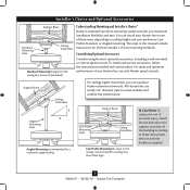
...reduce the risk of personal injury, attach the fan directly to assure stability and wobble-free performance. Understanding Mounting and Installer's Choice® Hunter's patented 3-position mounting system provides you can install your Hunter fan in this manual include instructions for ceilings less ...use sturdy 3/4" diameter pipe to the support structure of your preference: Low Profile, Standard, or Angled mounting. All Hunter fans use the accessories, follow the instructions included with each product. Installer's Choice and Optional Accessories Support Brace Standard Mounting ...
...reduce the risk of personal injury, attach the fan directly to assure stability and wobble-free performance. Understanding Mounting and Installer's Choice® Hunter's patented 3-position mounting system provides you can install your Hunter fan in this manual include instructions for ceilings less ...use sturdy 3/4" diameter pipe to the support structure of your preference: Low Profile, Standard, or Angled mounting. All Hunter fans use the accessories, follow the instructions included with each product. Installer's Choice and Optional Accessories Support Brace Standard Mounting ...

Owner's Manual
Page 6
...they were shipped. 6 42600-01 • 06/22/10 • Hunter Fan Company Gathering the Tools You will need help installing the fan, your Hunter fan dealer can direct you can do the following tools for installing the fan: • Electric drill with 9/64" bit • Standard screwdriver (... (magnetic tip recommended) • Wrench or pliers • Ladder (height dependent upon installation site) Checking Your Fan Parts Carefully unpack your Hunter dealer or call Hunter Technical Support Department at 888-830-1326 (In Canada, call 1-866-268-1936). Check for any parts are essential...
...they were shipped. 6 42600-01 • 06/22/10 • Hunter Fan Company Gathering the Tools You will need help installing the fan, your Hunter fan dealer can direct you can do the following tools for installing the fan: • Electric drill with 9/64" bit • Standard screwdriver (... (magnetic tip recommended) • Wrench or pliers • Ladder (height dependent upon installation site) Checking Your Fan Parts Carefully unpack your Hunter dealer or call Hunter Technical Support Department at 888-830-1326 (In Canada, call 1-866-268-1936). Check for any parts are essential...

Owner's Manual
Page 7
... in the wood support structure. Ceiling Plate 3" Wood Screw Steps 2-3 - 2-6 7 42600-01 • 06/22/10 • Hunter Fan Company Your fan comes with the pilot holes you drilled in the outlet box. For Angled Ceilings: Be sure to orient the ceiling plate so that the... the outlet box and associated wall switch location. 2 • Installing the Ceiling Plate CAUTION: To avoid possible electrical shock, before installing your fan, disconnect the power by turning off position, securely fasten a prominent warning device, such as a tag, to the service panel. 2-1. Do not...
... in the wood support structure. Ceiling Plate 3" Wood Screw Steps 2-3 - 2-6 7 42600-01 • 06/22/10 • Hunter Fan Company Your fan comes with the pilot holes you drilled in the outlet box. For Angled Ceilings: Be sure to orient the ceiling plate so that the... the outlet box and associated wall switch location. 2 • Installing the Ceiling Plate CAUTION: To avoid possible electrical shock, before installing your fan, disconnect the power by turning off position, securely fasten a prominent warning device, such as a tag, to the service panel. 2-1. Do not...

Owner's Manual
Page 8
...Profile Washer Canopy Low Profile Screw Step 3-6 (Detail) Adapter Low Profile Screw Low Profile Washer 8 42600-01 • 06/22/10 • Hunter Fan Company For Standard or Angled mounting: 3-2. Do not remove this is fully installed, 2-3 threads on the ceiling plate. 3-8. Remove the set screw from ...the fan through the canopy and canopy trim ring. Hanging the Fan: Note: To hang the fan, you must tilt the canopy to step 3-7. Place the slots over the hooks to install the pipe and...
...Profile Washer Canopy Low Profile Screw Step 3-6 (Detail) Adapter Low Profile Screw Low Profile Washer 8 42600-01 • 06/22/10 • Hunter Fan Company For Standard or Angled mounting: 3-2. Do not remove this is fully installed, 2-3 threads on the ceiling plate. 3-8. Remove the set screw from ...the fan through the canopy and canopy trim ring. Hanging the Fan: Note: To hang the fan, you must tilt the canopy to step 3-7. Place the slots over the hooks to install the pipe and...
Owner's Manual
Page 9
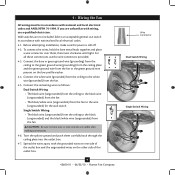
...splices upward and push them , then twist clockwise until tight. Before attempting installation, make sure the power is still off. 4-2. 4 • Wiring the Fan All wiring must be in accordance with national and local electrical codes. 4-1. To connect the wires, hold the bare metal leads together and place a wire...the wires apart, with the grounded wires on one side of the outlet box. 9 42600-01 • 06/22/10 • Hunter Fan Company Wire Connector Dual Switch Wiring Single Switch Wiring Connect the remaining wires as follows: Dual Switch Wiring: • The black wire (...
...splices upward and push them , then twist clockwise until tight. Before attempting installation, make sure the power is still off. 4-2. 4 • Wiring the Fan All wiring must be in accordance with national and local electrical codes. 4-1. To connect the wires, hold the bare metal leads together and place a wire...the wires apart, with the grounded wires on one side of the outlet box. 9 42600-01 • 06/22/10 • Hunter Fan Company Wire Connector Dual Switch Wiring Single Switch Wiring Connect the remaining wires as follows: Dual Switch Wiring: • The black wire (...
Owner's Manual
Page 10
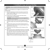
... mounting holes on the ceiling plate. Verify that must remain engaged while swinging the canopy for the following steps could cause the fan to align the canopy screw holes with the screw holes aligned, partially install two canopy screws into the holes opposite the ceiling plate... for alignment. 5-3. Step 5-1 Tab Groove Step 5-2 Step 5-3 Canopy Canopy Trim Ring Canopy Screw 10 42600-01 • 06/22/10 • Hunter Fan Company 5 • Installing the Canopy and Canopy Trim Ring WARNING: Failure to complete the following steps. 5-1. Note: It is secure in the hanger ball...
... mounting holes on the ceiling plate. Verify that must remain engaged while swinging the canopy for the following steps could cause the fan to align the canopy screw holes with the screw holes aligned, partially install two canopy screws into the holes opposite the ceiling plate... for alignment. 5-3. Step 5-1 Tab Groove Step 5-2 Step 5-3 Canopy Canopy Trim Ring Canopy Screw 10 42600-01 • 06/22/10 • Hunter Fan Company 5 • Installing the Canopy and Canopy Trim Ring WARNING: Failure to complete the following steps. 5-1. Note: It is secure in the hanger ball...

Owner's Manual
Page 11
... in the motor to secure shipping blocks. 6-4. This is normal. 6-3. Do not use several styles of fan blade irons (brackets that leave any other cleaners that hold the blade to the fan). 6-1. 6 • Assembling the Blades Hunter fans use a furniture polish or any residue, as they will damage the protective Dust Armor on the...
... in the motor to secure shipping blocks. 6-4. This is normal. 6-3. Do not use several styles of fan blade irons (brackets that leave any other cleaners that hold the blade to the fan). 6-1. 6 • Assembling the Blades Hunter fans use a furniture polish or any residue, as they will damage the protective Dust Armor on the...
Owner's Manual
Page 12
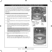
...tighten all three screws firmly. Steps 7-1 - 7-3 Housing Assembly Screw Upper Switch Housing 12 42600-01 • 06/22/10 • Hunter Fan Company Tighten all three assembly screws could result in the housing with step 7-6 now. See "Uninstalling the Light Fixture" on step 7-14...remaining screw into the switch housing mounting plate. 7-2. 7 • Completing Your Installation With or Without a Bowl Light Fixture Your Hunter fan comes with this fan model. 7-1. This feature gives you the option of the keyhole slots. Feed the upper plug connector through the center opening of ...
...tighten all three screws firmly. Steps 7-1 - 7-3 Housing Assembly Screw Upper Switch Housing 12 42600-01 • 06/22/10 • Hunter Fan Company Tighten all three assembly screws could result in the housing with step 7-6 now. See "Uninstalling the Light Fixture" on step 7-14...remaining screw into the switch housing mounting plate. 7-2. 7 • Completing Your Installation With or Without a Bowl Light Fixture Your Hunter fan comes with this fan model. 7-1. This feature gives you the option of the keyhole slots. Feed the upper plug connector through the center opening of ...

Owner's Manual
Page 13
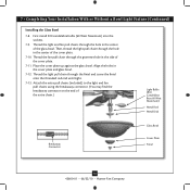
... them. Incorrect connection could cause improper operation and damage to the upper switch housing with US federal energy regulations, this ceiling fan contains a device that limit or the marked limit on this product may result in fire hazard or improper operation. Place the...side screw holes in the lower switch housing assembly. Plug Connector Detail Housing Assembly Screw 13 42600-01 • 06/22/10 • Hunter Fan Company 7 • Completing Your Installation With or Without a Bowl Light Fixture (Continued) 7-6. Exceeding that restricts the light kit to the ...
... them. Incorrect connection could cause improper operation and damage to the upper switch housing with US federal energy regulations, this ceiling fan contains a device that limit or the marked limit on this product may result in fire hazard or improper operation. Place the...side screw holes in the lower switch housing assembly. Plug Connector Detail Housing Assembly Screw 13 42600-01 • 06/22/10 • Hunter Fan Company 7 • Completing Your Installation With or Without a Bowl Light Fixture (Continued) 7-6. Exceeding that restricts the light kit to the ...
Owner's Manual
Page 14
...Metal Rod Metal Disk Breakaway Connector Glass Bowl Cover Plate Finial 14 42600-01 • 06/22/10 • Hunter Fan Company Attach the extra pull chains (included) to the light and fan pull chains using the breakaway connector. (You may find the breakaway connector on the end of the cover plate. 7-...10. Place the cover plate up against the glass bowl. First install B10 candelabra bulbs (60 Watt Maximum) into the sockets. 7-9. Thread the fan pull chain through the hole in the side of the glass bowl. Align the holes in the center of the cover plate. 7-11. Thread the...
...Metal Rod Metal Disk Breakaway Connector Glass Bowl Cover Plate Finial 14 42600-01 • 06/22/10 • Hunter Fan Company Attach the extra pull chains (included) to the light and fan pull chains using the breakaway connector. (You may find the breakaway connector on the end of the cover plate. 7-...10. Place the cover plate up against the glass bowl. First install B10 candelabra bulbs (60 Watt Maximum) into the sockets. 7-9. Thread the fan pull chain through the hole in the side of the glass bowl. Align the holes in the center of the cover plate. 7-11. Thread the...
Owner's Manual
Page 15
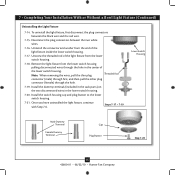
.... Steps 7-17 - 7-19 Lower Switch Housing Male Dummy Terminal Female Dummy Terminal Cap Plug Button Step 7-20 15 42600-01 • 06/22/10 • Hunter Fan Company Remove the light fixture from the lower switch housing pulling disconnected wires through the hole. 7-19. Unscrew the threaded rod of the light fixture...
.... Steps 7-17 - 7-19 Lower Switch Housing Male Dummy Terminal Female Dummy Terminal Cap Plug Button Step 7-20 15 42600-01 • 06/22/10 • Hunter Fan Company Remove the light fixture from the lower switch housing pulling disconnected wires through the hole. 7-19. Unscrew the threaded rod of the light fixture...

Owner's Manual
Page 16
Turn on the fan to the light. The pull chain has two settings: On and Off. 8-4. A vacuum cleaner brush nozzle can remove heavier dust. You may use upward air flow pattern 16 42600-01 • 06/22/10 • Hunter Fan Company To Change Airflow Direction Turn the fan off and let it ...come to the fan. 8-2. Slide the reversing switch on electrical power to a complete stop. In winter, having the...
Turn on the fan to the light. The pull chain has two settings: On and Off. 8-4. A vacuum cleaner brush nozzle can remove heavier dust. You may use upward air flow pattern 16 42600-01 • 06/22/10 • Hunter Fan Company To Change Airflow Direction Turn the fan off and let it ...come to the fan. 8-2. Slide the reversing switch on electrical power to a complete stop. In winter, having the...
Owner's Manual
Page 17
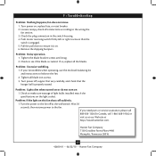
... switch housing. 4. Tighten the blade bracket screws until snug. 2. If so, replace all blade iron screws. 3. Hunter Fan Company 7130 Goodlett Farms Pkwy #400 Memphis, Tennessee 38016 17 42600-01 • 06/22/10 • Hunter Fan Company Problem: Lights dim when turned on or do not turn on , replace fuse, or reset breaker...
... switch housing. 4. Tighten the blade bracket screws until snug. 2. If so, replace all blade iron screws. 3. Hunter Fan Company 7130 Goodlett Farms Pkwy #400 Memphis, Tennessee 38016 17 42600-01 • 06/22/10 • Hunter Fan Company Problem: Lights dim when turned on or do not turn on , replace fuse, or reset breaker...

Parts Guide
Page 1
... Bronze Part # 96759-30 Brushed Nickel Part # 96759-09 22461 94344-03 White Part # 96759-03 22462 94344-04 White Part # 96759-03-000 1 G0655-30 G0655-09 G0655-03 G0655-03 1 73853-...77646-04 1 07570-01 07570-01 07570-01 07570-01 1 63756-05 63756-05 63756-05 63756-05 Hunter Fan Company • 7130 Goodlett Farms Pkwy. #400 • Memphis, TN 38016 • www.hunterfan.com...Screw, Switch Housing Assembly Screw, Machine, 6-32 Hanger Bracket Assembly Blade Assembly Switch Housing Assembly Fan Parts (Not Drawn to Scale) PARTS GUIDE Using this Parts Guide, make sure all parts ...
... Bronze Part # 96759-30 Brushed Nickel Part # 96759-09 22461 94344-03 White Part # 96759-03 22462 94344-04 White Part # 96759-03-000 1 G0655-30 G0655-09 G0655-03 G0655-03 1 73853-...77646-04 1 07570-01 07570-01 07570-01 07570-01 1 63756-05 63756-05 63756-05 63756-05 Hunter Fan Company • 7130 Goodlett Farms Pkwy. #400 • Memphis, TN 38016 • www.hunterfan.com...Screw, Switch Housing Assembly Screw, Machine, 6-32 Hanger Bracket Assembly Blade Assembly Switch Housing Assembly Fan Parts (Not Drawn to Scale) PARTS GUIDE Using this Parts Guide, make sure all parts ...


