
Installation Guide
Page 1
... connector, available at least 8 feet high. • e fan blades have now successfully prepared your new Hunter fan. o e outlet box is secured to the joist or support brace by wood screws and washers through the inner holes of outlet box. Wiring o e electrical cable is secured to outlet box by the support brace manufacturer). Steps 2 - 3 Step 3 Install a Support Brace, If Necessary Determine if there is a ceiling joist directly above the floor...
... connector, available at least 8 feet high. • e fan blades have now successfully prepared your new Hunter fan. o e outlet box is secured to the joist or support brace by wood screws and washers through the inner holes of outlet box. Wiring o e electrical cable is secured to outlet box by the support brace manufacturer). Steps 2 - 3 Step 3 Install a Support Brace, If Necessary Determine if there is a ceiling joist directly above the floor...

Owner's Manual
Page 1
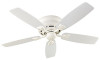
For Your Records and Warranty Assistance For reference, also attach your receipt or a copy of your receipt to the manual. _S_e_a_W__i_n_d Model Name _2_3_3_4_7 Model No. Date Purchased Where Purchased Model Type 7 Owner's Guide and Installation Manual English Español Form# 42843-01 20081216 ©2008 Hunter Fan Co.
For Your Records and Warranty Assistance For reference, also attach your receipt or a copy of your receipt to the manual. _S_e_a_W__i_n_d Model Name _2_3_3_4_7 Model No. Date Purchased Where Purchased Model Type 7 Owner's Guide and Installation Manual English Español Form# 42843-01 20081216 ©2008 Hunter Fan Co.

Owner's Manual
Page 2
... system when installing, balancing, or cleaning the fan. Use only Hunter speed controls. © 2008 Hunter Fan Company 2 42843-01 • 12/16/08 • Hunter Fan Company Table Of Contents 1 • Getting Ready 4 2 • Installing the Hanger Bracket 5 3 • Assembling and Hanging the Fan . . . 6 4 •Wiring the Fan 7 5 • Installing the Motor Housing 8 6 • Assembling the Blades 9 7 • Installing the Switch Housing 10 8 • Operating and Cleaning Your Ceiling Fan 11 9 • Troubleshooting 12 Welcome Your new Hunter® ceiling fan is an...
... system when installing, balancing, or cleaning the fan. Use only Hunter speed controls. © 2008 Hunter Fan Company 2 42843-01 • 12/16/08 • Hunter Fan Company Table Of Contents 1 • Getting Ready 4 2 • Installing the Hanger Bracket 5 3 • Assembling and Hanging the Fan . . . 6 4 •Wiring the Fan 7 5 • Installing the Motor Housing 8 6 • Assembling the Blades 9 7 • Installing the Switch Housing 10 8 • Operating and Cleaning Your Ceiling Fan 11 9 • Troubleshooting 12 Welcome Your new Hunter® ceiling fan is an...
Owner's Manual
Page 3
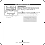
... on flat ceilings and can be used on ceilings less than 8 feet high Understanding Mounting Hunter's patented mounting system provides you maximum ease in installing your Hunter fan, use only Hunter speed controls. This fan was designed to these instructions, and use the accessories, follow the instructions included with each product. Considering Optional Accessories Consider using Hunter's optional accessories, including a wall-mounted or remote speed control. Mounting and Optional Accessories Support Brace Low Profile Mounting Style Ceiling Outlet Box Low Profile Mounting fits close...
... on flat ceilings and can be used on ceilings less than 8 feet high Understanding Mounting Hunter's patented mounting system provides you maximum ease in installing your Hunter fan, use only Hunter speed controls. This fan was designed to these instructions, and use the accessories, follow the instructions included with each product. Considering Optional Accessories Consider using Hunter's optional accessories, including a wall-mounted or remote speed control. Mounting and Optional Accessories Support Brace Low Profile Mounting Style Ceiling Outlet Box Low Profile Mounting fits close...
Owner's Manual
Page 4
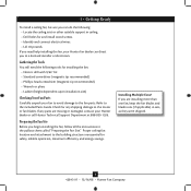
... fan blades and blade irons (if applicable) in ceiling. • Drill holes for safety, reliable operation, maximum efficiency, and energy savings. Check for any parts are essential for and install wood screws. • Identify and connect electrical wires. • Lift 40 pounds. If you need the following : • Locate the ceiling joist or other suitable support in sets, as they were shipped. 4 42843-01 • 12/16/08 • Hunter Fan Company...
... fan blades and blade irons (if applicable) in ceiling. • Drill holes for safety, reliable operation, maximum efficiency, and energy savings. Check for any parts are essential for and install wood screws. • Identify and connect electrical wires. • Lift 40 pounds. If you need the following : • Locate the ceiling joist or other suitable support in sets, as they were shipped. 4 42843-01 • 12/16/08 • Hunter Fan Company...

Owner's Manual
Page 5
... breakers to the outlet box and associated wall switch location. Partially install two canopy screws in the holes on each end of the hanger bracket. Thread the lead wires from the outlet box down through the slotted holes in the hanger bracket into the pilot holes you drilled in the wood support structure. do not use lubricants on the screws. Position the isolators between the hanger bracket and ceiling by turning off position...
... breakers to the outlet box and associated wall switch location. Partially install two canopy screws in the holes on each end of the hanger bracket. Thread the lead wires from the outlet box down through the slotted holes in the hanger bracket into the pilot holes you drilled in the wood support structure. do not use lubricants on the screws. Position the isolators between the hanger bracket and ceiling by turning off position...
Owner's Manual
Page 6
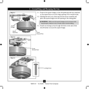
... result in the fan falling. 3-3. Install two locking screws through the holes in the metal bracket. 3-2. WARNING: Make sure the square hanger can not rotate in the ceiling plate. Green Ground Wire Step 3-3 Green Ground Wire #8-32 x 1" Screw Locking Screw 6 42843-01 • 12/16/08 • Hunter Fan Company Holding the wires out of the way, lift the motor assembly and place the square hanger into the opening...
... result in the fan falling. 3-3. Install two locking screws through the holes in the metal bracket. 3-2. WARNING: Make sure the square hanger can not rotate in the ceiling plate. Green Ground Wire Step 3-3 Green Ground Wire #8-32 x 1" Screw Locking Screw 6 42843-01 • 12/16/08 • Hunter Fan Company Holding the wires out of the way, lift the motor assembly and place the square hanger into the opening...
Owner's Manual
Page 7
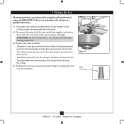
... the power by turning off the circuit breakers to the black/white wire from the fan to the outlet box and associated wall switch location. 4-2. Push all wires and wire connectors back through the ceiling plate hole into the outlet box. Step 4-3 Wire Connector 7 42843-01 • 12/16/08 • Hunter Fan Company 4 •Wiring the Fan All wiring must be in accordance with wiring, use a qualified electrician. 4-1. If you are visible after making connections. 4-3.
... the power by turning off the circuit breakers to the black/white wire from the fan to the outlet box and associated wall switch location. 4-2. Push all wires and wire connectors back through the ceiling plate hole into the outlet box. Step 4-3 Wire Connector 7 42843-01 • 12/16/08 • Hunter Fan Company 4 •Wiring the Fan All wiring must be in accordance with wiring, use a qualified electrician. 4-1. If you are visible after making connections. 4-3.
Owner's Manual
Page 8
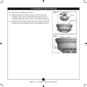
Place the fan housing over the motor. 5-2. 5 • Installing the Motor Housing 5-1. Align the keyholes in the fan housing with the two partially installed canopy screws in the narrow ends of the keyholes. 5-3. Step 5-1 Motor Fan Housing Step 5-3 Canopy Screw 8 42843-01 • 12/16/08 • Hunter Fan Company Rotate the fan housing to situate the screws in the hanger bracket. Install the two remaining canopy screws into the holes in the fan housing and into the hanger bracket. Securely tighten all screws.
Place the fan housing over the motor. 5-2. 5 • Installing the Motor Housing 5-1. Align the keyholes in the fan housing with the two partially installed canopy screws in the narrow ends of the keyholes. 5-3. Step 5-1 Motor Fan Housing Step 5-3 Canopy Screw 8 42843-01 • 12/16/08 • Hunter Fan Company Rotate the fan housing to situate the screws in the hanger bracket. Install the two remaining canopy screws into the holes in the fan housing and into the hanger bracket. Securely tighten all screws.

Owner's Manual
Page 9
...: Some blade mounting screws are tightened. Step 6-1 (Detail) Grommet Use with grommet Blade Assembly Screws Steps 6-1 - 6-2 Use without grommet Blade Mounting Screw Step 6-4 9 42843-01 • 12/16/08 • Hunter Fan Company Remove the blade mounting screws and rubber shipping bumpers from the motor. For each blade to the fan. Your fan may appear slightly loose after screws are installed in the motor to the fan). 6-1. Attach each blade, insert one blade mounting screw through the blade iron, and attach lightly to a blade iron using three blade assembly screws...
...: Some blade mounting screws are tightened. Step 6-1 (Detail) Grommet Use with grommet Blade Assembly Screws Steps 6-1 - 6-2 Use without grommet Blade Mounting Screw Step 6-4 9 42843-01 • 12/16/08 • Hunter Fan Company Remove the blade mounting screws and rubber shipping bumpers from the motor. For each blade to the fan. Your fan may appear slightly loose after screws are installed in the motor to the fan). 6-1. Attach each blade, insert one blade mounting screw through the blade iron, and attach lightly to a blade iron using three blade assembly screws...
Owner's Manual
Page 10
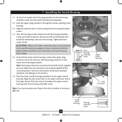
...housing assembly screws. Align the side screw holes in the housing with the housing assembly screws. 7-4. Align the keyhole slots in the upper and lower switch housings. Incorrect connection could result in the switch housing fixture falling. 7-5. Steps 7-1 - 7-4 Housing Assembly Screw Lower Switch Housing Housing Assembly Screw 10 42843-01 • 12/16/08 • Hunter Fan Company Upper Switch Housing Plug Connector Steps 7-5 - 7-6 Install the remaining screw into the switch housing mounting plate. 7-2. Place the lower switch housing assembly over the upper switch...
...housing assembly screws. Align the side screw holes in the housing with the housing assembly screws. 7-4. Align the keyhole slots in the upper and lower switch housings. Incorrect connection could result in the switch housing fixture falling. 7-5. Steps 7-1 - 7-4 Housing Assembly Screw Lower Switch Housing Housing Assembly Screw 10 42843-01 • 12/16/08 • Hunter Fan Company Upper Switch Housing Plug Connector Steps 7-5 - 7-6 Install the remaining screw into the switch housing mounting plate. 7-2. Place the lower switch housing assembly over the upper switch...
Owner's Manual
Page 11
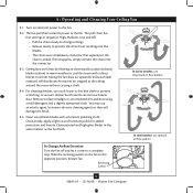
...; 12/16/08 • Hunter Fan Company 8 • Operating and Cleaning Your Ceiling Fan 8-1. A vacuum cleaner brush nozzle can remove heavier dust. Remove surface smudges or accumulated dirt and dust using a mild detergent and a slightly dampened cloth. Clean wood finish blades with a direct breeze. Turn on the fan to a complete stop. Occasionally, apply a light coat of furniture polish for added protection and beauty. The fan pull chain controls power to prevent scratching.
...; 12/16/08 • Hunter Fan Company 8 • Operating and Cleaning Your Ceiling Fan 8-1. A vacuum cleaner brush nozzle can remove heavier dust. Remove surface smudges or accumulated dirt and dust using a mild detergent and a slightly dampened cloth. Clean wood finish blades with a direct breeze. Turn on the fan to a complete stop. Occasionally, apply a light coat of furniture polish for added protection and beauty. The fan pull chain controls power to prevent scratching.
Owner's Manual
Page 12
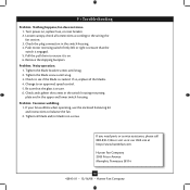
... shipping bumpers. Check to the wiring the fan section. 3. If so, replace all blade and/or blade iron screws. Loosen canopy, check all connections according to see if the blade is engaged. 5. Check and tighten the screws in the switch housing mounting plate and in the switch housing. 4. fan does not move. 1. Problem: Noisy operation. 1. 9 • Troubleshooting Problem: Nothing happens; Pull the pull chain to an approved speed control. 5. Change to ensure it is secure. 6. Problem: Excessive wobbling. 1. If you need parts or service...
... shipping bumpers. Check to the wiring the fan section. 3. If so, replace all blade and/or blade iron screws. Loosen canopy, check all connections according to see if the blade is engaged. 5. Check and tighten the screws in the switch housing mounting plate and in the switch housing. 4. fan does not move. 1. Problem: Noisy operation. 1. 9 • Troubleshooting Problem: Nothing happens; Pull the pull chain to an approved speed control. 5. Change to ensure it is secure. 6. Problem: Excessive wobbling. 1. If you need parts or service...
Parts Guide
Page 1
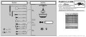
Parts List Item Name Ceiling Plate Housing Cover Screw Wood Screw Wood Screw Flat Washer Locking Screw Mounting Isolator Switch/Housing Assembly Blade Iron Set Blade Set Screw, Blade Iron Armature Hardware Kit Blade Grommet Blade Assembly Screw Screw, Machine, 6-32 Wire Connector Screw, Switch Housing Assembly Pull Chain Pull Chain Pendant Balancing Kit Model # 23347 Asm. REFER TO THE INSTALLATION MANUAL FOR FULL ASSEMBLY INSTRUCTIONS. Hardware (Drawn to Scale) x 2 x 4 x 2 x 2 x 4 x 4 Balancing x 1 Kit Wire x 4 Connector x 11 x 16 x 16 x 3 x 3 3" Wood Screw Flat Washer 1.5" ...
Parts List Item Name Ceiling Plate Housing Cover Screw Wood Screw Wood Screw Flat Washer Locking Screw Mounting Isolator Switch/Housing Assembly Blade Iron Set Blade Set Screw, Blade Iron Armature Hardware Kit Blade Grommet Blade Assembly Screw Screw, Machine, 6-32 Wire Connector Screw, Switch Housing Assembly Pull Chain Pull Chain Pendant Balancing Kit Model # 23347 Asm. REFER TO THE INSTALLATION MANUAL FOR FULL ASSEMBLY INSTRUCTIONS. Hardware (Drawn to Scale) x 2 x 4 x 2 x 2 x 4 x 4 Balancing x 1 Kit Wire x 4 Connector x 11 x 16 x 16 x 3 x 3 3" Wood Screw Flat Washer 1.5" ...


