
Installation Guide
Page 1
... Supplies You May Need • Drill • Keyhole saw • 2' x 4' support brace • UL-approved octagonal 4" x 1-1/2" outlet box • Two #8 x 1-1/2" wood screws and washers • Approved connector for electrical wire Checklist for your ceiling fan site. o Fan support system will hold full weight of the outlet box are aligned with joist or support brace. o e outer holes of the fan and light kit. o Six inches of the fan and light kit. If the...
... Supplies You May Need • Drill • Keyhole saw • 2' x 4' support brace • UL-approved octagonal 4" x 1-1/2" outlet box • Two #8 x 1-1/2" wood screws and washers • Approved connector for electrical wire Checklist for your ceiling fan site. o Fan support system will hold full weight of the outlet box are aligned with joist or support brace. o e outer holes of the fan and light kit. o Six inches of the fan and light kit. If the...

Owner's Manual
Page 28
Hunter Fan Company 2500 Frisco Avenue Memphis, TN 38114
Hunter Fan Company 2500 Frisco Avenue Memphis, TN 38114

Parts Guide
Page 1
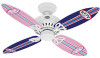
Blade Set Blade Grommet Screw, Blade Assembly Pull Chain Pull Chain Pendant (size and shape may vary) Parts List Model # Asm. Hunter Fan Company 2500 Frisco Avenue Memphis, Tennessee 38114 98000-01-819 10/30/2007 Dwg. # 23989 97970-01 Finish Flowers Item Name Blade Set Blade Grommet Blade Assembly Screw Pull Chain Pendant Pull Chain Pendant Pull Chain Qnty 1 1 1 2 Part # 88053-01 66011-01 66011-02 63756-25 23990 97970-02 Fairy Part # 88053-02 66012-02 66023-01 63756-25 23991 97970...
Blade Set Blade Grommet Screw, Blade Assembly Pull Chain Pull Chain Pendant (size and shape may vary) Parts List Model # Asm. Hunter Fan Company 2500 Frisco Avenue Memphis, Tennessee 38114 98000-01-819 10/30/2007 Dwg. # 23989 97970-01 Finish Flowers Item Name Blade Set Blade Grommet Blade Assembly Screw Pull Chain Pendant Pull Chain Pendant Pull Chain Qnty 1 1 1 2 Part # 88053-01 66011-01 66011-02 63756-25 23990 97970-02 Fairy Part # 88053-02 66012-02 66023-01 63756-25 23991 97970...

Owner's Manual
Page 1
Catalog No. Date Purchased Where Purchased Type 2 Models Owner's Guide and Installation Manual English Español Form# 41343-01 20081223 ©2008 Hunter Fan Co. Model Name Model No. For Your Records and Warranty Assistance For reference, also attach your receipt or a copy of your receipt to the manual.
Catalog No. Date Purchased Where Purchased Type 2 Models Owner's Guide and Installation Manual English Español Form# 41343-01 20081223 ©2008 Hunter Fan Co. Model Name Model No. For Your Records and Warranty Assistance For reference, also attach your receipt or a copy of your receipt to the manual.

Owner's Manual
Page 2
... supply you complete instructions for many years. Table of Contents 1 • Getting Ready 4 2 • Installing the Ceiling Plate 5 3 • Assembling the Fan 6 4 • Hanging and Wiring the Fan 7 5 • Installing the Canopy and Canopy Trim Ring 8 6 • Assembling the Blades 9 7 • Completing Your Installation With or Without a Light Fixture 10 8 • Operating the Remote Control _ and Mounting the Holder 12 9 • Operating and Cleaning Your Ceiling Fan 13 10 • Troubleshooting 14 Welcome Your new Hunter® ceiling fan is an addition...
... supply you complete instructions for many years. Table of Contents 1 • Getting Ready 4 2 • Installing the Ceiling Plate 5 3 • Assembling the Fan 6 4 • Hanging and Wiring the Fan 7 5 • Installing the Canopy and Canopy Trim Ring 8 6 • Assembling the Blades 9 7 • Completing Your Installation With or Without a Light Fixture 10 8 • Operating the Remote Control _ and Mounting the Holder 12 9 • Operating and Cleaning Your Ceiling Fan 13 10 • Troubleshooting 14 Welcome Your new Hunter® ceiling fan is an addition...

Owner's Manual
Page 3
...; Hunter Fan Company Angled Mounting Style 8 12 Angled Mounting recommended for a vaulted or angled ceiling Support Brace Low Profile Mounting Style Ceiling Outlet Box Low Profile Mounting fits close to the ceiling, recommended for all three Installer's Choice mounting methods. You can purchase Hunter extension downrods. Considering Optional Accessories Consider using Hunter's optional accessories, including a wall-mounted or remote speed control. The steps in one of three ways, depending on ceiling height and your Hunter fan, use the accessories, follow the instructions...
...; Hunter Fan Company Angled Mounting Style 8 12 Angled Mounting recommended for a vaulted or angled ceiling Support Brace Low Profile Mounting Style Ceiling Outlet Box Low Profile Mounting fits close to the ceiling, recommended for all three Installer's Choice mounting methods. You can purchase Hunter extension downrods. Considering Optional Accessories Consider using Hunter's optional accessories, including a wall-mounted or remote speed control. The steps in one of three ways, depending on ceiling height and your Hunter fan, use the accessories, follow the instructions...

Owner's Manual
Page 4
... the building structure are essential for any parts are installing more than one fan, keep the fan blades and blade irons (if applicable) in sets, as they were shipped. 4 41343-01 • 01/12/09 • Hunter Fan Company Gathering the Tools You will need help installing the fan, your Hunter fan dealer can do the following tools for and install wood screws. • Identify and connect electrical wires. • Lift 40 pounds.
... the building structure are essential for any parts are installing more than one fan, keep the fan blades and blade irons (if applicable) in sets, as they were shipped. 4 41343-01 • 01/12/09 • Hunter Fan Company Gathering the Tools You will need help installing the fan, your Hunter fan dealer can do the following tools for and install wood screws. • Identify and connect electrical wires. • Lift 40 pounds.

Owner's Manual
Page 5
... the ceiling plate into the pilot holes you drilled in the wood support structure. Position the isolators between the ceiling plate and ceiling by inserting the raised areas on each other. Tighten the screws into the holes in the ceiling plate with two neoprene noise isolators ("Isolators"). The pilot holes should be 9/64" Ceiling in the outlet box. Your fan comes with the pilot holes you drilled. do not use slotted holes directly...
... the ceiling plate into the pilot holes you drilled in the wood support structure. Position the isolators between the ceiling plate and ceiling by inserting the raised areas on each other. Tighten the screws into the holes in the ceiling plate with two neoprene noise isolators ("Isolators"). The pilot holes should be 9/64" Ceiling in the outlet box. Your fan comes with the pilot holes you drilled. do not use slotted holes directly...

Owner's Manual
Page 6
... to 4 • Wiring the Fan. Go to Step 3-5. Steps 3-1 - 3-2 Setscrew Steps 3-3 - 3-4 Ceiling Plate Tabs Step 3-5 Downrod Canopy Low Profile Washer #8-32 x 1" Screw Canopy Slots 6 41343-01 • 01/12/09 • Hunter Fan Company WARNING: Fan may fall if not assembled as directed in these installation instructions. See Steps 3-3 - 3-4. 3-4. Do not remove this is pointing up toward the ceiling. Once assembled, do not remove the downrod. 3-3. Note: For low profile mounting, the downrod is fully installed, 2-3 threads on the ceiling plate.
... to 4 • Wiring the Fan. Go to Step 3-5. Steps 3-1 - 3-2 Setscrew Steps 3-3 - 3-4 Ceiling Plate Tabs Step 3-5 Downrod Canopy Low Profile Washer #8-32 x 1" Screw Canopy Slots 6 41343-01 • 01/12/09 • Hunter Fan Company WARNING: Fan may fall if not assembled as directed in these installation instructions. See Steps 3-3 - 3-4. 3-4. Do not remove this is pointing up toward the ceiling. Once assembled, do not remove the downrod. 3-3. Note: For low profile mounting, the downrod is fully installed, 2-3 threads on the ceiling plate.

Owner's Manual
Page 7
... any speed control with this equipment. Install the included 12-volt battery into the transmitter. Example Jumpers Settings Receiver 1 432 1 432 1 Receiver 2 432 1 432 1 Tr4an3sm2itt1er 1 432 1 4 = off (apagado) 3 = on (encendido) 42 == oofnf ((eapncaegnaddiod)o) 31 == oonn ((eenncceennddiiddoo)) 2 = on (encendido) 1 = on (encendido) Tr4an3sm2itt1er 2 432 1 4 = off (apagado) 3 = on (encendido) 24 ==ooffff((aappaaggaaddoo)) 31 == oonn ((eenncceennddiiddoo)) 2 = off (apagado) 1 = on -off wall switch). Operation is not connected to set...
... any speed control with this equipment. Install the included 12-volt battery into the transmitter. Example Jumpers Settings Receiver 1 432 1 432 1 Receiver 2 432 1 432 1 Tr4an3sm2itt1er 1 432 1 4 = off (apagado) 3 = on (encendido) 42 == oofnf ((eapncaegnaddiod)o) 31 == oonn ((eenncceennddiiddoo)) 2 = on (encendido) 1 = on (encendido) Tr4an3sm2itt1er 2 432 1 4 = off (apagado) 3 = on (encendido) 24 ==ooffff((aappaaggaaddoo)) 31 == oonn ((eenncceennddiiddoo)) 2 = off (apagado) 1 = on -off wall switch). Operation is not connected to set...

Owner's Manual
Page 8
... ceiling plate for the white antenna wire from the downrod. 5-4. Using a large wire connector, connect the ground wire from the ceiling to the white wire from the receiver (marked on white tag "COMMON OUT") 5-6. Using the large wire connectors, connect the white wire and the black wire from the ceiling as follows: • The black/white wire from the fan to the red wire from the receiver (marked on white tag "LIGHT OUT") • The black wire from the fan...
... ceiling plate for the white antenna wire from the downrod. 5-4. Using a large wire connector, connect the ground wire from the ceiling to the white wire from the receiver (marked on white tag "COMMON OUT") 5-6. Using the large wire connectors, connect the white wire and the black wire from the ceiling as follows: • The black/white wire from the fan to the red wire from the receiver (marked on white tag "LIGHT OUT") • The black wire from the fan...

Owner's Manual
Page 9
... blade mounting screw through the blade iron, and attach lightly to a blade iron using three blade assembly screws. Note: Some blade mounting screws are tightened. If you used grommets, the blades may include blade grommets. Remove the blade mounting screws and rubber shipping bumpers from the motor. For each blade to the fan. This is normal. 6-3. Step 6-1 (Detail) Grommet Use with grommet Blade Assembly Screws Steps 6-1 - 6-2 Use without grommet Blade Mounting Screw Step 6-4 9 41343-01 • 01/12/09 • Hunter Fan Company Insert the second blade mounting screw...
... blade mounting screw through the blade iron, and attach lightly to a blade iron using three blade assembly screws. Note: Some blade mounting screws are tightened. If you used grommets, the blades may include blade grommets. Remove the blade mounting screws and rubber shipping bumpers from the motor. For each blade to the fan. This is normal. 6-3. Step 6-1 (Detail) Grommet Use with grommet Blade Assembly Screws Steps 6-1 - 6-2 Use without grommet Blade Mounting Screw Step 6-4 9 41343-01 • 01/12/09 • Hunter Fan Company Insert the second blade mounting screw...

Owner's Manual
Page 10
... Staked Light Fixture WARNING: Use only the light fixture supplied with three #6-32 x 3/8" housing assembly screws. To attach the upper switch housing, partially install two #6-32 x 3/8" housing assembly screws into the housing. Steps 7-1 - 7-3 Housing Assembly Screw Upper Switch Housing CAUTION: Make sure the upper switch housing is securely attached to the lower plug connector in the housing with the housing assembly screws. 7-3. Tighten all three assembly screws could cause improper operation and damage to the upper switch housing with this fan model. 7-1. Make...
... Staked Light Fixture WARNING: Use only the light fixture supplied with three #6-32 x 3/8" housing assembly screws. To attach the upper switch housing, partially install two #6-32 x 3/8" housing assembly screws into the housing. Steps 7-1 - 7-3 Housing Assembly Screw Upper Switch Housing CAUTION: Make sure the upper switch housing is securely attached to the lower plug connector in the housing with the housing assembly screws. 7-3. Tighten all three assembly screws could cause improper operation and damage to the upper switch housing with this fan model. 7-1. Make...

Owner's Manual
Page 11
... 41343-01 • 01/12/09 • Hunter Fan Company 7 • Completing Your Installation With a Multi Staked Light Fixture (Continued) Note: Glass shade style and number of 190 Watts. Tighten the thumbscrews securely. 7-8. Note: Beginning Jan. 1, 2009, US federal energy regulations restrict certain ceiling fan light kits to the light fixture. Install B10 candelabra-based light bulbs (40 Watt maximum each shade, first loosen the three thumbscrews. 7-7. Further information...
... 41343-01 • 01/12/09 • Hunter Fan Company 7 • Completing Your Installation With a Multi Staked Light Fixture (Continued) Note: Glass shade style and number of 190 Watts. Tighten the thumbscrews securely. 7-8. Note: Beginning Jan. 1, 2009, US federal energy regulations restrict certain ceiling fan light kits to the light fixture. Install B10 candelabra-based light bulbs (40 Watt maximum each shade, first loosen the three thumbscrews. 7-7. Further information...

Owner's Manual
Page 12
... light button again to full brightness. Or, you reach your desired speed. For best operation, start the fan by pressing high, then select Fan Speed High your desired brightness. Fan Speed Medium Fan Off Fan Light Steps 9-1 - 9-4 Step 9-6 12 41343-01 • 01/12/09 • Hunter Fan Company Step 9-5 You can simply mount the remote holder on and controlling the light and fan speed. 9-2. Fan Speed 9-3. When necessary, replace the battery with the screws already in the switch plate...
... light button again to full brightness. Or, you reach your desired speed. For best operation, start the fan by pressing high, then select Fan Speed High your desired brightness. Fan Speed Medium Fan Off Fan Light Steps 9-1 - 9-4 Step 9-6 12 41343-01 • 01/12/09 • Hunter Fan Company Step 9-5 You can simply mount the remote holder on and controlling the light and fan speed. 9-2. Fan Speed 9-3. When necessary, replace the battery with the screws already in the switch plate...

Owner's Manual
Page 13
... cool the room with a furniture polishing cloth. Reversing Switch In cold weather, use downward air flow pattern To Change Airflow Direction Turn the fan off and let it come to prevent scratching. Remove surface smudges or accumulated dirt and dust using a mild detergent and a slightly dampened cloth. 9 • Operating and Cleaning Your Ceiling Fan 8-1. A vacuum cleaner brush nozzle can remove heavier dust. Clean wood finish blades with a direct breeze.
... cool the room with a furniture polishing cloth. Reversing Switch In cold weather, use downward air flow pattern To Change Airflow Direction Turn the fan off and let it come to prevent scratching. Remove surface smudges or accumulated dirt and dust using a mild detergent and a slightly dampened cloth. 9 • Operating and Cleaning Your Ceiling Fan 8-1. A vacuum cleaner brush nozzle can remove heavier dust. Clean wood finish blades with a direct breeze.

Owner's Manual
Page 14
... • Troubleshooting Problem: Nothing happens; Pull the pull chain to see if the blade is properly seated. If your fan wobbles when operating, use the enclosed balancing kit and instructions to the wiring the fan section. 3. Loosen canopy, check all connections according to balance the fan. 2. Hunter Fan Company 7130 Goodlett Farms Pkwy. If so, replace all blade iron screws. 3. Turn power off, support fan very carefully, and check that the switch is on the light socket. Problem: Noisy operation. 1.
... • Troubleshooting Problem: Nothing happens; Pull the pull chain to see if the blade is properly seated. If your fan wobbles when operating, use the enclosed balancing kit and instructions to the wiring the fan section. 3. Loosen canopy, check all connections according to balance the fan. 2. Hunter Fan Company 7130 Goodlett Farms Pkwy. If so, replace all blade iron screws. 3. Turn power off, support fan very carefully, and check that the switch is on the light socket. Problem: Noisy operation. 1.

Parts Guide
Page 1
...Name 1 Canopy Assembly 2 * Hanger Bracket Assembly 3 * Canopy 4 * Canopy Trim Ring 7 Hanger Pipe Assembly 10 Motor/Housing Assembly 11 Hanger Adaptor 12 * Screw, Set 16 Housing, Top 19 Cover, Bottom 20 Motor Assembly 23 * Switch Housing Mounting Plate 24 * Screw, 6-32, 100 Degrees Countersink 32 * Plug Connector, Male 47 Screw, Blade Iron Armature 28 Switch/Housing Assembly 30 * Switch Housing, Upper 31 * Switch Housing, Lower 33 * Plug Connector, Female 34 * Capacitor, Start 35 * Capacitor, Run 36 * Switch, Fan Speed Pull Chain 37 * Switch, Reverse Assembly 38...
...Name 1 Canopy Assembly 2 * Hanger Bracket Assembly 3 * Canopy 4 * Canopy Trim Ring 7 Hanger Pipe Assembly 10 Motor/Housing Assembly 11 Hanger Adaptor 12 * Screw, Set 16 Housing, Top 19 Cover, Bottom 20 Motor Assembly 23 * Switch Housing Mounting Plate 24 * Screw, 6-32, 100 Degrees Countersink 32 * Plug Connector, Male 47 Screw, Blade Iron Armature 28 Switch/Housing Assembly 30 * Switch Housing, Upper 31 * Switch Housing, Lower 33 * Plug Connector, Female 34 * Capacitor, Start 35 * Capacitor, Run 36 * Switch, Fan Speed Pull Chain 37 * Switch, Reverse Assembly 38...


