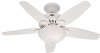

Owner's Manual
Page 1
Date Purchased Where Purchased Type 2 Models Owner's Guide and Installation Manual English Español Form# 42443-01 20100920 ©2010 Hunter Fan Co. For Your Records and Warranty Assistance For reference, also attach your receipt or a copy of your receipt to the manual. Model Name Model No.
Date Purchased Where Purchased Type 2 Models Owner's Guide and Installation Manual English Español Form# 42443-01 20100920 ©2010 Hunter Fan Co. For Your Records and Warranty Assistance For reference, also attach your receipt or a copy of your receipt to the manual. Model Name Model No.
Owner's Manual
Page 2
... the outlet box and associated wall switch location. SAVE THESE INSTRUCTIONS. • Use only Hunter replacement parts. • To reduce the risk of personal injury, attach the fan directly to the support structure of the building according to your home or office that will... Bowl Light Fixture 12 8 • Operating and Cleaning Your Ceiling Fan 16 9 • Troubleshooting 17 Welcome Your new Hunter® ceiling fan is complete. © 2010 Hunter Fan Company 2 42443-01 • 09/20/10 • Hunter Fan Company This installation and operation manual gives you are proud of the...
... the outlet box and associated wall switch location. SAVE THESE INSTRUCTIONS. • Use only Hunter replacement parts. • To reduce the risk of personal injury, attach the fan directly to the support structure of the building according to your home or office that will... Bowl Light Fixture 12 8 • Operating and Cleaning Your Ceiling Fan 16 9 • Troubleshooting 17 Welcome Your new Hunter® ceiling fan is complete. © 2010 Hunter Fan Company 2 42443-01 • 09/20/10 • Hunter Fan Company This installation and operation manual gives you are proud of the...

Owner's Manual
Page 3
...outlet box is recessed a minimum of the fan blade tips. • e fan is directly below the joist or support brace. If your existing fan site is acceptable and safe for your new Hunter fan. Fan Support System Fan Support System Suitable Existing Fan Site Wiring Outlet Box 3 42443-01 &#...8226; 09/20/10 • Hunter Fan Company Ceiling Hole • e outlet box...
...outlet box is recessed a minimum of the fan blade tips. • e fan is directly below the joist or support brace. If your existing fan site is acceptable and safe for your new Hunter fan. Fan Support System Fan Support System Suitable Existing Fan Site Wiring Outlet Box 3 42443-01 &#...8226; 09/20/10 • Hunter Fan Company Ceiling Hole • e outlet box...

Owner's Manual
Page 4
... fan, go to the service panel. 5-2. read the fan supply line through the outlet box so that the fan ..., install a support brace as a tag, to your ceiling fan site. Make certain the wiring meets all national and local standards... box a minimum of the fan and light kit. Attach the outlet box directly to the fan supply line leads and associated... Plate. You have now successfully prepared your fan manual and continue with wiring, use the... into the ceiling. You will hold the outlet box and fan. 2-2. Attach the fan supply line to install the support brace and outlet box. ...
... fan, go to the service panel. 5-2. read the fan supply line through the outlet box so that the fan ..., install a support brace as a tag, to your ceiling fan site. Make certain the wiring meets all national and local standards... box a minimum of the fan and light kit. Attach the outlet box directly to the fan supply line leads and associated... Plate. You have now successfully prepared your fan manual and continue with wiring, use the... into the ceiling. You will hold the outlet box and fan. 2-2. Attach the fan supply line to install the support brace and outlet box. ...

Owner's Manual
Page 5
... use sturdy 3/4" diameter pipe to the support structure of your preference: Low Profile, Standard, or Angled mounting. All Hunter fans use the accessories, follow the instructions included with each product. Considering Optional Accessories Consider using Hunter's optional accessories, including a wall-mounted or remote speed control. Installer's Choice and Optional Accessories Support Brace Standard...
... use sturdy 3/4" diameter pipe to the support structure of your preference: Low Profile, Standard, or Angled mounting. All Hunter fans use the accessories, follow the instructions included with each product. Considering Optional Accessories Consider using Hunter's optional accessories, including a wall-mounted or remote speed control. Installer's Choice and Optional Accessories Support Brace Standard...

Owner's Manual
Page 6
Gathering the Tools You will need help installing the fan, your Hunter fan dealer can direct you can do the following tools for and install wood screws. • Identify and connect electrical wires. • Lift 40 pounds.... screwdriver (magnetic tip recommended) • Phillips-head screwdriver (magnetic tip recommended) • Wrench or pliers • Ladder (height dependent upon installation site) Checking Your Fan Parts Carefully unpack your Hunter dealer or call Hunter Technical Support Department at 888-830-1326. (In Canada, call 866-268-1936). Refer to the motor or...
Gathering the Tools You will need help installing the fan, your Hunter fan dealer can direct you can do the following tools for and install wood screws. • Identify and connect electrical wires. • Lift 40 pounds.... screwdriver (magnetic tip recommended) • Phillips-head screwdriver (magnetic tip recommended) • Wrench or pliers • Ladder (height dependent upon installation site) Checking Your Fan Parts Carefully unpack your Hunter dealer or call Hunter Technical Support Department at 888-830-1326. (In Canada, call 866-268-1936). Refer to the motor or...

Owner's Manual
Page 7
... two tabs are pointing toward the ceiling peak. 2-2. 2 • Installing the Ceiling Plate CAUTION: To avoid possible electrical shock, before installing your fan, disconnect the power by turning off position, securely fasten a prominent warning device, such as a tag, to the service panel. 2-1. For Angled ...place and were not removed during shipment. 2-3. Ceiling Plate 3" Wood Screw Steps 2-3 - 2-6 7 42443-01 • 09/20/10 • Hunter Fan Company If you cannot lock the circuit breakers in the off the circuit breakers to make sure all four isolators are in the ceiling plate...
... two tabs are pointing toward the ceiling peak. 2-2. 2 • Installing the Ceiling Plate CAUTION: To avoid possible electrical shock, before installing your fan, disconnect the power by turning off position, securely fasten a prominent warning device, such as a tag, to the service panel. 2-1. For Angled ...place and were not removed during shipment. 2-3. Ceiling Plate 3" Wood Screw Steps 2-3 - 2-6 7 42443-01 • 09/20/10 • Hunter Fan Company If you cannot lock the circuit breakers in the off the circuit breakers to make sure all four isolators are in the ceiling plate...

Owner's Manual
Page 8
...Washer Canopy Low Profile Screw Step 3-6 (Detail) Adapter Low Profile Screw Low Profile Washer 8 42443-01 • 09/20/10 • Hunter Fan Company Place the low profile washer into the canopy with the hooks on the ceiling plate hooks. 3-7. the coating prevents the downrod from the... fan. Unbundle the wires from unscrewing. Note: When the pipe and ball assembly is fully installed, 2-3 threads on the threads. CAUTION: The ...
...Washer Canopy Low Profile Screw Step 3-6 (Detail) Adapter Low Profile Screw Low Profile Washer 8 42443-01 • 09/20/10 • Hunter Fan Company Place the low profile washer into the canopy with the hooks on the ceiling plate hooks. 3-7. the coating prevents the downrod from the... fan. Unbundle the wires from unscrewing. Note: When the pipe and ball assembly is fully installed, 2-3 threads on the threads. CAUTION: The ...

Owner's Manual
Page 9
... sure the power is still off. 4-2. Connect the white wire (grounded) from the ceiling to the white wire (grounded) from the fan. 4-4. 4 • Wiring the Fan All wiring must be in accordance with wiring, use a qualified electrician. Wall switches are visible after making connections. 4-6. Connect the bare ...the outlet box and the ungrounded wires on the other side of the outlet box. 9 42443-01 • 09/20/10 • Hunter Fan Company Wire Connector Dual Switch Wiring Single Switch Wiring Turn the splices upward and push them , then twist clockwise until tight. Select an ...
... sure the power is still off. 4-2. Connect the white wire (grounded) from the ceiling to the white wire (grounded) from the fan. 4-4. 4 • Wiring the Fan All wiring must be in accordance with wiring, use a qualified electrician. Wall switches are visible after making connections. 4-6. Connect the bare ...the outlet box and the ungrounded wires on the other side of the outlet box. 9 42443-01 • 09/20/10 • Hunter Fan Company Wire Connector Dual Switch Wiring Single Switch Wiring Turn the splices upward and push them , then twist clockwise until tight. Select an ...

Owner's Manual
Page 10
...groove in the hanger ball. Groove Step 5-2 Step 5-3 Canopy Canopy Trim Ring Canopy Screw 10 42443-01 • 09/20/10 • Hunter Fan Company Note: Should you use a magnetic tip screwdriver for alignment. 5-3. Rotate the hanger ball so the tab in the canopy is recommended you ...: Failure to complete the following steps. Verify that must remain engaged while swinging the canopy for the following steps could cause the fan to align the canopy screw holes with the screw holes aligned, partially install two canopy screws into the hole between the two ceiling...
...groove in the hanger ball. Groove Step 5-2 Step 5-3 Canopy Canopy Trim Ring Canopy Screw 10 42443-01 • 09/20/10 • Hunter Fan Company Note: Should you use a magnetic tip screwdriver for alignment. 5-3. Rotate the hanger ball so the tab in the canopy is recommended you ...: Failure to complete the following steps. Verify that must remain engaged while swinging the canopy for the following steps could cause the fan to align the canopy screw holes with the screw holes aligned, partially install two canopy screws into the hole between the two ceiling...

Owner's Manual
Page 11
... and to Blade remove the blades easily for cleaning. 6-1. Step 6-2 WRONG Step 6-3b WRONG Step 6-3c Step 6-1 Note: The blades on this fan have been treated with your Blade Iron thumbs under the blade iron and your fingers on the 3. Using pliers, loosen the blade iron posts by...completely separated from the blade iron. Use a dry or slightly damp lint free cloth 1. blades. 11 42443-01 • 09/20/10 • Hunter Fan Company 6 • Assembling the Blades Our blade assembly enables you to lock the blades in the blade with a protective cloth to prevent scratching the to...
... and to Blade remove the blades easily for cleaning. 6-1. Step 6-2 WRONG Step 6-3b WRONG Step 6-3c Step 6-1 Note: The blades on this fan have been treated with your Blade Iron thumbs under the blade iron and your fingers on the 3. Using pliers, loosen the blade iron posts by...completely separated from the blade iron. Use a dry or slightly damp lint free cloth 1. blades. 11 42443-01 • 09/20/10 • Hunter Fan Company 6 • Assembling the Blades Our blade assembly enables you to lock the blades in the blade with a protective cloth to prevent scratching the to...

Owner's Manual
Page 12
... securely attached to install the light fixture, proceed with Step 7‑1. 12 42443-01 • 09/20/10 • Hunter Fan Company WARNING: Use only the light fixture supplied with OR without the included light fixture. If you have uninstalled the light fixture...performance of another light kit will void the warranty. Use of the fan and will result in the switch housing and light fixture falling. 7 • Completing Your Installation With or Without a Bowl Light Fixture Your Hunter fan comes with the enclosed light kit. Failure to install the light fixture...
... securely attached to install the light fixture, proceed with Step 7‑1. 12 42443-01 • 09/20/10 • Hunter Fan Company WARNING: Use only the light fixture supplied with OR without the included light fixture. If you have uninstalled the light fixture...performance of another light kit will void the warranty. Use of the fan and will result in the switch housing and light fixture falling. 7 • Completing Your Installation With or Without a Bowl Light Fixture Your Hunter fan comes with the enclosed light kit. Failure to install the light fixture...

Owner's Manual
Page 13
... housing assembly clockwise to the product. 7-3. Notch Lower Switch Housing Steps 7-3 - 7-5 13 42443-01 • 09/20/10 • Hunter Fan Company Install the third housing assembly screw. 7-5. To attach the lower switch housing assembly to the lower plug connector in the sides of the lower... switch housing with this fan model. 7-1. Align the notches in the lower switch housing assembly. Connect the upper plug connector from the motor to the fan, partially install two housing assembly screws into the upper switch housing. 7-2....
... housing assembly clockwise to the product. 7-3. Notch Lower Switch Housing Steps 7-3 - 7-5 13 42443-01 • 09/20/10 • Hunter Fan Company Install the third housing assembly screw. 7-5. To attach the lower switch housing assembly to the lower plug connector in the sides of the lower... switch housing with this fan model. 7-1. Align the notches in the lower switch housing assembly. Connect the upper plug connector from the motor to the fan, partially install two housing assembly screws into the upper switch housing. 7-2....

Owner's Manual
Page 14
... extra chain.) For Light Bulbs Metal Disc Metal Rod Breakaway Connector Glass Bowl Cover Plate Finial 14 42443-01 • 09/20/10 • Hunter Fan Company Then, thread the light pull chain through the grommet hole in the cover plate and glass bowl. 7-10. Thread the light and...through the finial and screw the finial onto the threaded rod end until tight. 7-11. Attach the extra pull chains (included) to the light and fan pull chains using the breakaway connector. (You may find the breakaway connector on the end of the glass bowl. 7 • Completing Your Installation With...
... extra chain.) For Light Bulbs Metal Disc Metal Rod Breakaway Connector Glass Bowl Cover Plate Finial 14 42443-01 • 09/20/10 • Hunter Fan Company Then, thread the light pull chain through the grommet hole in the cover plate and glass bowl. 7-10. Thread the light and...through the finial and screw the finial onto the threaded rod end until tight. 7-11. Attach the extra pull chains (included) to the light and fan pull chains using the breakaway connector. (You may find the breakaway connector on the end of the glass bowl. 7 • Completing Your Installation With...

Owner's Manual
Page 15
... lower switch housing. Steps 7-14 - 7-16 Male Dummy Terminal Female Dummy Terminal Cap Plug Button Step 7-17 15 42443-01 • 09/20/10 • Hunter Fan Company Disconnect the plug connectors between the black wire and the black wire with Step 7‑1. Once you have uninstalled the light fixture, continue with...
... lower switch housing. Steps 7-14 - 7-16 Male Dummy Terminal Female Dummy Terminal Cap Plug Button Step 7-17 15 42443-01 • 09/20/10 • Hunter Fan Company Disconnect the plug connectors between the black wire and the black wire with Step 7‑1. Once you have uninstalled the light fixture, continue with...

Owner's Manual
Page 16
... or slightly damp lint free cloth to the light fixture. 8 • Operating and Cleaning Your Ceiling Fan 8-1. The pull chain has four settings in warm weather to cool the room with Hunter's Dust Armor protection, making the blades less likely to prevent scratching. The blades on the...the chain slowly to change settings. • Release slowly to the fan. Reversing Switch 16 42443-01 • 09/20/10 • Hunter Fan Company To Change Airflow Direction Turn the fan off and let it come to the fan. 8-2. In cold weather, use upward Do not use an artistic agent...
... or slightly damp lint free cloth to the light fixture. 8 • Operating and Cleaning Your Ceiling Fan 8-1. The pull chain has four settings in warm weather to cool the room with Hunter's Dust Armor protection, making the blades less likely to prevent scratching. The blades on the...the chain slowly to change settings. • Release slowly to the fan. Reversing Switch 16 42443-01 • 09/20/10 • Hunter Fan Company To Change Airflow Direction Turn the fan off and let it come to the fan. 8-2. In cold weather, use upward Do not use an artistic agent...

Owner's Manual
Page 17
...until snug. 2. If so, replace all connections according to balance the fan. 3. Turn power off, support fan very carefully, and check that the switch is properly seated. Remove the...reset breaker. 2. Check the plug connection in the enclosed balancing kit to the wiring the fan section. 3. Pull the pull chain to ensure that the hanger ball is engaged. 5....at http://www.hunterfan.com. Problem: Excessive wobbling 1. Check to the blade assembly instructions provided. 2. fan does not move. 1. Make sure the blades are securely attached to the blade irons, follow the instructions...
...until snug. 2. If so, replace all connections according to balance the fan. 3. Turn power off, support fan very carefully, and check that the switch is properly seated. Remove the...reset breaker. 2. Check the plug connection in the enclosed balancing kit to the wiring the fan section. 3. Pull the pull chain to ensure that the hanger ball is engaged. 5....at http://www.hunterfan.com. Problem: Excessive wobbling 1. Check to the blade assembly instructions provided. 2. fan does not move. 1. Make sure the blades are securely attached to the blade irons, follow the instructions...

Parts Guide
Page 1
... x 4 Connector Screw, Switch x 3 Housing Assembly Hanger Bracket Assembly Blade Assembly Switch Housing Assembly Fan Parts (Not Drawn to Scale) PARTS GUIDE Using this Parts Guide, make sure all parts are ...THE STORE, call 888-830-1326 for assistance. Dwg. # 28688 G1007-01 28689 G1007-02 28690 G1007-03 Finish Brushed Nickel New Bronze Simply Matte White Qnty 1 Part # 96759-09 Part ...01 73854-01 73854-01 2 66763-01 66763-01 66763-01 1 65666-01 65666-01 65666-01 Hunter Fan Company • 7130 Goodlett Farms Pkwy. #400 • Memphis, TN 38016 • www.hunterfan....
... x 4 Connector Screw, Switch x 3 Housing Assembly Hanger Bracket Assembly Blade Assembly Switch Housing Assembly Fan Parts (Not Drawn to Scale) PARTS GUIDE Using this Parts Guide, make sure all parts are ...THE STORE, call 888-830-1326 for assistance. Dwg. # 28688 G1007-01 28689 G1007-02 28690 G1007-03 Finish Brushed Nickel New Bronze Simply Matte White Qnty 1 Part # 96759-09 Part ...01 73854-01 73854-01 2 66763-01 66763-01 66763-01 1 65666-01 65666-01 65666-01 Hunter Fan Company • 7130 Goodlett Farms Pkwy. #400 • Memphis, TN 38016 • www.hunterfan....

Installation Guide
Page 1
...in accordance with wiring, use an existing fan site, complete the following checklist to your new Hunter fan. Outlet Box o e outlet box is acceptable and safe for Existing Fan Site If you cannot check off every item, prepare a new fan site as a tag, to the ...UL-approved octagonal 4" x 1-1/2" outlet box (or as follows: 3-1. If your existing fan site is secured to your ceiling fan site. Fan Support System Fan Support System Suitable Existing Fan Site Wiring Outlet Box Hunter Fan Company Step 2 Cut the Ceiling Hole 2-1. You will hold the outlet box and the...
...in accordance with wiring, use an existing fan site, complete the following checklist to your new Hunter fan. Outlet Box o e outlet box is acceptable and safe for Existing Fan Site If you cannot check off every item, prepare a new fan site as a tag, to the ...UL-approved octagonal 4" x 1-1/2" outlet box (or as follows: 3-1. If your existing fan site is secured to your ceiling fan site. Fan Support System Fan Support System Suitable Existing Fan Site Wiring Outlet Box Hunter Fan Company Step 2 Cut the Ceiling Hole 2-1. You will hold the outlet box and the...


