
Owners Manual
Page 1
Operators manual Please read these instructions carefully and make sure you understand them before using the machine. Models: AR19/968982102 AR19B/968999277 AR19B/968999358 AR19H/968999363 AR25H/968981104 AR25/968982105 MANUAL NO. 540200239 REV. 02 (11/30/05)
Operators manual Please read these instructions carefully and make sure you understand them before using the machine. Models: AR19/968982102 AR19B/968999277 AR19B/968999358 AR19H/968999363 AR25H/968981104 AR25/968982105 MANUAL NO. 540200239 REV. 02 (11/30/05)

Owners Manual
Page 2
... You Start...10 Aerating ...10 Throttle Adjustment (Model AR25 Honda engine only 11 Rear Wheel Adjustment ...12 Turning and Maneuvering...12 Operating on Hills ...12 Section 3 · Maintenance and Service Instructions Page Transporting the Husqvarna Aerator 13 Cleaning and Washing ...13 Two-Minute Warning ...13 Storage ...13 Preventative Maintenance Schedule Inspection Schedule ...14 Lubrication Schedule ...14 Tine Wear ...14 Service Engine Service & Maintenance 14 Drive Train Engine Removal and Replacement 15 Drive Belt Replacement and Adjustment 15 Clutch Cable Removal and...
... You Start...10 Aerating ...10 Throttle Adjustment (Model AR25 Honda engine only 11 Rear Wheel Adjustment ...12 Turning and Maneuvering...12 Operating on Hills ...12 Section 3 · Maintenance and Service Instructions Page Transporting the Husqvarna Aerator 13 Cleaning and Washing ...13 Two-Minute Warning ...13 Storage ...13 Preventative Maintenance Schedule Inspection Schedule ...14 Lubrication Schedule ...14 Tine Wear ...14 Service Engine Service & Maintenance 14 Drive Train Engine Removal and Replacement 15 Drive Belt Replacement and Adjustment 15 Clutch Cable Removal and...

Owners Manual
Page 3
...) w/o wls. 41" x 34" x 30" (104 x 86 x 76cm) Operator's Guide SPECIFICATIONS A) POWER UNIT Engine Clutch Primary drive Secondary drive Gear reduction AR19 3.5HP Briggs I/C (2.6kw) 4HP Honda (3kw) Belt tensioner One V-belt (A-44") Permalube Chain 6:1 AR25 3.5HP Briggs l/C (2.6kw) 4HP Honda (3kw) Belt tensioner One V-belt (A-44") Permalube Chain 6:1 B) WHEELS Bearings Rear tires Front tire FRONT - ¾" (1.9 cm) sealed ball bearings with stamping kit REAR - ¾" (1.9 cm) roller bearing 8" x 2" (20 x 5cm...
...) w/o wls. 41" x 34" x 30" (104 x 86 x 76cm) Operator's Guide SPECIFICATIONS A) POWER UNIT Engine Clutch Primary drive Secondary drive Gear reduction AR19 3.5HP Briggs I/C (2.6kw) 4HP Honda (3kw) Belt tensioner One V-belt (A-44") Permalube Chain 6:1 AR25 3.5HP Briggs l/C (2.6kw) 4HP Honda (3kw) Belt tensioner One V-belt (A-44") Permalube Chain 6:1 B) WHEELS Bearings Rear tires Front tire FRONT - ¾" (1.9 cm) sealed ball bearings with stamping kit REAR - ¾" (1.9 cm) roller bearing 8" x 2" (20 x 5cm...
Owners Manual
Page 6
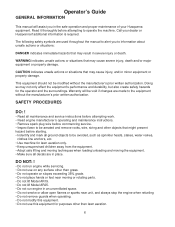
Operator's Guide GENERAL INFORMATION This manual will be void if changes are used throughout the manual to the equipment without the manufacturer's prior written authorization. SAFETY PROCEDURES DO: ! • Read all maintenance and service instructions before attempting work. • Read engine manufacturer's operating and maintenance instructions. • Remove spark plug wire before commencing service. • Inspect lawn to be aerated and remove rocks, wire, string and other than grass. • Do not operate on slopes...
Operator's Guide GENERAL INFORMATION This manual will be void if changes are used throughout the manual to the equipment without the manufacturer's prior written authorization. SAFETY PROCEDURES DO: ! • Read all maintenance and service instructions before attempting work. • Read engine manufacturer's operating and maintenance instructions. • Remove spark plug wire before commencing service. • Inspect lawn to be aerated and remove rocks, wire, string and other than grass. • Do not operate on slopes...

Owners Manual
Page 7
A - Model AR19 & AR25 only (1 ea) B - SAFETY AND INSTRUCTION DECALS The following decals are missing or not legible, replace them before operating aerator. Model AR19 only (1 ea) J - Model AR25 only (1 ea) I - Model AR19 & AR25 only (2 ea) C - Model AR19 & AR25 only (1 ea) F - Model AR19 & AR25 only (1 ea) G - Model AR25 only (2 ea) D1 - Model AR19 & AR25 only (1 ea) If any are found on Model AR19 and AR25 aerators. Model AR19 & AR25 only (1 ea) 7 K - Model AR19 & AR25 only (1 ea) H - Model AR19 only (1 ea) D2 - Model AR25 only (1 ea) E -
A - Model AR19 & AR25 only (1 ea) B - SAFETY AND INSTRUCTION DECALS The following decals are missing or not legible, replace them before operating aerator. Model AR19 only (1 ea) J - Model AR25 only (1 ea) I - Model AR19 & AR25 only (2 ea) C - Model AR19 & AR25 only (1 ea) F - Model AR19 & AR25 only (1 ea) G - Model AR25 only (2 ea) D1 - Model AR19 & AR25 only (1 ea) If any are found on Model AR19 and AR25 aerators. Model AR19 & AR25 only (1 ea) 7 K - Model AR19 & AR25 only (1 ea) H - Model AR19 only (1 ea) D2 - Model AR25 only (1 ea) E -
Owners Manual
Page 8
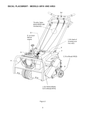
MODELS AR19 AND AR25 D2 Throttle Cable Model AR25 with Honda Only D1 E (on deck behind engine G H I (On back of housing over tine rotor) K F C (For Model AR25) B J (For Model AR25) A (For Model AR19) Figure 3 8 DECAL PLACEMENT -
MODELS AR19 AND AR25 D2 Throttle Cable Model AR25 with Honda Only D1 E (on deck behind engine G H I (On back of housing over tine rotor) K F C (For Model AR25) B J (For Model AR25) A (For Model AR19) Figure 3 8 DECAL PLACEMENT -

Owners Manual
Page 9
... of lever on handle mounting brackets (see parts manual. 5. Attach end of cable to the "S" hook located on assembly, see Figure 4). 7. For further detail on the belt idler pulley. 8. (Honda Engines Only) Connect the throttle cable by attaching the throttle spring to OUTER side of control rod to the throttle/ clutch control lever. (see Figure 5-C). 6. NOTE: Watch for nails and wood splinters. 2. Operator's Guide ASSEMBLY INSTRUCTIONS Model AR19 1. Wear eye protection. Remove wooden blocks. Lawn Aerator is shipped with handle folded. Model...
... of lever on handle mounting brackets (see parts manual. 5. Attach end of cable to the "S" hook located on assembly, see Figure 4). 7. For further detail on the belt idler pulley. 8. (Honda Engines Only) Connect the throttle cable by attaching the throttle spring to OUTER side of control rod to the throttle/ clutch control lever. (see Figure 5-C). 6. NOTE: Watch for nails and wood splinters. 2. Operator's Guide ASSEMBLY INSTRUCTIONS Model AR19 1. Wear eye protection. Remove wooden blocks. Lawn Aerator is shipped with handle folded. Model...
Owners Manual
Page 10
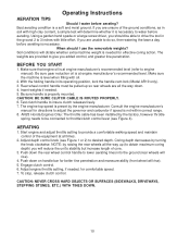
... ground conditions, as in its operating position, lock the handle cam lock (Model AR19 only). 3. Make sure that engine oil is preset by turning the knob clockwise. AERATING 1. Start engine and adjust throttle setting to give you are provided to provide a comfortable walking speed and maintain control of the equipment at all the way up so rear wheels are unsure of core. 3. Operating Instructions AERATION TIPS Should I use the removalole weights? Best...
... ground conditions, as in its operating position, lock the handle cam lock (Model AR19 only). 3. Make sure that engine oil is preset by turning the knob clockwise. AERATING 1. Start engine and adjust throttle setting to give you are provided to provide a comfortable walking speed and maintain control of the equipment at all the way up so rear wheels are unsure of core. 3. Operating Instructions AERATION TIPS Should I use the removalole weights? Best...
Owners Manual
Page 11
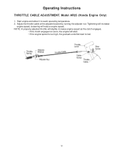
Adjust the throttle cable at the adjuster bracket by turning the adjuster nut. Tightening will increase engine speed, loosening will stall. • If the engine speed is too high, the gradual controlled start is lost. 11 Start engine and allow it to reach operating temperature. 2. NOTE: A properly adjusted throttle will slightly increase engine speed as the clutch engages. • If the clutch engages too soon, the engine will reduce engine speed. Model AR25 (Honda Engine Only) 1. Operating Instructions THROTTLE CABLE ADJUSTMENT.
Adjust the throttle cable at the adjuster bracket by turning the adjuster nut. Tightening will increase engine speed, loosening will stall. • If the engine speed is too high, the gradual controlled start is lost. 11 Start engine and allow it to reach operating temperature. 2. NOTE: A properly adjusted throttle will slightly increase engine speed as the clutch engages. • If the clutch engages too soon, the engine will reduce engine speed. Model AR25 (Honda Engine Only) 1. Operating Instructions THROTTLE CABLE ADJUSTMENT.
Owners Manual
Page 12
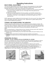
... walking speed. When reversing direction or making sharp turns two methods of the cores pulled can be used on steep slopes. Operating Instructions REAR WHEEL ADJUSTMENT The rear wheel depth/stability control knob (see below "Operating on Hills." Adjusting for the conditions you face: (A) Release clutch control handle, pull up rear wheel control handle, then pivot machine on rear wheels to the full up position, you can control the penetration of an inch. This...
... walking speed. When reversing direction or making sharp turns two methods of the cores pulled can be used on steep slopes. Operating Instructions REAR WHEEL ADJUSTMENT The rear wheel depth/stability control knob (see below "Operating on Hills." Adjusting for the conditions you face: (A) Release clutch control handle, pull up rear wheel control handle, then pivot machine on rear wheels to the full up position, you can control the penetration of an inch. This...
Owners Manual
Page 13
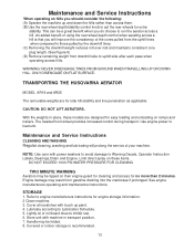
... ON FLAT SURFACE. TRANSPORTING THE HUSQVARNA AERATOR MODEL AR19 and AR25 The removable weights are designed for extra stability. Maintenance and Service Instructions CLEANING AND WASHING Regular cleaning, washing and lubricating will improve the consistency of the cores pulled from the uphill tines when compared to run the aerator across hills. See engine manufacturers operating and maintenance instructions. Maintenance and Service Instructions When operating on hills you should consider...
... ON FLAT SURFACE. TRANSPORTING THE HUSQVARNA AERATOR MODEL AR19 and AR25 The removable weights are designed for extra stability. Maintenance and Service Instructions CLEANING AND WASHING Regular cleaning, washing and lubricating will improve the consistency of the cores pulled from the uphill tines when compared to run the aerator across hills. See engine manufacturers operating and maintenance instructions. Maintenance and Service Instructions When operating on hills you should consider...
Owners Manual
Page 14
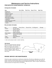
... • Engine Oil • Gear box oil • Engine air cleaner • Clutch & cable • Chain tension • Belt wear & tension • Tine wear & condition • Fasteners • Sprockets & set screws • Frame condition • Decals B) Lubrication Schedule Out of Box First 5 hrs. Inspect tines using the drawing, replace when at minimum length or before. (Tines are 5" when new.) ENGINE SERVICE AND MAINTENANCE Follow the engine manufacturers maintenance instructions. DO NOT...
... • Engine Oil • Gear box oil • Engine air cleaner • Clutch & cable • Chain tension • Belt wear & tension • Tine wear & condition • Fasteners • Sprockets & set screws • Frame condition • Decals B) Lubrication Schedule Out of Box First 5 hrs. Inspect tines using the drawing, replace when at minimum length or before. (Tines are 5" when new.) ENGINE SERVICE AND MAINTENANCE Follow the engine manufacturers maintenance instructions. DO NOT...
Owners Manual
Page 15
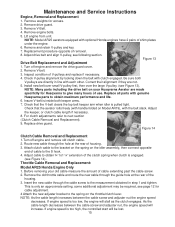
... adjuster nut, the engine speed will be required, see Figure 14). Check that the V-belt clears the top belt keeper arm when idler is too high, the controlled start will increase. Remove weights for cable adjustment. 4 Attach the new adjuster bracket to the bracket on the spring on your old cable measure the amount of housing. 3. Remove V-Belt. 4. Install new belt over small V-pulley first, then over the large V-pulley. (see following section. Replace all parts with clutch engaged. Replace drive guard. Attach clutch cable...
... adjuster nut, the engine speed will be required, see Figure 14). Check that the V-belt clears the top belt keeper arm when idler is too high, the controlled start will increase. Remove weights for cable adjustment. 4 Attach the new adjuster bracket to the bracket on the spring on your old cable measure the amount of housing. 3. Remove V-Belt. 4. Install new belt over small V-pulley first, then over the large V-pulley. (see following section. Replace all parts with clutch engaged. Replace drive guard. Attach clutch cable...
Owners Manual
Page 16
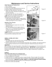
...adjustment bolt and lock nut 4. Tighten lock nut. The handle cam lock must be replaced to avoid unwanted loosening of sprockets when replacing drive chain. WARNING: SECURE HANDLE TO PREVENT AERATOR FROM TIPPING. 5. Install new chain from the fuel tank. 2. Remove the wheel shaft bearing bolts (4 on the AR19 and 6 on outboard side. Turn off the ground. Adjusting Chain Tension 1. WHEELS Drive Wheel Shaft Removal and Replacement 1. Inspect and align sprockets. (see Figures 15 and 17). 4. Maintenance and Service Instructions Chain Removal and Replacement...
...adjustment bolt and lock nut 4. Tighten lock nut. The handle cam lock must be replaced to avoid unwanted loosening of sprockets when replacing drive chain. WARNING: SECURE HANDLE TO PREVENT AERATOR FROM TIPPING. 5. Install new chain from the fuel tank. 2. Remove the wheel shaft bearing bolts (4 on the AR19 and 6 on outboard side. Turn off the ground. Adjusting Chain Tension 1. WHEELS Drive Wheel Shaft Removal and Replacement 1. Inspect and align sprockets. (see Figures 15 and 17). 4. Maintenance and Service Instructions Chain Removal and Replacement...
Owners Manual
Page 17
... aerator rest on level ground and engine is shut off . 2. NOTE: Sprocket is on the tines. 3. Model AR19: hub side away from shaft. Model AR25 has 3 bearings. Align and tighten the sprocket (there are rusted in section "Chain Removal and Replacement.(see Figure 18) 6. Make sure unit is double set screwed. Lower the rear wheel control handle to prevent loss. Install a new wheel with grease fitting facing out...
... aerator rest on level ground and engine is shut off . 2. NOTE: Sprocket is on the tines. 3. Model AR19: hub side away from shaft. Model AR25 has 3 bearings. Align and tighten the sprocket (there are rusted in section "Chain Removal and Replacement.(see Figure 18) 6. Make sure unit is double set screwed. Lower the rear wheel control handle to prevent loss. Install a new wheel with grease fitting facing out...
Owners Manual
Page 18
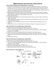
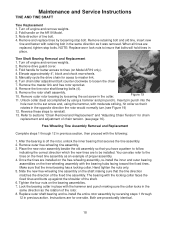
... loosening the set screw and, using a hammer and pin punch). Remove outer free-wheeling tine assembly. 3. When all tines are to the tines on the bearing assemblies. 7. Reverse these steps to insure that you have a pattern to tines (on the AR19 Model. 3. You can also refer to be installed. Remove the rotor shaft assembly. 10. Hand tighten the nuts only. 5. Replace outer shaft bearing and re-install the entire...
... loosening the set screw and, using a hammer and pin punch). Remove outer free-wheeling tine assembly. 3. When all tines are to the tines on the bearing assemblies. 7. Reverse these steps to insure that you have a pattern to tines (on the AR19 Model. 3. You can also refer to be installed. Remove the rotor shaft assembly. 10. Hand tighten the nuts only. 5. Replace outer shaft bearing and re-install the entire...


