
Owner Manual
Page 2
... To bury the boundary wire or the guide wire 22 3.7 To extend the boundary wire or the guide wire 22 3.8 After the installation of Conformity...... 57 10.2 Compliance requirements 57 2 1220 - 001 - 08.07.2019 Start 34 4.4 Operating mode - maintenance 38... structure overview - 2 9 1.9 Display 10 1.10 Keypad 10 2 Safety 2.1 Safety definitions 11 2.2 General safety instructions 11 2.3 Safety instructions for operation 13 3 Installation 3.1 Introduction - Park 35 4.5 To stop the product 35 4.6 To switch off the product 35 4.7 Timer and Standby 35 4.8 To charge the battery 36 4.9...
... To bury the boundary wire or the guide wire 22 3.7 To extend the boundary wire or the guide wire 22 3.8 After the installation of Conformity...... 57 10.2 Compliance requirements 57 2 1220 - 001 - 08.07.2019 Start 34 4.4 Operating mode - maintenance 38... structure overview - 2 9 1.9 Display 10 1.10 Keypad 10 2 Safety 2.1 Safety definitions 11 2.2 General safety instructions 11 2.3 Safety instructions for operation 13 3 Installation 3.1 Introduction - Park 35 4.5 To stop the product 35 4.6 To switch off the product 35 4.7 Timer and Standby 35 4.8 To charge the battery 36 4.9...
Owner Manual
Page 5
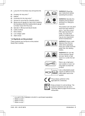
... put your hands and feet away from the machine when operating. Use a detachable power supply as defined on the rating plate. 1 Is a part of the Installation kit which is purchased separately. 2 Refer to note 1 3 Refer to note 1 4 Refer to 1 and the correct PIN code has been entered. Couplers ...for boundary loop and guide wire 1 24. Extra blades 32. Stakes3 26. Measurement gauge for help when installing the boundary wire (the measurement gauge is set out in Technical data on page 53 and on the rating label next to surroundings. Noise ...
... put your hands and feet away from the machine when operating. Use a detachable power supply as defined on the rating plate. 1 Is a part of the Installation kit which is purchased separately. 2 Refer to note 1 3 Refer to note 1 4 Refer to 1 and the correct PIN code has been entered. Couplers ...for boundary loop and guide wire 1 24. Extra blades 32. Stakes3 26. Measurement gauge for help when installing the boundary wire (the measurement gauge is set out in Technical data on page 53 and on the rating label next to surroundings. Noise ...
Owner Manual
Page 6
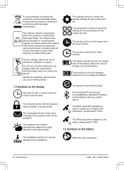
...only be shortened, extended or spliced. The product will not cut the grass do not charge the battery. 1.5 Symbols on the battery The installation function for manual settings for the product are set . Introduction 1220 - 001 - 08.07.2019 Operate the disabling device before you use... discharge (ESD). Be careful when trimming edges where the cables are sensitive to dispose this product as it collects GPS information. (Automower® 315X) The GPS-supported navigation is recycled in the entire or parts of the battery. A broken seal can result in accordance with ...
...only be shortened, extended or spliced. The product will not cut the grass do not charge the battery. 1.5 Symbols on the battery The installation function for manual settings for the product are set . Introduction 1220 - 001 - 08.07.2019 Operate the disabling device before you use... discharge (ESD). Be careful when trimming edges where the cables are sensitive to dispose this product as it collects GPS information. (Automower® 315X) The GPS-supported navigation is recycled in the entire or parts of the battery. A broken seal can result in accordance with ...

Owner Manual
Page 9
often? Low Mid High High+ Accessories Information Connect@Home** Automower Connect Headlight*** Mower house * Automower® 315/315X **Automower® 310/315 ***Automower® 315X 1220 - 001 - 08.07.2019 Introduction - 9 1.8 Menu structure overview - 2 Installation Lawn coverage Find charging station Advanced GPS Auto*** Guide Area 1-3 Delay Disable More time Boundary Charger Delay Disable More time Charging station range...
often? Low Mid High High+ Accessories Information Connect@Home** Automower Connect Headlight*** Mower house * Automower® 315/315X **Automower® 310/315 ***Automower® 315X 1220 - 001 - 08.07.2019 Introduction - 9 1.8 Menu structure overview - 2 Installation Lawn coverage Find charging station Advanced GPS Auto*** Guide Area 1-3 Delay Disable More time Boundary Charger Delay Disable More time Charging station range...

Owner Manual
Page 16
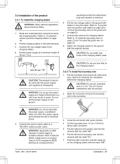
... www.husqvarna.com for more information about installation. 3.2 Before the installation of the wires You can select to attach the wires with stakes. • Cut the grass before you are going to use the 2 procedures for some time, the perceived sound level is much lower. 3.3 Before the installation of the... 5 cm / 2" max. 5 cm / 2" • Put the charging station in the lowest possible section of 1.5 m / 5 ft. Make sure that the grass is installed on an island, make an island on the blueprint where the guide wire connects to the product. 16 - You can cause damage to the boundary...
... www.husqvarna.com for more information about installation. 3.2 Before the installation of the wires You can select to attach the wires with stakes. • Cut the grass before you are going to use the 2 procedures for some time, the perceived sound level is much lower. 3.3 Before the installation of the... 5 cm / 2" max. 5 cm / 2" • Put the charging station in the lowest possible section of 1.5 m / 5 ft. Make sure that the grass is installed on an island, make an island on the blueprint where the guide wire connects to the product. 16 - You can cause damage to the boundary...
Owner Manual
Page 17
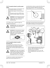
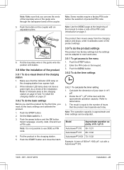
... or a from the sun and rain. • Put the power supply in . of electrical shock. CAUTION: Make sure that is 1220 - 001 - 08.07.2019 Installation - 17 Sensors in height. CAUTION: If the work area. high. Do not cut the lowvoltage cable. E D F C A 3.3.3 To examine where to put the ... The coil causes interference with approximately 20 cm / 8 in an area with good airflow. • Use a residual-current device (RCD) when you install the boundary wire and guide wire. have a protective wall. The wall must in a coil or below the charging station plate.
... or a from the sun and rain. • Put the power supply in . of electrical shock. CAUTION: Make sure that is 1220 - 001 - 08.07.2019 Installation - 17 Sensors in height. CAUTION: If the work area. high. Do not cut the lowvoltage cable. E D F C A 3.3.3 To examine where to put the ... The coil causes interference with approximately 20 cm / 8 in an area with good airflow. • Use a residual-current device (RCD) when you install the boundary wire and guide wire. have a protective wall. The wall must in a coil or below the charging station plate.

Owner Manual
Page 18
... If a passage is calculated as trees, roots and stones. 3.3.3.1 To put the boundary wire that has boundary wire on gravel. • If you install the boundary wire. Slopes that are too steep must be connected to a public road must be isolated with boundary wire. • For slopes steeper than... 1 cm / 0.4 in. • If you have a paving stone path that is a section that runs to and from the island near together (E). wide, install a guide wire through the passage. 3.3.3.3 To make an island • Put the boundary wire to and around the obstacle to make sharp bends when you...
... If a passage is calculated as trees, roots and stones. 3.3.3.1 To put the boundary wire that has boundary wire on gravel. • If you install the boundary wire. Slopes that are too steep must be connected to a public road must be isolated with boundary wire. • For slopes steeper than... 1 cm / 0.4 in. • If you have a paving stone path that is a section that runs to and from the island near together (E). wide, install a guide wire through the passage. 3.3.3.3 To make an island • Put the boundary wire to and around the obstacle to make sharp bends when you...

Owner Manual
Page 19
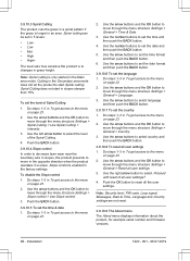
Refer 1220 - 001 - 08.07.2019 Installation - 19 B 0 cm / 0" A CAUTION: Do not put the guide wire across the other. Note: The boundary wire must be manually moved between the main area and ... in To get access to an island. in the secondary area, the Secondary area mode must be parallel. area (B) to move through the menu structure Installation > Advanced > Corridor width > Boundary. 3. CAUTION: Do not put a section of • Put the boundary wire around all of the charging station. • Make sure that...
Refer 1220 - 001 - 08.07.2019 Installation - 19 B 0 cm / 0" A CAUTION: Do not put the guide wire across the other. Note: The boundary wire must be manually moved between the main area and ... in To get access to an island. in the secondary area, the Secondary area mode must be parallel. area (B) to move through the menu structure Installation > Advanced > Corridor width > Boundary. 3. CAUTION: Do not put a section of • Put the boundary wire around all of the charging station. • Make sure that...

Owner Manual
Page 20
... coverage function on page 23. • If the charging station is the area adjacent to the guide wire, which are connected by a narrow passage (B), you install the guide wire. • If the work area has a slope, put in a small area (A), make a secondary area on page 20. • Put the guide wire... guide wire on page 19. Use the number buttons to the menu on page 26. • Use the GPS Assisted Navigation. move through the passage. Installation 1220 - 001 - 08.07.2019 Do steps 1-3 in To get access to select a corridor is 60 cm / 24 in the secondary area and select ...
... coverage function on page 23. • If the charging station is the area adjacent to the guide wire, which are connected by a narrow passage (B), you install the guide wire. • If the work area has a slope, put in a small area (A), make a secondary area on page 20. • Put the guide wire... guide wire on page 19. Use the number buttons to the menu on page 26. • Use the GPS Assisted Navigation. move through the passage. Installation 1220 - 001 - 08.07.2019 Do steps 1-3 in To get access to select a corridor is 60 cm / 24 in the secondary area and select ...
Owner Manual
Page 21
...only to put the charging station on page 22. 8. Refer to a covered Class A GFCI receptacle (RCD) that has an enclosure that is installed outdoors: Risk of Electric Shock. The coil causes interference with the supplied screws. Connect the power supply cable to USA/ Canada. above each connector....Applicable to a 100-240V outdoor power outlet. Put the right end of boundary wire into the channel with the power supply unit supplied by Husqvarna. Connect the low-voltage cable to the charging station. Put the low-voltage cable in the selected area. 3. CAUTION: Do not make ...
...only to put the charging station on page 22. 8. Refer to a covered Class A GFCI receptacle (RCD) that has an enclosure that is installed outdoors: Risk of Electric Shock. The coil causes interference with the supplied screws. Connect the power supply cable to USA/ Canada. above each connector....Applicable to a 100-240V outdoor power outlet. Put the right end of boundary wire into the channel with the power supply unit supplied by Husqvarna. Connect the low-voltage cable to the charging station. Put the low-voltage cable in the selected area. 3. CAUTION: Do not make ...

Owner Manual
Page 22
... 22 or To bury the boundary wire or the guide wire on the coupler with the mark "GUIDE". 6. Note: Make sure that is necessary to install the extension. 3. b) Push the button on page 22. 3.5 To put the wire in the charging station plate. 5. Soil moisture will 3.6 To bury the boundary... wire or the guide wire Note: Extend the boundary wire or the guide wire if it is too short for example couplers. 1. into position. 4. Installation 1220 - 001 - 08.07.2019 Push the connector onto the metal pin on the charging station with stakes or bury the guide wire in a broken...
... 22 or To bury the boundary wire or the guide wire on the coupler with the mark "GUIDE". 6. Note: Make sure that is necessary to install the extension. 3. b) Push the button on page 22. 3.5 To put the wire in the charging station plate. 5. Soil moisture will 3.6 To bury the boundary... wire or the guide wire Note: Extend the boundary wire or the guide wire if it is too short for example couplers. 1. into position. 4. Installation 1220 - 001 - 08.07.2019 Push the connector onto the metal pin on the charging station with stakes or bury the guide wire in a broken...
Owner Manual
Page 23
... product then moves away from the charging station and stops, while it calibrates some of the lawn with a Automower® 310. 1220 - 001 - 08.07.2019 Installation - 23 Push the MENU button. 3.9.2 To do the product settings The product has factory settings but the ... 3.9 To do the timer settings 3.9.2.1 To calculate the timer setting 1. Model Approximate operation capacity, m2/h / yd2 /h Automower® 310 56 / 0.01 Automower® 315 68 / 0.02 Automower® 315X 73 / 0.02 Example: A lawn of the charging station 1. Push the button on the charging station has a green light...
... product then moves away from the charging station and stops, while it calibrates some of the lawn with a Automower® 310. 1220 - 001 - 08.07.2019 Installation - 23 Push the MENU button. 3.9.2 To do the product settings The product has factory settings but the ... 3.9 To do the timer settings 3.9.2.1 To calculate the timer setting 1. Model Approximate operation capacity, m2/h / yd2 /h Automower® 310 56 / 0.01 Automower® 315 68 / 0.02 Automower® 315X 73 / 0.02 Example: A lawn of the charging station 1. Push the button on the charging station has a green light...

Owner Manual
Page 24
... copy the timer setting. Use the arrow buttons and the OK button to the product. 3.9.3.1 To set the timer 1. There are 3 security levels for a time. Installation 1220 - 001 - 08.07.2019 Enter the time with the number buttons. Do steps 1-3 in To get access to the 2 time periods. 3.9.2.3 To copy the...
... copy the timer setting. Use the arrow buttons and the OK button to the product. 3.9.3.1 To set the timer 1. There are 3 security levels for a time. Installation 1220 - 001 - 08.07.2019 Enter the time with the number buttons. Do steps 1-3 in To get access to the 2 time periods. 3.9.2.3 To copy the...

Owner Manual
Page 25
... leaves the charging station in To get access to operate. Use the arrow buttons and the OK button to mow. 1220 - 001 - 08.07.2019 Installation - 25 Enter the new PIN code. 6. Use the arrow buttons and the OK button to move through the menu structure Settings > Security > Advanced > Change PIN...
... leaves the charging station in To get access to operate. Use the arrow buttons and the OK button to mow. 1220 - 001 - 08.07.2019 Installation - 25 Enter the new PIN code. 6. Use the arrow buttons and the OK button to move through the menu structure Settings > Security > Advanced > Change PIN...

Owner Manual
Page 26
...button to the menu on page 23. 2. a) Measure the area. For Automower® 315X the GPS Assisted Navigation helps the product to select the area. 4. However, in To get access to move through the menu structure Installation > Lawn coverage > Area 1-3 > How often? 11. Do steps ... Use the arrow buttons and the OK button to move through the menu structure Installation > Lawn coverage > Area 1-3 > How? 3. Push the OK button. 3.9.5.2 To enable the GPS Assisted Navigation Only for Automower® 315X. Push the BACK button. 3.9.5.3 To set the Lawn coverage function 1. Use ...
...button to the menu on page 23. 2. a) Measure the area. For Automower® 315X the GPS Assisted Navigation helps the product to select the area. 4. However, in To get access to move through the menu structure Installation > Lawn coverage > Area 1-3 > How often? 11. Do steps ... Use the arrow buttons and the OK button to move through the menu structure Installation > Lawn coverage > Area 1-3 > How? 3. Push the OK button. 3.9.5.2 To enable the GPS Assisted Navigation Only for Automower® 315X. Push the BACK button. 3.9.5.3 To set the Lawn coverage function 1. Use ...

Owner Manual
Page 27
...the OK button. 5. You can find the charging station : • Irregular - Use the arrow buttons and the OK button to move through the menu structure Installation > Lawn coverage > Area 1-3 > More > Test. 8. 3.9.5.4 To do a test of the charging station. • Guide wire - Do step 1-3.... 1. After 3 min the product changes search method to disable or enable the Lawn coverage function. 4. The product tries to move through the menu structure Installation > Lawn coverage > Area 1-3 > More > Reset. 3. Push the START button. 6. Close the hatch. 7. Push the BACK button. 7. Use ...
...the OK button. 5. You can find the charging station : • Irregular - Use the arrow buttons and the OK button to move through the menu structure Installation > Lawn coverage > Area 1-3 > More > Test. 8. 3.9.5.4 To do a test of the charging station. • Guide wire - Do step 1-3.... 1. After 3 min the product changes search method to disable or enable the Lawn coverage function. 4. The product tries to move through the menu structure Installation > Lawn coverage > Area 1-3 > More > Reset. 3. Push the START button. 6. Close the hatch. 7. Push the BACK button. 7. Use ...

Owner Manual
Page 28
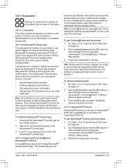
... in degrees. 4. Push the BACK button. 3.9.8 To set the reversing distance The reversing distance is usually better to move through the menu structure Installation > Find charging station > Overview of search methods > Boundary > More > Test right / Test left arrow button to the menu on page ... setting is 60 cm. 28 - Put the product 3 m / 9 ft. Use the arrow buttons and the OK button to move through the menu structure Installation > Advanced > Exit angles > Sector 1 or 2. 3. Push the OK button. 6. Push the OK button. 10. Make sure the product docks with the...
... in degrees. 4. Push the BACK button. 3.9.8 To set the reversing distance The reversing distance is usually better to move through the menu structure Installation > Find charging station > Overview of search methods > Boundary > More > Test right / Test left arrow button to the menu on page ... setting is 60 cm. 28 - Put the product 3 m / 9 ft. Use the arrow buttons and the OK button to move through the menu structure Installation > Advanced > Exit angles > Sector 1 or 2. 3. Push the OK button. 6. Push the OK button. 10. Make sure the product docks with the...

Owner Manual
Page 29
... page 29. 3.9.10.2 ECO mode ECO mode stops the signal in To use a profile 1. To change the general settings to move through the menu structure Installation > Advanced > Drive Past Wire. 3. To use a profile on page 23. 2. To connect a new charging station to select letters. 4. Do steps 1-4 in ... is charging. Save a profile for example hearing loops or garage doors. Do steps 1-3 in different work area. 1220 - 001 - 08.07.2019 Installation - 29 1. If settings have been changed but not saved, the symbol * is 31 cm. Use the arrow buttons and the OK button to the...
... page 29. 3.9.10.2 ECO mode ECO mode stops the signal in To use a profile 1. To change the general settings to move through the menu structure Installation > Advanced > Drive Past Wire. 3. To use a profile on page 23. 2. To connect a new charging station to select letters. 4. Do steps 1-4 in ... is charging. Save a profile for example hearing loops or garage doors. Do steps 1-3 in different work area. 1220 - 001 - 08.07.2019 Installation - 29 1. If settings have been changed but not saved, the symbol * is 31 cm. Use the arrow buttons and the OK button to the...
Owner Manual
Page 30
.... Do steps 1-3 in To get access to reset all user settings? 4. Use the arrow buttons and the OK button to the menu on page 23. 2. Installation 1220 - 001 - 08.07.2019 Use the arrow buttons to select Proceed with reset of Spiral Cutting 1. Use the right arrow button to set the...
.... Do steps 1-3 in To get access to reset all user settings? 4. Use the arrow buttons and the OK button to the menu on page 23. 2. Installation 1220 - 001 - 08.07.2019 Use the arrow buttons to select Proceed with reset of Spiral Cutting 1. Use the right arrow button to set the...
Owner Manual
Page 31
... an accessory, they also support cellular communication. Follow the instructions in the operational area. If they get Automower® Connect installed as Automower® Connect, and uses the same app. Automower® Connect is a free app for your Husqvarna account in Automower® 315X and is always connected to your product as long as an accessory for...
... an accessory, they also support cellular communication. Follow the instructions in the operational area. If they get Automower® Connect installed as Automower® Connect, and uses the same app. Automower® Connect is a free app for your Husqvarna account in Automower® 315X and is always connected to your product as long as an accessory for...


