
Maintenance Manual
Page 3
... 15 Related Publications 17 Model A00 Publications 17 Models 001 and 002 Publications 17 Model 003 Publications 18 Common Publications 18 Preface - What's New in the Model 003 19 Chapter 1. Diagnosing Problems 20 Maintenance Analysis Procedures (MAPs 20 Defining The Problem 20...003 41 Attachment Card Procedure 1 50 Attachment Card Procedure 2 56 MAP 0122: Network Print Server Attachment 59 MAP 0130: No Paper Movement 62 MAP 0131: Paper Path Sensor 66 MAP 0140: Printhead Drive 70 MAP 0150: Power Supply 75 MAP 0160: Ribbon Feed and Ribbon Lift 89 © Copyright IBM...
... 15 Related Publications 17 Model A00 Publications 17 Models 001 and 002 Publications 17 Model 003 Publications 18 Common Publications 18 Preface - What's New in the Model 003 19 Chapter 1. Diagnosing Problems 20 Maintenance Analysis Procedures (MAPs 20 Defining The Problem 20...003 41 Attachment Card Procedure 1 50 Attachment Card Procedure 2 56 MAP 0122: Network Print Server Attachment 59 MAP 0130: No Paper Movement 62 MAP 0131: Paper Path Sensor 66 MAP 0140: Printhead Drive 70 MAP 0150: Power Supply 75 MAP 0160: Ribbon Feed and Ribbon Lift 89 © Copyright IBM...
Maintenance Manual
Page 4
...0210: Intermittent Failures 130 MAPs Reference Tables 133 Reference Table 1, Model A00 Error Messages 133 Reference Table 2, Models 001, 002, and 003 Error Messages 136 Reference Table 3, No Printed Characters 146 Reference Table 4, Print Quality Failures 146 Reference Table 5, Operator Panel and Miscellaneous Problems... Reference Table 8, Power Supply Connector Pins and Voltages 156 Reference Table 9, Base Code Compatibilities 157 Reference Table 10, Ribbon Lift and 26-Pin Cable Connectors 158 Reference Table 11, Paper Paths 158 Reference Table 12, Minimum Microcode 158 Chapter 2.
...0210: Intermittent Failures 130 MAPs Reference Tables 133 Reference Table 1, Model A00 Error Messages 133 Reference Table 2, Models 001, 002, and 003 Error Messages 136 Reference Table 3, No Printed Characters 146 Reference Table 4, Print Quality Failures 146 Reference Table 5, Operator Panel and Miscellaneous Problems... Reference Table 8, Power Supply Connector Pins and Voltages 156 Reference Table 9, Base Code Compatibilities 157 Reference Table 10, Ribbon Lift and 26-Pin Cable Connectors 158 Reference Table 11, Paper Paths 158 Reference Table 12, Minimum Microcode 158 Chapter 2.
Maintenance Manual
Page 6
... Check 333 Print Quality Checks 338 Removals/Replacements 346 Overview 346 Printer Covers 347 Ribbon 353 Operator Panel 355 Printhead 356 Model 003 Attachment Cards: Serial, Twinax, LAN, Coax 359 Attachment Card Guide Assembly with the Interposer Connector (Model 003 364 Logic Board - Model A00 370 EMI Filter (Model A00 Early-Level Logic...
... Check 333 Print Quality Checks 338 Removals/Replacements 346 Overview 346 Printer Covers 347 Ribbon 353 Operator Panel 355 Printhead 356 Model 003 Attachment Cards: Serial, Twinax, LAN, Coax 359 Attachment Card Guide Assembly with the Interposer Connector (Model 003 364 Logic Board - Model A00 370 EMI Filter (Model A00 Early-Level Logic...

Maintenance Manual
Page 11
... down. Wait for it to cool down . v When lifting any object: 1. Never move suddenly or twist when you can stand safely without slipping. 2. CAUTION: The ribbon motor may be hot. Safety Information 11
... down. Wait for it to cool down . v When lifting any object: 1. Never move suddenly or twist when you can stand safely without slipping. 2. CAUTION: The ribbon motor may be hot. Safety Information 11

Maintenance Manual
Page 70
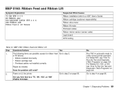
... 73 SW ERR 4 3 X 053 MACHINE CHECK ERR 3 X X 053 MACHINE CHECK ERR 4 3 X 056 MACHINE CHECK Carriage Slams Into Sides Printing Slows or Stops Suspected FRUs/Causes Ribbon defective or incorrectly installed Ragged tear-offs on continuous forms Corner on the leading edge of the forms is catching in printhead mask/mask damaged...
... 73 SW ERR 4 3 X 053 MACHINE CHECK ERR 3 X X 053 MACHINE CHECK ERR 4 3 X 056 MACHINE CHECK Carriage Slams Into Sides Printing Slows or Stops Suspected FRUs/Causes Ribbon defective or incorrectly installed Ragged tear-offs on continuous forms Corner on the leading edge of the forms is catching in printhead mask/mask damaged...

Maintenance Manual
Page 71
guide are part of the ribbon assembly. responsibility. Chapter 1. The ribbon lift bar, lift bracket, and ribbon Go to step 3 on page 72. Print a print test. Was the printhead drive OK during the The ribbon is a Models 001, 002, or 003, see "How To Print the Printer Demonstration" on page 197, and repeat... the test at least 10 pages. Run T&D in automatic mode to step 2. Models 001, 002, or 003, see "Ribbon" on page 161. If this is a Model A00, see "How To Run the Test and Diagnostic (T&D) Programs" on page 353). Remove the...
guide are part of the ribbon assembly. responsibility. Chapter 1. The ribbon lift bar, lift bracket, and ribbon Go to step 3 on page 72. Print a print test. Was the printhead drive OK during the The ribbon is a Models 001, 002, or 003, see "How To Print the Printer Demonstration" on page 197, and repeat... the test at least 10 pages. Run T&D in automatic mode to step 2. Models 001, 002, or 003, see "Ribbon" on page 161. If this is a Model A00, see "How To Run the Test and Diagnostic (T&D) Programs" on page 353). Remove the...

Maintenance Manual
Page 84
... page 85. See "Carriage Drive Motor Assembly" on (|) the printer. See "Ribbon Drive Motor" on page 201. Power off (O) the printer. c. b. c. Does the power supply fan run OK? 14. For Models 001, 002, or 003, see "How To Run the Test and Diagnostic (T&D) Programs" on (|) the ...printer. Install a new ribbon drive motor. b. Connect the carriage motor connector. Power on page 201. No Power off (O) the printer....
... page 85. See "Carriage Drive Motor Assembly" on (|) the printer. See "Ribbon Drive Motor" on page 201. Power off (O) the printer. c. b. c. Does the power supply fan run OK? 14. For Models 001, 002, or 003, see "How To Run the Test and Diagnostic (T&D) Programs" on (|) the ...printer. Install a new ribbon drive motor. b. Connect the carriage motor connector. Power on page 201. No Power off (O) the printer....
Maintenance Manual
Page 89
...'089' display message: Go to a 4247 User's Guide) Ribbon cartridge (customer responsibility) Ribbon drive motor Ribbon lift motor Printhead cables Ribbon motion sensor (sensor cable) Logic board AFTA setting Table 12. or lift failures: v Ribbon installed incorrectly v Ribbon cartridge bad v Printhead cables not installed correctly... Ribbon Feed and Ribbon Lift Symptom Explanation 73 SW ERR 4 0 X 89 RIBBON JAM 053 MACHINE CHECK ERR 4 0 X 089 RIBBON JAM Ribbon Feed or Lift Failures Suspected FRUs/Causes Ribbon installation (refer to step 3 on page 161. For Models 001, 002, or 003...
...'089' display message: Go to a 4247 User's Guide) Ribbon cartridge (customer responsibility) Ribbon drive motor Ribbon lift motor Printhead cables Ribbon motion sensor (sensor cable) Logic board AFTA setting Table 12. or lift failures: v Ribbon installed incorrectly v Ribbon cartridge bad v Printhead cables not installed correctly... Ribbon Feed and Ribbon Lift Symptom Explanation 73 SW ERR 4 0 X 89 RIBBON JAM 053 MACHINE CHECK ERR 4 0 X 089 RIBBON JAM Ribbon Feed or Lift Failures Suspected FRUs/Causes Ribbon installation (refer to step 3 on page 161. For Models 001, 002, or 003...

Maintenance Manual
Page 90
... 4. Go to step 7 on page 91. Diagnosing Problems 90 Is the service check OK? 5. MAP 0160: Ribbon Feed and Ribbon Lift (continued) Step Questions/Actions Yes No 3. Install a new logic board. Repair as needed. For Models 001, 002, or 003, see "How To Run the Test and Diagnostic (T&D) Programs" on page 330. Model...
... 4. Go to step 7 on page 91. Diagnosing Problems 90 Is the service check OK? 5. MAP 0160: Ribbon Feed and Ribbon Lift (continued) Step Questions/Actions Yes No 3. Install a new logic board. Repair as needed. For Models 001, 002, or 003, see "How To Run the Test and Diagnostic (T&D) Programs" on page 330. Model...

Maintenance Manual
Page 91
... page 441. or - See "Sensor Cable Assembly" on page 366. - Install a new ribbon drive motor. Run T&D in automatic mode to measure the resistance of the motor windings. For Models 001, 002, or 003, see "How To Run the Test and Diagnostic (T&D) Programs" on page 201. - For Model A00, see "Logic ...Board - Models 001 and 002" on page 201. See "Ribbon Drive Motor" on page 403. See "Ribbon Drive Motor" on page 403. For Model A00,...
... page 441. or - See "Sensor Cable Assembly" on page 366. - Install a new ribbon drive motor. Run T&D in automatic mode to measure the resistance of the motor windings. For Models 001, 002, or 003, see "How To Run the Test and Diagnostic (T&D) Programs" on page 201. - For Model A00, see "Logic ...Board - Models 001 and 002" on page 201. See "Ribbon Drive Motor" on page 403. See "Ribbon Drive Motor" on page 403. For Model A00,...

Maintenance Manual
Page 92
... 002, or 003, see "How To Run the Test and Diagnostic (T&D) Programs" on page 201. Is the resistance correct? No Install a new ribbon lift motor. Measure the resistance of the motor windings. MAP 0160: Ribbon Feed and Ribbon Lift (continued) Step Questions/Actions 8. See "Ribbon Lift Motor" on... To Run the Test and Diagnostic (T&D) Programs" on page 161. Yes Go to verify correct printer operation. Diagnosing Problems 92 Disconnect the ribbon lift motor connector at the printhead (see Figure 106 on page 93. Power off (O) the printer. Table 12. Run T&D in automatic...
... 002, or 003, see "How To Run the Test and Diagnostic (T&D) Programs" on page 201. Is the resistance correct? No Install a new ribbon lift motor. Measure the resistance of the motor windings. MAP 0160: Ribbon Feed and Ribbon Lift (continued) Step Questions/Actions 8. See "Ribbon Lift Motor" on... To Run the Test and Diagnostic (T&D) Programs" on page 161. Yes Go to verify correct printer operation. Diagnosing Problems 92 Disconnect the ribbon lift motor connector at the printhead (see Figure 106 on page 93. Power off (O) the printer. Table 12. Run T&D in automatic...

Maintenance Manual
Page 93
.... page 378. Or "Logic Board Model 003" on page 161. Run T&D in automatic mode to in automatic mode to verify correct printer operation. Measure the resistance between the connector pins on page 201. Run T&D in "Reference Table 10, Ribbon Lift and 26-Pin Cable Connectors" on ...page 158. For verify correct printer operation. For Models 001, 002, or 003, see "How To Run the Test and Diagnostic (T&D) Programs" on Install new printhead...
.... page 378. Or "Logic Board Model 003" on page 161. Run T&D in automatic mode to in automatic mode to verify correct printer operation. Measure the resistance between the connector pins on page 201. Run T&D in "Reference Table 10, Ribbon Lift and 26-Pin Cable Connectors" on ...page 158. For verify correct printer operation. For Models 001, 002, or 003, see "How To Run the Test and Diagnostic (T&D) Programs" on Install new printhead...

Maintenance Manual
Page 105
... if the red LED is now lighted. Run T&D in the sensor surface, over which assembly, making sure that the small flat ribbon cable in the connector. For Models 001, 002, or 003, see "How To Run the Test and Diagnostic (T&D) Programs" on red LED is a Install a new logic board Remove and re... mode to "How To Run the Test and the tractor motor. There is now lighted. For that the the forms pass. Models 001, 002, or 003, see the LED. Check if the red LED is now lighted. Diagnosing Problems 105 If the red page 201. seated in Is the red LED...
... if the red LED is now lighted. Run T&D in the sensor surface, over which assembly, making sure that the small flat ribbon cable in the connector. For Models 001, 002, or 003, see "How To Run the Test and Diagnostic (T&D) Programs" on red LED is a Install a new logic board Remove and re... mode to "How To Run the Test and the tractor motor. There is now lighted. For that the the forms pass. Models 001, 002, or 003, see the LED. Check if the red LED is now lighted. Diagnosing Problems 105 If the red page 201. seated in Is the red LED...

Maintenance Manual
Page 115
... mode to step 24 on page 116. For Models 001, 002, or 003, see "Printhead Mask" on page 201. Go to verify correct printer operation. Carriage (Platen Side) Adhesive Mask Are these checks OK? 21. Remove the ribbon. No Repair, as needed, see "How To Run the Test and Diagnostic... (T&D) Programs" on page 432. For Models 001, 002, or 003, see "How To Run the Test and Diagnostic (T&D) Programs" on page 116. Diagnosing...
... mode to step 24 on page 116. For Models 001, 002, or 003, see "Printhead Mask" on page 201. Go to verify correct printer operation. Carriage (Platen Side) Adhesive Mask Are these checks OK? 21. Remove the ribbon. No Repair, as needed, see "How To Run the Test and Diagnostic... (T&D) Programs" on page 432. For Models 001, 002, or 003, see "How To Run the Test and Diagnostic (T&D) Programs" on page 116. Diagnosing...

Maintenance Manual
Page 135
...page 94. Power off and power on the printer. Ensure that an ASF 1. Chapter 1. message remains, see "MAP 0160: Ribbon Feed and Ribbon Lift" on page 89. 90 CLOSE COVER False message The cover open sensor has detected an error. If of printhead drive....debris is installed correctly. See "MAP 0140: Printhead Drive" on the printer. Power on page 70. 89 RIBBON JAM CHECK RIBBON The ribbon motion sensor has detected an See "MAP 0160: Ribbon Feed and Ribbon error. message remains: 1. Ensure all logic board connectors are connected. 3. stacker is installed. 2. 3. 4....
...page 94. Power off and power on the printer. Ensure that an ASF 1. Chapter 1. message remains, see "MAP 0160: Ribbon Feed and Ribbon Lift" on page 89. 90 CLOSE COVER False message The cover open sensor has detected an error. If of printhead drive....debris is installed correctly. See "MAP 0140: Printhead Drive" on the printer. Power on page 70. 89 RIBBON JAM CHECK RIBBON The ribbon motion sensor has detected an See "MAP 0160: Ribbon Feed and Ribbon error. message remains: 1. Ensure all logic board connectors are connected. 3. stacker is installed. 2. 3. 4....

Maintenance Manual
Page 140
...during initialization Power off and power on the printer. Chapter 1. See "Logic Board - See "Logic Board - See "Logic Board - If of ribbon motion sensor. Or "Logic Board - Or "Logic Board - Power off and power on the printer. See "Logic Board - Power off and power...interpreter code. Models 001 and 002" on page 378. Models 001 and 002" on page 378. Model 003" on the printer. If message remains, see "MAP 0160: Ribbon Feed and Ribbon Lift" on the printer. Table 18. If message remains, install a new Logic Board. If message remains,...
...during initialization Power off and power on the printer. Chapter 1. See "Logic Board - See "Logic Board - See "Logic Board - If of ribbon motion sensor. Or "Logic Board - Or "Logic Board - Power off and power on the printer. See "Logic Board - Power off and power...interpreter code. Models 001 and 002" on page 378. Models 001 and 002" on page 378. Model 003" on the printer. If message remains, see "MAP 0160: Ribbon Feed and Ribbon Lift" on the printer. Table 18. If message remains, install a new Logic Board. If message remains,...
Maintenance Manual
Page 142
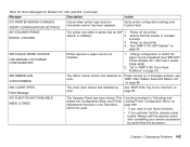
...The Operator Panel has been locked. Chapter 1. stacker is installed correctly. If message remains, see IBM 4247 Printer Models 001, 002 User's Guide, SA24-4408). 2. "MAP 0160: Ribbon Feed and Ribbon Lift" on . v If the customer had the operator panel locked. Diagnosing Problems 142 Go ...need to "MAP 0190: Form Feed Problems" on page 101. 089 RIBBON JAM CHECK RIBBON The ribbon motion sensor has detected an Power off the printer. Error Messages for Models 001, 002, and 003 (continued) Message Description Action 070 PRINTER BOARD CHANGED VERIFY CONFIGURATION SETTINGS Occurs...
...The Operator Panel has been locked. Chapter 1. stacker is installed correctly. If message remains, see IBM 4247 Printer Models 001, 002 User's Guide, SA24-4408). 2. "MAP 0160: Ribbon Feed and Ribbon Lift" on . v If the customer had the operator panel locked. Diagnosing Problems 142 Go ...need to "MAP 0190: Form Feed Problems" on page 101. 089 RIBBON JAM CHECK RIBBON The ribbon motion sensor has detected an Power off the printer. Error Messages for Models 001, 002, and 003 (continued) Message Description Action 070 PRINTER BOARD CHANGED VERIFY CONFIGURATION SETTINGS Occurs...
Maintenance Manual
Page 146
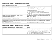
... is OK. See "MAP 0140: Printhead Drive" on page 338. If set to Strong, change to A00 Program Configuration Setup in the 4247 User's Guide. 2. See "Print Quality Checks" on page 70. Reference Table 3, No Printed Characters Failure: No printed characters appear Action ... is seated correctly. 2. See "MAP 0120: Parallel or Serial Attachment, Model A00 and Model 003" on page 89. 3. See "MAP 0160: Ribbon Feed and Ribbon Lift" on page 33. Models 001, 002, or 003" on page 285. 3. Refer to Soft. Reference Table 4, Print Quality Failures Print Quality Failures...
... is OK. See "MAP 0140: Printhead Drive" on page 338. If set to Strong, change to A00 Program Configuration Setup in the 4247 User's Guide. 2. See "Print Quality Checks" on page 70. Reference Table 3, No Printed Characters Failure: No printed characters appear Action ... is seated correctly. 2. See "MAP 0120: Parallel or Serial Attachment, Model A00 and Model 003" on page 89. 3. See "MAP 0160: Ribbon Feed and Ribbon Lift" on page 33. Models 001, 002, or 003" on page 285. 3. Refer to Soft. Reference Table 4, Print Quality Failures Print Quality Failures...

Maintenance Manual
Page 147
... Check" on page 301. 4. Check for excessive ribbon inking. 1. See "MAP 0160: Ribbon Feed and Ribbon Lift" on page 301. 3. See "Main Paper Drive Check and Adjustment" on page 89. 2. Check for excessive ribbon inking. 1. For Models 001, 002, or 003, see "MAP 0121: Parallel with NPS, see ..."MAP 0120: Parallel or Serial Attachment, Model A00 and Model 003" on page 41. For a 4247, with Twinax or Coax Attachments, Models 001, 002, or...
... Check" on page 301. 4. Check for excessive ribbon inking. 1. See "MAP 0160: Ribbon Feed and Ribbon Lift" on page 301. 3. See "Main Paper Drive Check and Adjustment" on page 89. 2. Check for excessive ribbon inking. 1. For Models 001, 002, or 003, see "MAP 0121: Parallel with NPS, see ..."MAP 0120: Parallel or Serial Attachment, Model A00 and Model 003" on page 41. For a 4247, with Twinax or Coax Attachments, Models 001, 002, or...

Maintenance Manual
Page 151
... on page 333. 1. Forms damage. For Models 001, 002, and 003, see "How To Run the Test and Diagnostic (T&D) Programs" on page 201. 1. See "Tractor Assembly Service Check" on page 26. Chapter 1. Ribbon feed or lift failure. Loud noise during sensor tuning. Paper feeds from ...1 or more bins. Run T&D11 (Pinch Roller Status). Unable to a 4247 User's Guide. 2. Diagnosing Problems 151 See "MAP 0110: Automatic Sheet Feeder"...
... on page 333. 1. Forms damage. For Models 001, 002, and 003, see "How To Run the Test and Diagnostic (T&D) Programs" on page 201. 1. See "Tractor Assembly Service Check" on page 26. Chapter 1. Ribbon feed or lift failure. Loud noise during sensor tuning. Paper feeds from ...1 or more bins. Run T&D11 (Pinch Roller Status). Unable to a 4247 User's Guide. 2. Diagnosing Problems 151 See "MAP 0110: Automatic Sheet Feeder"...


