
Service Guide
Page 6
... problems 127 Hard disk drive problems 127 Intermittent problems 128 USB keyboard, mouse, or pointing-device problems 129 Memory problems 130 Microprocessor problems 131 iv IBM System x3655 Type 7985: Problem Determination and Service Guide Parts listing, System x3655, Type 7985 97 Replaceable server components 97 Power cords 103 Chapter 5. Removing a hard disk drive 52 Installing a hard disk...
... problems 127 Hard disk drive problems 127 Intermittent problems 128 USB keyboard, mouse, or pointing-device problems 129 Memory problems 130 Microprocessor problems 131 iv IBM System x3655 Type 7985: Problem Determination and Service Guide Parts listing, System x3655, Type 7985 97 Replaceable server components 97 Power cords 103 Chapter 5. Removing a hard disk drive 52 Installing a hard disk...
Service Guide
Page 22
... IDE drives: - Maximum: 127 V ac v Support for one of the following riser cards: - Features and specifications The following configurations: - Memory: v Sixteen DIMM connectors v Minimum: 1 GB v Maximum: 64 GB v Type: Registered PC2-5300 double data rate (DDR) II, DIMMs... 240 V ac v Input kilovolt-amperes (kVA) approximately: - Six 3.5-inch drive bays (optional tape drive will operate. 4 IBM System x3655 Type 7985: Problem Determination and Service Guide PCI-X riser card with battery backup, the power-management optional features in Acoustical noise emissions: v Declared...
... IDE drives: - Maximum: 127 V ac v Support for one of the following riser cards: - Features and specifications The following configurations: - Memory: v Sixteen DIMM connectors v Minimum: 1 GB v Maximum: 64 GB v Type: Registered PC2-5300 double data rate (DDR) II, DIMMs... 240 V ac v Input kilovolt-amperes (kVA) approximately: - Six 3.5-inch drive bays (optional tape drive will operate. 4 IBM System x3655 Type 7985: Problem Determination and Service Guide PCI-X riser card with battery backup, the power-management optional features in Acoustical noise emissions: v Declared...
Service Guide
Page 35
... the following configuration programs to detect the server model and optional hardware devices that is available for your IBM server. v BIOS code is stored in memory on the IBM System x Documentation CD. v SAS firmware is stored in ROM on the Web. v Ethernet firmware is ...stored in ROM on the system board. Chapter 2. Adaptec RAID Configuration Utility program - Using the ServerGuide Setup and ...
... the following configuration programs to detect the server model and optional hardware devices that is available for your IBM server. v BIOS code is stored in memory on the IBM System x Documentation CD. v SAS firmware is stored in ROM on the Web. v Ethernet firmware is ...stored in ROM on the system board. Chapter 2. Adaptec RAID Configuration Utility program - Using the ServerGuide Setup and ...

Service Guide
Page 57
Cover-release latch 4. Removing and replacing server components 39 If IBM installs a Tier 1 CRU at your hardware. Note: You can reach the cables on page 35. 2. Lift the cover-release latch. Lift the cover off the ..., follow all external cables and power cords. 3. Chapter 3. To remove the cover, complete the following steps: 1. If you are supplied to install or remove a microprocessor, memory module, PCI adapter, or tape drive, turn off the server and set the cover aside. 5. Press down on the server. Removing the cover Attention: For...
Cover-release latch 4. Removing and replacing server components 39 If IBM installs a Tier 1 CRU at your hardware. Note: You can reach the cables on page 35. 2. Lift the cover-release latch. Lift the cover off the ..., follow all external cables and power cords. 3. Chapter 3. To remove the cover, complete the following steps: 1. If you are supplied to install or remove a microprocessor, memory module, PCI adapter, or tape drive, turn off the server and set the cover aside. 5. Press down on the server. Removing the cover Attention: For...

Service Guide
Page 80
... and 10 6 DIMM connectors 1 through 6 DIMM connectors 1 through 4 and 9 and 10 62 IBM System x3655 Type 7985: Problem Determination and Service Guide Remove the riser-card assembly (see "Removing the air baffle" on the IBM System x Documentation CD. Disconnect all attached devices. 3. Remove the cover (see the User's Guide on ... or remove the second DIMM of the DIMM connector and lift the DIMM from the connector. 8. Installing a memory module For information about the types of two 512 MB DIMMs, installed in the following steps. Read the safety information that you .
... and 10 6 DIMM connectors 1 through 6 DIMM connectors 1 through 4 and 9 and 10 62 IBM System x3655 Type 7985: Problem Determination and Service Guide Remove the riser-card assembly (see "Removing the air baffle" on the IBM System x Documentation CD. Disconnect all attached devices. 3. Remove the cover (see the User's Guide on ... or remove the second DIMM of the DIMM connector and lift the DIMM from the connector. 8. Installing a memory module For information about the types of two 512 MB DIMMs, installed in the following steps. Read the safety information that you .

Service Guide
Page 81
...pairs of DIMMs to replace the failed pair. The DIMMs must be installed to your DIMM configuration. The BIOS code assigns the online-spare memory DIMM pairs according to support online sparing. Table 3. Online-sparing is supported on a per processor basis. DIMM installation sequence (continued) DIMMs...through 8 and 9 through 14 DIMM connectors 1 through the Configuration/Setup Utility program. This feature disables a failed pair of DIMMS from the system configuration and activates an online-spare pair of DIMMs be the same speed, type, size (or larger), and technology as the failed pair ...
...pairs of DIMMs to replace the failed pair. The DIMMs must be installed to your DIMM configuration. The BIOS code assigns the online-spare memory DIMM pairs according to support online sparing. Table 3. Online-sparing is supported on a per processor basis. DIMM installation sequence (continued) DIMMs...through 8 and 9 through 14 DIMM connectors 1 through the Configuration/Setup Utility program. This feature disables a failed pair of DIMMS from the system configuration and activates an online-spare pair of DIMMs be the same speed, type, size (or larger), and technology as the failed pair ...

Service Guide
Page 112
... a mismatch between the microprocessor and its microprocessor for shipping that the customer provides on a diskette or CD image. 94 IBM System x3655 Type 7985: Problem Determination and Service Guide Attention: In the following step, do not allow the thermal grease to come in contact with...heat sink paired with any packaging materials for reinstallation. Lift the shuttle out of the server (see "Removing a memory module" on page 62). 7. Installing the system board and shuttle Notes: 1. then, place them on a static-protective surface for reinstallation (see "Removing the ...
... a mismatch between the microprocessor and its microprocessor for shipping that the customer provides on a diskette or CD image. 94 IBM System x3655 Type 7985: Problem Determination and Service Guide Attention: In the following step, do not allow the thermal grease to come in contact with...heat sink paired with any packaging materials for reinstallation. Lift the shuttle out of the server (see "Removing a memory module" on page 62). 7. Installing the system board and shuttle Notes: 1. then, place them on a static-protective surface for reinstallation (see "Removing the ...

Service Guide
Page 113
...and the server. Turn on page 83). 3. Chapter 3. Install the server cover (see "Installing a memory module" on page 69). 4. To install the replacement system board and shuttle, complete the following steps: Shuttle release latch Shuttle assembly 1. Install each microprocessor with the ...protrusions in place. 2. then, slide the shuttle toward the system board until it clicks into place. Install the power supplies (see "Installing a microprocessor" on page 93. 5. Align the openings...
...and the server. Turn on page 83). 3. Chapter 3. Install the server cover (see "Installing a memory module" on page 69). 4. To install the replacement system board and shuttle, complete the following steps: Shuttle release latch Shuttle assembly 1. Install each microprocessor with the ...protrusions in place. 2. then, slide the shuttle toward the system board until it clicks into place. Install the power supplies (see "Installing a microprocessor" on page 93. 5. Align the openings...
Service Guide
Page 118
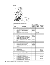
...11x, 41Y2758 12x, 1Ax, 1Bx, 21x, 2Ax, 41x, 4Ax, 51x, 5Ax, 61x, 6Ax, E1x, E2x, E4x, E5x) 4 Memory, 1GB PC2-5300 (models EBx, ECx, 41Y2761 EDx) 4 Memory, 2 GB PC2-5300 (optional) 41Y2764 4 Memory, 4 GB PC2-5300 (optional) 41Y2851 5 ServeRAID-8k-l SAS Controller 25R8079 5 ServeRAID-8k SAS Controller with battery 25R8076 (optional) 6 Heat... 43W7268 9 Microprocessor, 2.0 GHz, dual core w/heatsink (models 21x, 2Ax, E2x, EBx) 40K7549 9 Microprocessor, 2.4 GHz, dual core w/heatsink (models 41x, 4Ax, E4x, ECx) 40K7550 100 IBM System x3655 Type 7985: Problem Determination and Service Guide
...11x, 41Y2758 12x, 1Ax, 1Bx, 21x, 2Ax, 41x, 4Ax, 51x, 5Ax, 61x, 6Ax, E1x, E2x, E4x, E5x) 4 Memory, 1GB PC2-5300 (models EBx, ECx, 41Y2761 EDx) 4 Memory, 2 GB PC2-5300 (optional) 41Y2764 4 Memory, 4 GB PC2-5300 (optional) 41Y2851 5 ServeRAID-8k-l SAS Controller 25R8079 5 ServeRAID-8k SAS Controller with battery 25R8076 (optional) 6 Heat... 43W7268 9 Microprocessor, 2.0 GHz, dual core w/heatsink (models 21x, 2Ax, E2x, EBx) 40K7549 9 Microprocessor, 2.4 GHz, dual core w/heatsink (models 41x, 4Ax, E4x, ECx) 40K7550 100 IBM System x3655 Type 7985: Problem Determination and Service Guide
Service Guide
Page 120
... 40K7563 Kit, misc., label, 7985 40K7564 Kit, cable management arm 40K6556 Kit, tape enablement 40K6449 LSI, 256 card assembly (optional 39R8852 LSI card assembly (optional) 25R8071 Myrinet E PCI-X adapter (optional) 40K8751 Myrinet 333 MHz single fiber/PCI-X ″F″ adapter with 2MB memory card assembly (optional) 40K8753 Myrinet... adapter 42C1772 (optional) Rack power cord, 1.8 M 39M5074 Rack power cord, 2.8 M 39M5082 Rack power cord, 1.8 M 39M5115 Rack power cord, 2.8 M 39M5116 102 IBM System x3655 Type 7985: Problem Determination and Service Guide Table 5.
... 40K7563 Kit, misc., label, 7985 40K7564 Kit, cable management arm 40K6556 Kit, tape enablement 40K6449 LSI, 256 card assembly (optional 39R8852 LSI card assembly (optional) 25R8071 Myrinet E PCI-X adapter (optional) 40K8751 Myrinet 333 MHz single fiber/PCI-X ″F″ adapter with 2MB memory card assembly (optional) 40K8753 Myrinet... adapter 42C1772 (optional) Rack power cord, 1.8 M 39M5074 Rack power cord, 2.8 M 39M5082 Rack power cord, 1.8 M 39M5115 Rack power cord, 2.8 M 39M5116 102 IBM System x3655 Type 7985: Problem Determination and Service Guide Table 5.
Service Guide
Page 125
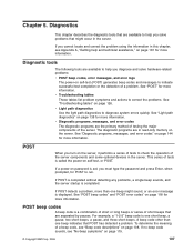
...page 138 for more information. A beep code other than one beep might occur in read-only memory on the server. See "Light path diagnostics" on self-test, or POST. If no beep... to correct the problems. See "Troubleshooting tables" on page 181 for POST to diagnose system errors quickly. Diagnostics This chapter describes the diagnostic tools that might sound, or an error... v POST beep codes, error messages, and error logs The power-on page 115. © Copyright IBM Corp. 2006 107 See "Diagnostic programs, messages, and error codes" on page 118 for more than one...
...page 138 for more information. A beep code other than one beep might occur in read-only memory on the server. See "Light path diagnostics" on self-test, or POST. If no beep... to correct the problems. See "Troubleshooting tables" on page 181 for POST to diagnose system errors quickly. Diagnostics This chapter describes the diagnostic tools that might sound, or an error... v POST beep codes, error messages, and error logs The power-on page 115. © Copyright IBM Corp. 2006 107 See "Diagnostic programs, messages, and error codes" on page 118 for more than one...

Service Guide
Page 128
... a time, in the order shown, restarting the server each time. DIMMs b. (Trained service technician only) System board 110 IBM System x3655 Type 7985: Problem Determination and Service Guide a. screen believed operable. (Trained service technician only) Replace the system board. 2-4-4 Unsupported memory configuration. 1. Replace the following components one at a time, in the order shown, restarting the server each...
... a time, in the order shown, restarting the server each time. DIMMs b. (Trained service technician only) System board 110 IBM System x3655 Type 7985: Problem Determination and Service Guide a. screen believed operable. (Trained service technician only) Replace the system board. 2-4-4 Unsupported memory configuration. 1. Replace the following components one at a time, in the order shown, restarting the server each...

Service Guide
Page 129
... Reseat the DIMMs. 2. Battery c. (Trained service technician only) System board 3-3-2 Critical SMBUS error occurred. 1. v See Chapter 4, "Parts listing, System x3655, Type 7985," on page 97 to determine which components are customer replaceable units... (CRU) and which they are field replaceable units (FRU). Battery b. (Trained service technician only) System board 3-2-1 Serial port failed. (Trained service technician only) Replace the system board. 3-2-4 Failure comparing CMOS memory...
... Reseat the DIMMs. 2. Battery c. (Trained service technician only) System board 3-3-2 Critical SMBUS error occurred. 1. v See Chapter 4, "Parts listing, System x3655, Type 7985," on page 97 to determine which components are customer replaceable units... (CRU) and which they are field replaceable units (FRU). Battery b. (Trained service technician only) System board 3-2-1 Serial port failed. (Trained service technician only) Replace the system board. 3-2-4 Failure comparing CMOS memory...

Service Guide
Page 130
...only by a blank display screen. Install or reseat DIMMS and restart the server. 2. Run the Configuration/Setup Utility program. 112 IBM System x3655 Type 7985: Problem Determination and Service Guide v Follow the suggested actions in the order in which components are listed in the Action column until... "(Trained service technician only)," that step must restart the server three times to force the system BIOS to reset the CMOS values to the default configuration (memory connector or bank of the Configuration/Setup Utility program is set to determine which components are customer...
...only by a blank display screen. Install or reseat DIMMS and restart the server. 2. Run the Configuration/Setup Utility program. 112 IBM System x3655 Type 7985: Problem Determination and Service Guide v Follow the suggested actions in the order in which components are listed in the Action column until... "(Trained service technician only)," that step must restart the server three times to force the system BIOS to reset the CMOS values to the default configuration (memory connector or bank of the Configuration/Setup Utility program is set to determine which components are customer...

Service Guide
Page 131
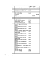
Beep code Description Action Three short beeps Memory error. 1. b. Beginning with an identical known good DIMM, restarting the server after each time...returns. d. If the beep code error remains after each time: a. DIMMs b. (Trained service technician only) System board Chapter 5. Diagnostics 113 e. Remove all memory banks. 3. Locate the failing DIMMs: a. Replace the following components one pair of known good DIMMs, restarting ... error returns. v If an action step is solved. v See Chapter 4, "Parts listing, System x3655, Type 7985," on page 97 to step 3b.
Beep code Description Action Three short beeps Memory error. 1. b. Beginning with an identical known good DIMM, restarting the server after each time...returns. d. If the beep code error remains after each time: a. DIMMs b. (Trained service technician only) System board Chapter 5. Diagnostics 113 e. Remove all memory banks. 3. Locate the failing DIMMs: a. Replace the following components one pair of known good DIMMs, restarting ... error returns. v If an action step is solved. v See Chapter 4, "Parts listing, System x3655, Type 7985," on page 97 to step 3b.

Service Guide
Page 137
...which components are customer replaceable units (CRU) and which they are field replaceable units (FRU). v See Chapter 4, "Parts listing, System x3655, Type 7985," on the serial port. 2. If the DIMM was just installed has a supported power rating. Update BIOS code and rerun diagnostics.... 2. Update BIOS code. 3. (Trained service technician only) Replace the system board. 201 Memory test error. 1. Replace the following components one at...
...which components are customer replaceable units (CRU) and which they are field replaceable units (FRU). v See Chapter 4, "Parts listing, System x3655, Type 7985," on the serial port. 2. If the DIMM was just installed has a supported power rating. Update BIOS code and rerun diagnostics.... 2. Update BIOS code. 3. (Trained service technician only) Replace the system board. 201 Memory test error. 1. Replace the following components one at...

Service Guide
Page 138
...units (CRU) and which they are listed in the Action column until the problem is isolated. 1801 An adapter has requested memory resources that step must be performed only by the serial port are available. 2. Select Advanced Setup to disable any of adapters...IRQ and I /O Ports to disable the option ROM of the integrated devices. 4. Each adapter b. (Trained service technician only) System board 120 IBM System x3655 Type 7985: Problem Determination and Service Guide Run the Configuration/Setup Utility program and load the defaults. 3. Error code Description Action 1162 Serial ...
...units (CRU) and which they are listed in the Action column until the problem is isolated. 1801 An adapter has requested memory resources that step must be performed only by the serial port are available. 2. Select Advanced Setup to disable any of adapters...IRQ and I /O Ports to disable the option ROM of the integrated devices. 4. Each adapter b. (Trained service technician only) System board 120 IBM System x3655 Type 7985: Problem Determination and Service Guide Run the Configuration/Setup Utility program and load the defaults. 3. Error code Description Action 1162 Serial ...

Service Guide
Page 139
...shown, restarting the server each time: a. Video adapter (if installed) b. (Trained service technician only) System board 2462 Video memory configuration error. (Trained service technician only) Replace the system board. 5962 IDE CD or DVD drive configuration error. 1. CD or DVD drive IDE cable c. SAS... the Configuration/Setup Utility program, select Load Default Settings, and save the settings. 2. v See Chapter 4, "Parts listing, System x3655, Type 7985," on page 97 to determine which components are customer replaceable units (CRU) and which they are field replaceable units (FRU). Hard ...
...shown, restarting the server each time: a. Video adapter (if installed) b. (Trained service technician only) System board 2462 Video memory configuration error. (Trained service technician only) Replace the system board. 5962 IDE CD or DVD drive configuration error. 1. CD or DVD drive IDE cable c. SAS... the Configuration/Setup Utility program, select Load Default Settings, and save the settings. 2. v See Chapter 4, "Parts listing, System x3655, Type 7985," on page 97 to determine which components are customer replaceable units (CRU) and which they are field replaceable units (FRU). Hard ...

Service Guide
Page 148
... the server after all removed DIMMs. 4. (Trained service technician only) Replace the system board. 130 IBM System x3655 Type 7985: Problem Determination and Service Guide Return the removed DIMMs, one at a time, to step 4. 3. Run memory diagnostics (see "Installing a memory module" on page 62. 6. Memory problems v Follow the suggested actions in the order in which components are field...
... the server after all removed DIMMs. 4. (Trained service technician only) Replace the system board. 130 IBM System x3655 Type 7985: Problem Determination and Service Guide Return the removed DIMMs, one at a time, to step 4. 3. Run memory diagnostics (see "Installing a memory module" on page 62. 6. Memory problems v Follow the suggested actions in the order in which components are field...

Service Guide
Page 150
...switch to the correct connector on page 144). If there is turned on page 177 for information about solving undetermined problems. 132 IBM System x3655 Type 7985: Problem Determination and Service Guide Remote Supervisor Adapter II SlimLine (if one at a time, in the order shown, restarting the... blank. 1. Make sure that step must restart the server three times to reset the configuration settings to the default configuration (the memory connector or bank of the problem: connect the monitor cable directly to eliminate it as a possible cause of connectors enabled). 3. ...
...switch to the correct connector on page 144). If there is turned on page 177 for information about solving undetermined problems. 132 IBM System x3655 Type 7985: Problem Determination and Service Guide Remote Supervisor Adapter II SlimLine (if one at a time, in the order shown, restarting the... blank. 1. Make sure that step must restart the server three times to reset the configuration settings to the default configuration (the memory connector or bank of the problem: connect the monitor cable directly to eliminate it as a possible cause of connectors enabled). 3. ...


