

Product Datasheet
Page 2
..., RTSP, RTP, SMTP, NTP, DHCP, DNS, FTP, QoS ONVIF CGI 10 users iPhone, iPad, Android, Windows Phone Tilt: 0° ~ 90° 100°/s 25 8 Video H.264 / H.264B / MJPEG 720P (1280×720) / D1 / CIF Main Stream - 720P (1~25/30fps) Sub Stream - LEDs Length Day/Night Backlight Compensation White Balance Gain Control Noise Reduction Flip Focal Length Max Aperture Focus Control Angle of View Lens Type Mount Type Pan/Tilt Range Preset Speed Preset Tour Compression Resolution...
..., RTSP, RTP, SMTP, NTP, DHCP, DNS, FTP, QoS ONVIF CGI 10 users iPhone, iPad, Android, Windows Phone Tilt: 0° ~ 90° 100°/s 25 8 Video H.264 / H.264B / MJPEG 720P (1280×720) / D1 / CIF Main Stream - 720P (1~25/30fps) Sub Stream - LEDs Length Day/Night Backlight Compensation White Balance Gain Control Noise Reduction Flip Focal Length Max Aperture Focus Control Angle of View Lens Type Mount Type Pan/Tilt Range Preset Speed Preset Tour Compression Resolution...

Product Datasheet
Page 3
Memory Slot Power Supply Power Consumption Working Environment Dimensions Weight Auxiliary Interface Micro SD, Max 64GB General DC 5V2A (POWER SUPPLY INCLUDED)
Memory Slot Power Supply Power Consumption Working Environment Dimensions Weight Auxiliary Interface Micro SD, Max 64GB General DC 5V2A (POWER SUPPLY INCLUDED)

Product Manual
Page 2
... time; Please don't keep this start guide is for your local electrical safety codes. Please prevent the line cord from being trampled or pressed, especially the plug, power socket and the junction from the device. Please keep the sound ventilation in accordance with same quality when transporting the device. Please check if the power supply is correct before installing wiring...
... time; Please don't keep this start guide is for your local electrical safety codes. Please prevent the line cord from being trampled or pressed, especially the plug, power socket and the junction from the device. Please keep the sound ventilation in accordance with same quality when transporting the device. Please check if the power supply is correct before installing wiring...

Product Manual
Page 3
...to the following methods to avoid scald. It is not clean enough. Finally use it to change the cloth and wipe several times if it is not stable and so on the lens surface. the manual is installed and fixed by users themselves in the machine. The grounding holes of the device. Stained with ...lens center to outward. there is no component which is not followed by alcohol to wipe away the dust gently if it is ok to clean the device. It may cause water leakage or bad image for the device due to the actual product for more power supply modes for any problem occurred when using...
...to the following methods to avoid scald. It is not clean enough. Finally use it to change the cloth and wipe several times if it is not stable and so on the lens surface. the manual is installed and fixed by users themselves in the machine. The grounding holes of the device. Stained with ...lens center to outward. there is no component which is not followed by alcohol to wipe away the dust gently if it is ok to clean the device. It may cause water leakage or bad image for the device due to the actual product for more power supply modes for any problem occurred when using...
Product Manual
Page 4
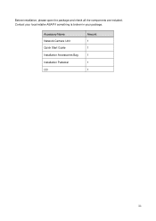
Accessory Name Network Camera Unit Quick Start Guide Installation Accessories Bag Installation Pedestal CD Amount 1 1 1 1 1 iii Contact your local retailer ASAP if something is broken in your package. Before installation, please open the package and check all the components are included.
Accessory Name Network Camera Unit Quick Start Guide Installation Accessories Bag Installation Pedestal CD Amount 1 1 1 1 1 iii Contact your local retailer ASAP if something is broken in your package. Before installation, please open the package and check all the components are included.
Product Manual
Page 5
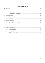
Table of Contents 1 Structure ...1 1.1 Structure Info...1 1.2 Framework and Dimension 2 2 Device Installation ...4 2.1 Installation Steps ...4 3 Device Configuration...5 3.1 Device Configuration Steps 5 3.2 Restore Factory Default Setup Introduction 8 4 Network Configuration ...9 4.1 Modify IP Address ...9 4.2 Login WEB Interface 10 iv
Table of Contents 1 Structure ...1 1.1 Structure Info...1 1.2 Framework and Dimension 2 2 Device Installation ...4 2.1 Installation Steps ...4 3 Device Configuration...5 3.1 Device Configuration Steps 5 3.2 Restore Factory Default Setup Introduction 8 4 Network Configuration ...9 4.1 Modify IP Address ...9 4.2 Login WEB Interface 10 iv
Product Manual
Page 6
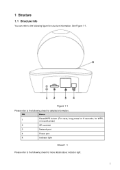
See Figure 1-1. SN Name 1 Reset/WPS button (For reset, long press for structure information. 1 Structure 1.1 Structure Info You can refer to the following sheet for more details about indicator light. 1 for WPS, one quick press) 2 SD card slot 3 Network port 4 Power port 5 Indicator light Sheet 1-1 Please refer to the following sheet for detailed information. Figure 1-1 Please refer to the following figure for 8 seconds;
See Figure 1-1. SN Name 1 Reset/WPS button (For reset, long press for structure information. 1 Structure 1.1 Structure Info You can refer to the following sheet for more details about indicator light. 1 for WPS, one quick press) 2 SD card slot 3 Network port 4 Power port 5 Indicator light Sheet 1-1 Please refer to the following sheet for detailed information. Figure 1-1 Please refer to the following figure for 8 seconds;
Product Manual
Page 7
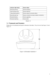
See Figure 1-2 and Figure 1-3. Figure 1-2 Dimension illustration 1 2 The unit is mm. Indicator light status Red light spinning Device status Device activating Green light spinning Device matching Yellow light breathing Device network connection failure Blue light spinning Device connection success (network connection) Red light flashing Red light breathing Device upgrading Device alarm Sheet 1-2 1.2 Framework and Dimension Please refer to the following two figures for dimension information.
See Figure 1-2 and Figure 1-3. Figure 1-2 Dimension illustration 1 2 The unit is mm. Indicator light status Red light spinning Device status Device activating Green light spinning Device matching Yellow light breathing Device network connection failure Blue light spinning Device connection success (network connection) Red light flashing Red light breathing Device upgrading Device alarm Sheet 1-2 1.2 Framework and Dimension Please refer to the following two figures for dimension information.

Product Manual
Page 9
2 Device Installation 2.1 Installation Steps Important Before the installation, please make sure the installation environments can at least support 3x weight of the camera. Figure 2-1 4
2 Device Installation 2.1 Installation Steps Important Before the installation, please make sure the installation environments can at least support 3x weight of the camera. Figure 2-1 4
Product Manual
Page 10
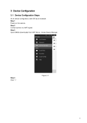
Step 4 Click "+". 3 Device Configuration 3.1 Device Configuration Steps As for device configuration, take IOS as an example. Step 1 Power on the camera. Step 2 Connect iphone to a WiFi signal. Figure 3-1 5 Step 3 Open DMSS (downloaded from APP Store), choose Device Manager.
Step 4 Click "+". 3 Device Configuration 3.1 Device Configuration Steps As for device configuration, take IOS as an example. Step 1 Power on the camera. Step 2 Connect iphone to a WiFi signal. Figure 3-1 5 Step 3 Open DMSS (downloaded from APP Store), choose Device Manager.

Product Manual
Page 11
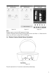
Step 5 Choose "WiFi configuration". Figure 3-2 Figure 3-3 Step 6 Input a device name and scan the QR code on camera, then "next". 6
Step 5 Choose "WiFi configuration". Figure 3-2 Figure 3-3 Step 6 Input a device name and scan the QR code on camera, then "next". 6

Product Manual
Page 12
Step 7 Input the WiFi password, then "next". Figure 3-4 Step 8 Connection succeeds. Figure 3-5 7
Step 7 Input the WiFi password, then "next". Figure 3-4 Step 8 Connection succeeds. Figure 3-5 7
Product Manual
Page 13
The WiFi configuration will be closed if activating WPS function (see Sheet 1-1), Please reset the device if you still need to configure WiFi via DMSS App. 3.2 Restore Factory Default Setup Introduction Figure 3-9 Press the reset button for 10 seconds to restore factory default setup. 8 Figure 3-6 Figure 3-7 Figure 3-8 Note: Please try again or check the WiFi password if it failed.
The WiFi configuration will be closed if activating WPS function (see Sheet 1-1), Please reset the device if you still need to configure WiFi via DMSS App. 3.2 Restore Factory Default Setup Introduction Figure 3-9 Press the reset button for 10 seconds to restore factory default setup. 8 Figure 3-6 Figure 3-7 Figure 3-8 Note: Please try again or check the WiFi password if it failed.
Product Manual
Page 14
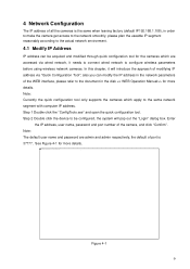
... supports the cameras which apply to be acquired and modified through quick configuration tool for the cameras which are admin and admin respectively, the default of port is the same when leaving factory (default IP192.168.1.108), in the disk > for more details. Note: The default user name and password are accessed via "Quick Configuration Tool"; also you can modify the IP address in the network parameters of the WEB...
... supports the cameras which apply to be acquired and modified through quick configuration tool for the cameras which are admin and admin respectively, the default of port is the same when leaving factory (default IP192.168.1.108), in the disk > for more details. Note: The default user name and password are accessed via "Quick Configuration Tool"; also you can modify the IP address in the network parameters of the WEB...

Product Manual
Page 15
Figure 4-2 4.2 Login WEB Interface Note: Different devices may have different WEB interfaces, the figures below , please input your user name and password (Default user name is admin and password is shown below are just for reference, please refer to finish modification. See Figure 4-2 for more details Step 1 Open IE and input the modified camera IP address in the disk and the actual...
Figure 4-2 4.2 Login WEB Interface Note: Different devices may have different WEB interfaces, the figures below , please input your user name and password (Default user name is admin and password is shown below are just for reference, please refer to finish modification. See Figure 4-2 for more details Step 1 Open IE and input the modified camera IP address in the disk and the actual...

Product Manual
Page 16
Figure 4-4 11 Figure 4-3 Step 3 Install controls according to the system prompt; Please modify the administrator password as soon as possible after you successfully logged in. see Figure 4-4 for the WEB main interface.
Figure 4-4 11 Figure 4-3 Step 3 Install controls according to the system prompt; Please modify the administrator password as soon as possible after you successfully logged in. see Figure 4-4 for the WEB main interface.

Product Manual
Page 17
Note: This quick start guide is any uncertainty or controversy, please refer to change without prior written notice. All trademarks and registered trademarks mentioned are the properties of us. Please visit our website or contact your local service engineer for reference only. Slight difference may be found in user interface. All the designs and software here are subject to the final explanation of their respective owners. If there is for more information. 12
Note: This quick start guide is any uncertainty or controversy, please refer to change without prior written notice. All trademarks and registered trademarks mentioned are the properties of us. Please visit our website or contact your local service engineer for reference only. Slight difference may be found in user interface. All the designs and software here are subject to the final explanation of their respective owners. If there is for more information. 12


