Product Datasheet
Page 1
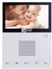
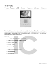
.../100Mbps self-adaptive Ethernet Device-to make emergency calls directly from the unit add layers of safety and convenience. IH-D7210 7-Inch Touch LED Screen Network Intercom System This indoor intercom station makes client safety a priority. It features a 7" touch screen and two-way audio so that visitors can be vetted before being granted entry. For best results, pair this unit...
.../100Mbps self-adaptive Ethernet Device-to make emergency calls directly from the unit add layers of safety and convenience. IH-D7210 7-Inch Touch LED Screen Network Intercom System This indoor intercom station makes client safety a priority. It features a 7" touch screen and two-way audio so that visitors can be vetted before being granted entry. For best results, pair this unit...
Product Datasheet
Page 2
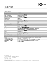
... Network Protocol Power Power Consumption Working Environment Dimensions (L×W×T) Weight IH-D7210 System Built-in microcontroller Embedded LINUX Video H.264 800×480 Audio All-direction Microphone Embedded loudspeaker Supported Display Color 7-inch TFT LCD Operating Modes Mechanical keys(emergency, protection, video talk, monitoring,unlock ), Touch screen technology Alarm 8 channels Network 10 M / 100 Mbps adaptive TCP/IP General DC 10~15V or supply directly by Special switching power Standby: ≤...
... Network Protocol Power Power Consumption Working Environment Dimensions (L×W×T) Weight IH-D7210 System Built-in microcontroller Embedded LINUX Video H.264 800×480 Audio All-direction Microphone Embedded loudspeaker Supported Display Color 7-inch TFT LCD Operating Modes Mechanical keys(emergency, protection, video talk, monitoring,unlock ), Touch screen technology Alarm 8 channels Network 10 M / 100 Mbps adaptive TCP/IP General DC 10~15V or supply directly by Special switching power Standby: ≤...
Product Manual
Page 2
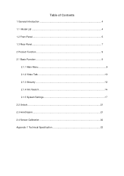
Table of Contents 1 General Introduction 4 1.1 Model List ...4 1.2 Front Panel ...5 1.3 Rear Panel...7 2 Product Function ...9 2.1 Basic Function ...9 2.1.1 Main Menu...9 2.1.2 Video Talk...10 2.1.3 Security ...12 2.1.4 Info Search ...14 2.1.5 System Settings 17 2.2 Unlock ...21 2.3 Arm/Disarm...21 2.4 Screen Calibration 22 Appendix 1 Technical Specification 23
Table of Contents 1 General Introduction 4 1.1 Model List ...4 1.2 Front Panel ...5 1.3 Rear Panel...7 2 Product Function ...9 2.1 Basic Function ...9 2.1.1 Main Menu...9 2.1.2 Video Talk...10 2.1.3 Security ...12 2.1.4 Info Search ...14 2.1.5 System Settings 17 2.2 Unlock ...21 2.3 Arm/Disarm...21 2.4 Screen Calibration 22 Appendix 1 Technical Specification 23

Product Manual
Page 3
...change without prior written notice. owners. If there is any object on the device. Do not disassemble the device without professional instruction. Please use power line other dangers. Please replace used battery with battery of the same type. Do not use it may cause fire or electric... the final explanation of the device or ventilation around the device. Otherwise, it may cause fire or electric shock. Do not install the device at position exposed to humid environment. Otherwise, temperature in device will rise and may cause...
...change without prior written notice. owners. If there is any object on the device. Do not disassemble the device without professional instruction. Please use power line other dangers. Please replace used battery with battery of the same type. Do not use it may cause fire or electric... the final explanation of the device or ventilation around the device. Otherwise, it may cause fire or electric shock. Do not install the device at position exposed to humid environment. Otherwise, temperature in device will rise and may cause...
Product Manual
Page 4
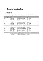
...touch screen Not support VTH1520AH Resistive touch screen Support AS VTH1510AS Resistive touch screen Not support AS-H VTH1520AS VTH1510AS-H Resistive touch screen Resistive touch screen Support Not support VTH1520AS-H Resistive touch screen Support B VTH1550B Capacitive touch screen Not support VTH1560B(W) Capacitive touch screen Support CH VTH1510CH Resistive touch screen Not support VTH1520CH Resistive touch screen Support CS VTH1560CS Capacitive touch screen Support VTH1580CS Capacitive touch screen Support 1 General Introduction 1.1 Model List This manual...
...touch screen Not support VTH1520AH Resistive touch screen Support AS VTH1510AS Resistive touch screen Not support AS-H VTH1520AS VTH1510AS-H Resistive touch screen Resistive touch screen Support Not support VTH1520AS-H Resistive touch screen Support B VTH1550B Capacitive touch screen Not support VTH1560B(W) Capacitive touch screen Support CH VTH1510CH Resistive touch screen Not support VTH1520CH Resistive touch screen Support CS VTH1560CS Capacitive touch screen Support VTH1580CS Capacitive touch screen Support 1 General Introduction 1.1 Model List This manual...
Product Manual
Page 6
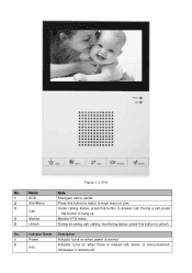
Monitor VTO video. Press this button to answer call. During a call , alarm, or announcement. Indicator Name Description 1 Power Indicator turns on when power is normal. 2 Info Indicator turns on when there is missed call , press this button to center. During incoming call to unlock. Name 1 SOS 2 Arm/Menu 3 Call 4 Monitor 5 Unlock Note Emergent call , calling, monitoring status, press this button to main menu or arm. Otherwise, it remains off. No. Under calling, status, press this button to return to hang up. Figure 1- 2 VTH No.
Monitor VTO video. Press this button to answer call. During a call , alarm, or announcement. Indicator Name Description 1 Power Indicator turns on when power is normal. 2 Info Indicator turns on when there is missed call , press this button to center. During incoming call to unlock. Name 1 SOS 2 Arm/Menu 3 Call 4 Monitor 5 Unlock Note Emergent call , calling, monitoring status, press this button to main menu or arm. Otherwise, it remains off. No. Under calling, status, press this button to return to hang up. Figure 1- 2 VTH No.
Product Manual
Page 7
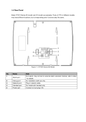
1.3 Rear Panel Make VTH15 Series AH model and CH model as examples. Name Note 1 8-ch alarm, may have different locations, but corresponding ports' functions stay the same. Ports of VTH of different models may connect to external alarm extension module, refer to label Alarm port for details. 2 Debug port For installation staff use only. 3 Network port Plug in network cable. 4 Handset port For model with handset only. 5 Power port Connect to 2-pin plug 12V. Figure 1- 3 VTH15 Series AH Model No.
1.3 Rear Panel Make VTH15 Series AH model and CH model as examples. Name Note 1 8-ch alarm, may have different locations, but corresponding ports' functions stay the same. Ports of VTH of different models may connect to external alarm extension module, refer to label Alarm port for details. 2 Debug port For installation staff use only. 3 Network port Plug in network cable. 4 Handset port For model with handset only. 5 Power port Connect to 2-pin plug 12V. Figure 1- 3 VTH15 Series AH Model No.
Product Manual
Page 8
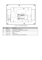
Name Description 1 Alarm Port 8-ch alarm, please refer to tag. 2 Debug Port Extension port, for RS485 communication port. 3 Network Port Plug in network cable. 4 Note: Alarm Output Reserved port. 5 Power Port Connect to 2-pin green 12V power supply. Figure 1- 4 VTH15 Series CH Model No.
Name Description 1 Alarm Port 8-ch alarm, please refer to tag. 2 Debug Port Extension port, for RS485 communication port. 3 Network Port Plug in network cable. 4 Note: Alarm Output Reserved port. 5 Power Port Connect to 2-pin green 12V power supply. Figure 1- 4 VTH15 Series CH Model No.
Product Manual
Page 9
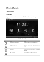
2 Product Function 2.1 Basic Function 2.1.1 Main Menu The product main interface has four menus: Video Talk, Security, Message, and Settings. It means device has SD card inserted. Icon Figure 2- 1 VTH15 series Name Network connection icon Note It means network connection is normal. It means device enable DND (do not disturb) function. VTO not connected DND icon SD card icon It means device does not connect to any VTO. See Figure 2- 1.
2 Product Function 2.1 Basic Function 2.1.1 Main Menu The product main interface has four menus: Video Talk, Security, Message, and Settings. It means device has SD card inserted. Icon Figure 2- 1 VTH15 series Name Network connection icon Note It means network connection is normal. It means device enable DND (do not disturb) function. VTO not connected DND icon SD card icon It means device does not connect to any VTO. See Figure 2- 1.
Product Manual
Page 10
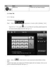
... no. Building 1, Unit 1, Room 101 is used for VTH to call (i.e. See Figure 2- 3. Figure 2- 2 Step 2. Note: If both the two indoor door stations are VTH-CM models (with front camera), then you can have a bidirectional talk. Click on contact book icon, user can call . See Figure 2- 2. When the user being called answers the call, user can perform a bidirectional visual...
... no. Building 1, Unit 1, Room 101 is used for VTH to call (i.e. See Figure 2- 3. Figure 2- 2 Step 2. Note: If both the two indoor door stations are VTH-CM models (with front camera), then you can have a bidirectional talk. Click on contact book icon, user can call . See Figure 2- 2. When the user being called answers the call, user can perform a bidirectional visual...
Product Manual
Page 12
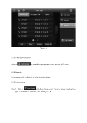
Figure 2- 4 2.1.2.4 Management Center Click on or press Emergency button, and it is to call MGT center. 2.1.3 Security In homepage, click on , interface shows current 8-ch area status, including Area Type, Current Status, and Delay Time. See Figure 2- 5. Click on Security to enter Security interface. 2.1.3.1 Armed zone Step 1.
Figure 2- 4 2.1.2.4 Management Center Click on or press Emergency button, and it is to call MGT center. 2.1.3 Security In homepage, click on , interface shows current 8-ch area status, including Area Type, Current Status, and Delay Time. See Figure 2- 5. Click on Security to enter Security interface. 2.1.3.1 Armed zone Step 1.
Product Manual
Page 13
Figure 2- 6 You can set bypass and delete for 4~8 channels to enter area setting interface. See Figure 2- 6. Click on Set, input password, to disable area for one time or long-term. Default password is user password. Note: The entry password is 123456, please see Ch 2.1.5. Figure 2- 5 Step 2.
Figure 2- 6 You can set bypass and delete for 4~8 channels to enter area setting interface. See Figure 2- 6. Click on Set, input password, to disable area for one time or long-term. Default password is user password. Note: The entry password is 123456, please see Ch 2.1.5. Figure 2- 5 Step 2.
Product Manual
Page 14
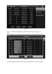
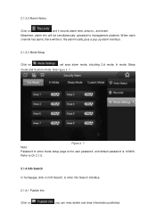
... to Ch 2.1.5. 2.1.4 Info Search In homepage, click on Info Search, to enter Info Search interface. 2.1.4.1 Publish Info Click on , set area alarm mode, including Out mode, In mode, Sleep mode and Custom mode. Meantime, alarm info will be simultaneously uploaded to enter mode setup page is the user password, and default password is 123456. 2.1.3.2 Alarm History Click on , and it records alarm time, area no., and event.
... to Ch 2.1.5. 2.1.4 Info Search In homepage, click on Info Search, to enter Info Search interface. 2.1.4.1 Publish Info Click on , set area alarm mode, including Out mode, In mode, Sleep mode and Custom mode. Meantime, alarm info will be simultaneously uploaded to enter mode setup page is the user password, and default password is 123456. 2.1.3.2 Alarm History Click on , and it records alarm time, area no., and event.
Product Manual
Page 16
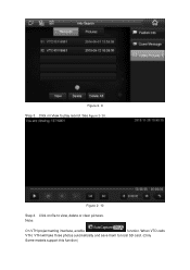
Figure 2- 10 Step 4. Click on View to play record. Note: On VTH project setting interface, enable function. See Figure 2- 10. When VTO calls VTH, VTH will take three photos automatically and save them to view, delete or clear pictures. Click on file to local SD card. (Only Some models support this function) Figure 2- 9 Step 3.
Figure 2- 10 Step 4. Click on View to play record. Note: On VTH project setting interface, enable function. See Figure 2- 10. When VTO calls VTH, VTH will take three photos automatically and save them to view, delete or clear pictures. Click on file to local SD card. (Only Some models support this function) Figure 2- 9 Step 3.
Product Manual
Page 17
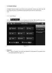
See Figure 2- 11. Click on , you can set password, ring, talk, DND, local IPC, clean, touch ring, SD card and snapshot plus restore default settings. You can set screen brightness, incoming ring, alarm ring, talk time, DND time and etc. The following introduces the most commonly used functions. Figure 2- 11 Password Step 1. See Figure 2- 12. 2.1.5 System Settings In System Settings interface, user can set user password, unlock password, arm password and anti-hijack password. User 2.1.5.1 User Settings Click on Password.
See Figure 2- 11. Click on , you can set password, ring, talk, DND, local IPC, clean, touch ring, SD card and snapshot plus restore default settings. You can set screen brightness, incoming ring, alarm ring, talk time, DND time and etc. The following introduces the most commonly used functions. Figure 2- 11 Password Step 1. See Figure 2- 12. 2.1.5 System Settings In System Settings interface, user can set user password, unlock password, arm password and anti-hijack password. User 2.1.5.1 User Settings Click on Password.
Product Manual
Page 18
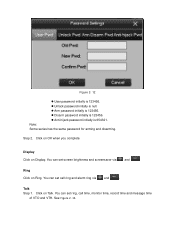
.... Arm password initially is 123456. Disarm password initially is 123456. Anti-hijack password initially is 654321. You can set call time, monitor time, record time and message time of VTO and VTH. Ring Click on Talk. Click on Ring. Note: Some series has the same password for arming and disarming. You can set ring, call ring and alarm ring via and . See Figure 2- 13. Display Click on...
.... Arm password initially is 123456. Disarm password initially is 123456. Anti-hijack password initially is 654321. You can set call time, monitor time, record time and message time of VTO and VTH. Ring Click on Talk. Click on Ring. Note: Some series has the same password for arming and disarming. You can set ring, call ring and alarm ring via and . See Figure 2- 13. Display Click on...
Product Manual
Page 20
... 2. Click on talk to enter SD card setting interface is the user password, which is on. Note: Password to view added IPC video. OFF means touch sound is off . Step 3. Clean Click on SD Card, you can view SD card free space or format SD card. Auto Capture (Snapshot) Slide . SD card Click on Clean to restore system default settings. In...
... 2. Click on talk to enter SD card setting interface is the user password, which is on. Note: Password to view added IPC video. OFF means touch sound is off . Step 3. Clean Click on SD Card, you can view SD card free space or format SD card. Auto Capture (Snapshot) Slide . SD card Click on Clean to restore system default settings. In...
Product Manual
Page 21
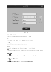
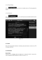
In pop-up box, input arm password (default password is for installer user only. 2.1.5.2 Project Settings Click on 002236. 2.1.5.2 Introduction , this product and problems might encounter Figure 2- 15 2.2 Unlock When VTH is Click on VTH to remotely unlock door. 2.3 Arm/Disarm Disarm Status Press arm icon in homepage, select one mode (out, in, sleep and custom). See Figure 2- 16. See Figure 2- 15. , you can view this function is 123456.). The entry password is being called, monitored, in call status, press unlock button or unlock icon on during usage.
In pop-up box, input arm password (default password is for installer user only. 2.1.5.2 Project Settings Click on 002236. 2.1.5.2 Introduction , this product and problems might encounter Figure 2- 15 2.2 Unlock When VTH is Click on VTH to remotely unlock door. 2.3 Arm/Disarm Disarm Status Press arm icon in homepage, select one mode (out, in, sleep and custom). See Figure 2- 16. See Figure 2- 15. , you can view this function is 123456.). The entry password is being called, monitored, in call status, press unlock button or unlock icon on during usage.
Product Manual
Page 23
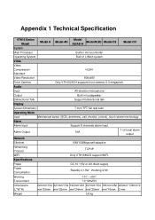
...800x480 Front Camera Only VTH1520CH supports front camera, 0.3 megapixel. Appendix 1 Technical Specification VTH15 Series Model Model Model A Model AH Model B(W) Model CS AS/AS-H Model CH System Main Processor Built-in microcontroller Operating System Built-in loudspeaker Bidirectional Talk Support bidirectional talk Display Screen Dimension 7 inch TFT full real color Operating Mode Input Mechanical button (SOS, arm/menu, call, monitor, unlock), touch screen technology Alarm Alarm Input Support 8 channels alarm input Alarm Output 1-ch local alarm N/A output Network...
...800x480 Front Camera Only VTH1520CH supports front camera, 0.3 megapixel. Appendix 1 Technical Specification VTH15 Series Model Model Model A Model AH Model B(W) Model CS AS/AS-H Model CH System Main Processor Built-in microcontroller Operating System Built-in loudspeaker Bidirectional Talk Support bidirectional talk Display Screen Dimension 7 inch TFT full real color Operating Mode Input Mechanical button (SOS, arm/menu, call, monitor, unlock), touch screen technology Alarm Alarm Input Support 8 channels alarm input Alarm Output 1-ch local alarm N/A output Network...
Product Manual
Page 24
Note: This manual is any uncertainty or controversy, please refer to change without prior written notice. All trademarks and registered trademarks are subject to the final explanation of their respective owners. If there is for more information. Slight difference may be found in user interface. All the designs and software here are the properties of us. Please visit our website or contact userr local service engineer for reference only.
Note: This manual is any uncertainty or controversy, please refer to change without prior written notice. All trademarks and registered trademarks are subject to the final explanation of their respective owners. If there is for more information. Slight difference may be found in user interface. All the designs and software here are the properties of us. Please visit our website or contact userr local service engineer for reference only.
